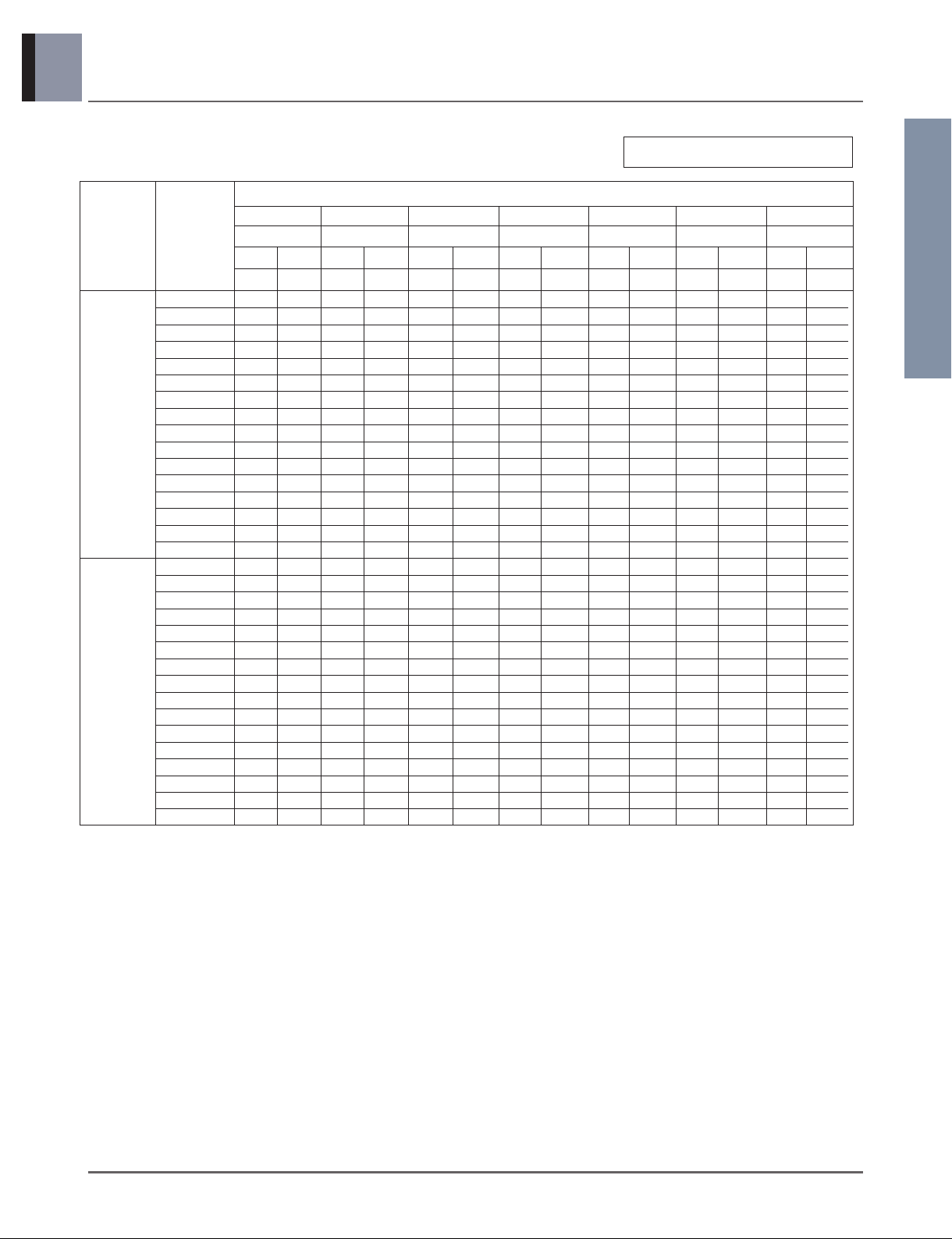
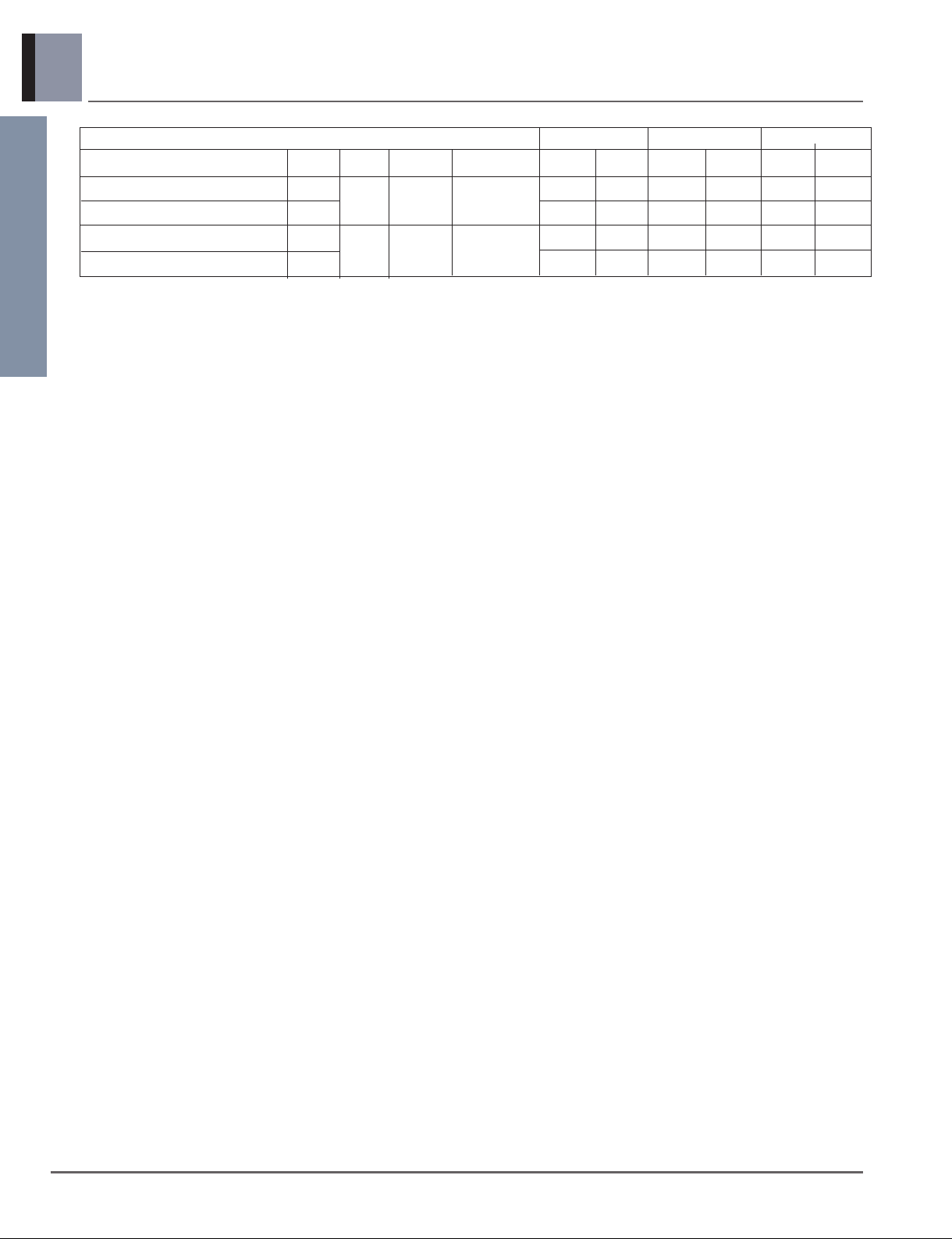
LG ARNU18GS5 2 Series, ARNU24GS5 2 Series User manual

LCS
(Light Commercial System)
Indoor unit
LCS
(Light Commercial System)
Indoor unit
Wall Mounted
1. List of functions
2. Specifications
3. Dimensions
4. Piping Diagrams
5. Wiring Diagrams
6. Capacity Tables
7. Air Velocity and Temperature Distribution
8. Electric Characteristics
9. Sound Levels
10. Installation
11. Accessories

Indoor Units
1_ Wall Mounted
LCS
(Light Commercial System)
Indoor unit
1. List of functions
Air supply outlet
Airflow direction control(left & right)
Airflow direction control(up & down)
Auto swing(left & right)
Air flow Auto swing(up & down)
Airflow steps(fan/cool/heat)
Chaos swing
Chaos wind(auto wind)
Jet cool(Power wind)
Swirl wind
Deodorizing filter
Air purifying Plasma air purifier
Prefilter(washable / anti-fungus)
Drain pump
Installation E.S.P. control
Electric heater(operation)
High ceiling operation
Hot start
Reliability Self diagnosis
Soft dry operation
Auto changeover
Auto cleaning
Auto operation(artificial intelligence)
Auto restart operation
Child lock
Convenience Forced operation
Group control
Sleep mode
Timer(on/off)
Timer(weekly)
Two thermistor control
Wide wired remote controller
Deluxe wired remote controller
Individual Simple wired remote controller
control Wired remote controller(for hotel use)
Wireless remote controller(simple)
Wireless LCD remote control
Special Zone control
function kit CTIE
Electro thermostat
1
Auto
Auto
Auto
X
3 / 4 / 3
O
O
O
-
X
Option
O
-
-
-
-
O
O
O
O(Heat recovery)
O
O(Heat pump or Cooling only)
O
O
O
O
O
O
O
O
Accessory
Accessory
Accessory
Accessory
Accessory
Accessory
-
-
-
FunctionCategory
ARNU18GS5*2, ARNU24GS5*2
O : Applied X : Not applied – : No relation
Option : Model name & price are different according to options, and assembled in factory with main unit.
Accessory : Installed at field, ordered and purchased separately by the corresponding model name, supplied with separate
package.

Wall Mounted _ 2
Indoor Units
LCS
(Light Commercial System)
Indoor unit
2. Specifications
Notes:-
1. Capacities are based on the following conditions:
Cooling • Indoor temp. 27°C[80.6°F]DB/ 19°C[66.2°F]WB
• Outdoor temp. 35°C[95°F]DB/ 24°C[75.2°F]WB
• Interconnecting Piping Length 7.5m
• Level Difference of Zero
Heating • Indoor temp. 20°C[68°F]DB/ 15°C[59°F]WB
• Outdoor temp. 7°C[44.6°F]DB/ 6°C[42.8°F]WB
• Interconnecting Piping Length 7.5m
• Level Difference of Zero
2. Capacities are net capacities
3. Due to our policy of innovation some specifications may be changed without prior notification
4. To be added for more available Models
5. EEV : Electronic Expansion Valve
6. Anechoic chamber conversion value is measured at 1 m downward from unit centre.
The values depends on the ambient conditions and values are normally higher in actual operation.
Type
Model Unit
kW
Cooling Capacity kcal/h
Btu/h
kW
Heating Capacity kcal/h
Btu/h
Dimensions(WxDxH)
Body mm
inch
Coil
Rows x Columns x FPI
Face Area m3
Type
Motor Output x Number
W
Running Current A
Fan
Air Flow Rate(H / M / L)
CMM
cfm
Drive
Motor type
Temperature Control
Sound Absorbing Thermal Insulation Material
Air Filter
Safety Device
Liquid Side mm(inch)
Pipe Connections
Gas Side mm(inch)
Drain Pipe(Internal Dia.)
mm(inch)
Net Weight kg(lbs)
Noise Level
(Sound Press, 1m, H / M / L)
dB(A)
Power Supply Ø, V, Hz
Refrigerant Control
Power cable mm2
Transmission cable mm2
Color
Wall Mounted
ARNU18GS5*2 ARNU24GS5*2
5.6 7.1
4,800 6,100
19,100 24,200
6.3 8.0
5,400 6,900
21,500 27,300
1,090 x 178 x 300 1,090 x 178 x 300
42.9 x 7 x 11.8 42.9 x 7 x 11.8
2 x 15 x 20 2 x 15 x 20
0.26 0.26
Cross Flow Fan Cross Flow Fan
20 20
0.2 0.2
12.0 / 10.5 / 9.0 14.0 / 13.0 / 10.0
424.0 / 371.0 / 318.0 494.0 / 459.0 / 353.0
Direct Direct
BLDC BLDC
Microprocessor, Thermostat for cooling and heating Microprocessor, Thermostat for cooling and heating
Foamed polystrene Foamed polystrene
Resin Net(washable) Resin Net(washable)
Fuse Fuse
Ø6.35(1/4) Ø9.52(3/8)
Ø12.7(1/2) Ø15.88(5/8)
16(5/8) 16(5/8)
12(26.5) 12(26.5)
44 / 40 / 36 46 / 41 / 38
1, 220-240, 50 1, 220-240, 50
1, 220, 60 1, 220, 60
EEV EEV
CV1.5 x 3C CV1.5 x 3C
CVV-SB 1.0~1.5 x 2C CVV-SB 1.0~1.5 x 2C
Morning fog Morning fog
* Model Name
A:Basic L:Plasma
Conversion Formula
kcal/h= kW x 860
Btu/h = kW x 3412
cfm = m3/min x 35.3
l/s = CMM x 1000/60

Indoor Units
3_ Wall Mounted
LCS
(Light Commercial System)
Indoor unit
3. Dimensions
76, Seongsan-dong, Changwon City, Gyeongnam,
641-713, Korea CHASSIS CODE: S5
Wall Mounted
ARNU18GS5*2
ARNU24GS5*2
WModel
ARNU18GS5*2
ARNU24GS5*2
HD
1090 300 178
Note
1. Unit should be installed in compliance with the installation manual
in the product box.
2. Unit shall be grounded in accordance with the local regulations or
applicable national codes.
(unit : mm)
1,090
178
300
281
804
Name
1
Air discharge grill
2
Air suction grill
Number Descripition
(unit : mm)
1
2

Wall Mounted _ 4
Indoor Units
LCS
(Light Commercial System)
Indoor unit
4. Piping Diagrams
Heat Exchanger
C.F.F
lndoor unit
EEV :Heating
:Cooling
Filter
Filter
Th3 Th2
Th1
Refrigerant pipe connection port diameter
MODEL GAS LIQUID
ARNU18GS5*2 Ø12.7(1/2) Ø6.35(1/4)
ARNU24GS5*2 Ø15.88(5/8) Ø9.52(3/8)
[Unit: mm(inch)]
LOC. Description
Th1 Room thermistor
Th2 Pipe in thermistor
Th3 Pipe out thermistor

Indoor Units
5_ Wall Mounted
LCS
(Light Commercial System)
Indoor unit
5. Wiring Diagrams
CONNECTOR NUMBER
LOCATION POINT FUNCTION
CN-POWER AC Power supply AC Power line input for indoor controller
CN-MOTOR1 Fan motor output Motor output of BLDC
CN-COM Communication Connection between indoor and outdoor
CN-DISP1 Display Display of indoor status
CN-DISP2 Display Display of indoor status
CN-EEV EEV output EEV control output
CN-U/D, CN-L/R Step motor Step motor output
CN-TH1 Room/pipe sensor Room and pipe thermistor
CN-REMO Remote controller Remote control line
CN-CC Dry contact Dry contact line
CN-HVB Air clean Air clean control
S5 Chassis

Wall Mounted _ 6
Indoor Units
LCS
(Light Commercial System)
Indoor unit
6. Capacity Tables
Capacity
Index
Outdoor
air temp.
(DB, °C)
Indoor air temp. (DB/WB, °C)
20 23 26 27 28 30 32
14 16 18 19 20 22 24
TC SHC TC SHC TC SHC TC SHC TC SHC TC SHC TC SHC
kW kW kW kW kW kW kW kW kW kW kW kW kW kW
7.1
10 3.8 3.3 4.5 3.7 5.2 4.0 5.6 4.0 6.0 4.2 6.7 4.3 7.4 4.3
12 3.8 3.3 4.5 3.7 5.2 4.0 5.6 4.0 6.0 4.2 6.7 4.3 7.3 4.2
14 3.8 3.3 4.5 3.7 5.2 4.0 5.6 4.0 6.0 4.2 6.7 4.3 7.2 4.2
16 3.8 3.3 4.5 3.7 5.2 4.0 5.6 4.0 6.0 4.2 6.7 4.3 7.1 4.1
18 3.8 3.3 4.5 3.7 5.2 4.0 5.6 4.0 6.0 4.2 6.7 4.3 7.0 4.1
20 3.8 3.3 4.5 3.7 5.2 4.0 5.6 4.0 6.0 4.2 6.7 4.3 6.9 4.0
21 3.8 3.3 4.5 3.7 5.2 4.0 5.6 4.0 6.0 4.2 6.7 4.3 6.8 4.0
23 3.8 3.3 4.5 3.7 5.2 4.0 5.6 4.0 6.0 4.2 6.7 4.3 6.7 3.9
25 3.8 3.3 4.5 3.7 5.2 4.0 5.6 4.0 6.0 4.2 6.6 4.3 6.6 3.9
27 3.8 3.3 4.5 3.7 5.2 4.0 5.6 4.0 6.0 4.2 6.4 4.2 6.6 3.8
29 3.8 3.3 4.5 3.7 5.2 4.0 5.6 4.0 6.0 4.2 6.4 4.1 6.5 3.8
31 3.8 3.3 4.5 3.7 5.2 4.0 5.6 4.0 6.0 4.2 6.3 4.1 6.4 3.7
33 3.8 3.3 4.5 3.7 5.2 4.0 5.6 4.0 6.0 4.2 6.2 4.0 6.3 3.7
35 3.8 3.3 4.5 3.7 5.2 4.0 5.6 4.0 6.0 4.2 6.0 3.9 6.2 3.6
37 3.8 3.3 4.5 3.7 5.2 4.0 5.6 4.0 5.8 4.1 5.9 3.8 6.1 3.6
39 3.8 3.3 4.5 3.7 5.2 4.0 5.6 4.0 5.7 4.0 5.8 3.8 6.0 3.5
10 4.8 4.2 5.7 4.6 6.6 5.0 7.1 5.1 7.6 5.3 8.5 5.5 9.3 5.4
12 4.8 4.2 5.7 4.6 6.6 5.0 7.1 5.1 7.6 5.3 8.5 5.5 9.2 5.4
14 4.8 4.2 5.7 4.6 6.6 5.0 7.1 5.1 7.6 5.3 8.5 5.5 9.1 5.3
16 4.8 4.2 5.7 4.6 6.6 5.0 7.1 5.1 7.6 5.3 8.5 5.5 9.0 5.2
18 4.8 4.2 5.7 4.6 6.6 5.0 7.1 5.1 7.6 5.3 8.5 5.5 8.8 5.2
20 4.8 4.2 5.7 4.6 6.6 5.0 7.1 5.1 7.6 5.3 8.5 5.5 8.7 5.1
21 4.8 4.2 5.7 4.6 6.6 5.0 7.1 5.1 7.6 5.3 8.5 5.5 8.7 5.1
23 4.8 4.2 5.7 4.6 6.6 5.0 7.1 5.1 7.6 5.3 8.5 5.5 8.5 5.0
25 4.8 4.2 5.7 4.6 6.6 5.0 7.1 5.1 7.6 5.3 8.4 5.4 8.4 4.9
27 4.8 4.2 5.7 4.6 6.6 5.0 7.1 5.1 7.6 5.3 8.2 5.3 8.3 4.9
29 4.8 4.2 5.7 4.6 6.6 5.0 7.1 5.1 7.6 5.3 8.1 5.2 8.2 4.8
31 4.8 4.2 5.7 4.6 6.6 5.0 7.1 5.1 7.6 5.3 8.0 5.1 8.1 4.7
33 4.8 4.2 5.7 4.6 6.6 5.0 7.1 5.1 7.6 5.3 7.8 5.1 7.9 4.6
35 4.8 4.2 5.7 4.6 6.6 5.0 7.1 5.1 7.6 5.3 7.7 5.0 7.8 4.6
37 4.8 4.2 5.7 4.6 6.6 5.0 7.1 5.1 7.4 5.1 7.5 4.9 7.7 4.5
39 4.8 4.2 5.7 4.6 6.6 5.0 7.1 5.1 7.2 5.0 7.4 4.8 7.6 4.4
5.6
Notes:
TC: Total Capacity(kW) SHC: Sensible Heat Capacity(kW)
6.1 Cooling Capacity Cooling Capacity

Indoor Units
7_ Wall Mounted
LCS
(Light Commercial System)
Indoor unit
6. Capacity Tables
6.2 Heating Capacity Heating Capacity
Notes: TC: Total Capacity(kW)
Capacity
Index
Outdoor air
temp.
DB(°C) WB(°C)
Indoor air temp. (DB, °C)
16 18 20 21 22 24
TC TC TC TC TC TC
kW kW kW kW kW kW
-19.8 -20.0 4.2 4.2 4.2 4.2 4.2 4.2
-18.8 -19.0 4.3 4.3 4.3 4.3 4.3 4.3
-16.7 -17.0 4.6 4.6 4.6 4.6 4.6 4.5
-14.7 -15.0 4.9 4.8 4.3 4.8 4.8 4.8
-12.6 -13.0 5.1 5.1 4.5 5.0 5.0 5.0
-10.5 -11.0 5.4 5.4 4.8 5.4 5.3 5.3
-9.5 -10.0 5.4 5.4 4.9 5.4 5.4 5.4
-8.5 -9.1 5.5 5.5 5.0 5.5 5.5 5.4
-7.0 -7.6 5.7 5.7 5.1 5.6 5.6 5.5
-5.0 -5.6 6.0 6.0 5.4 5.8 5.8 5.5
-3.0 -3.7 6.2 6.2 5.5 6.1 5.9 5.5
0.0 -0.7 6.6 6.6 5.8 6.1 5.9 5.5
3.0 2.2 7.0 6.7 6.2 6.1 5.9 5.5
5.0 4.1 7.1 6.7 6.3 6.1 5.9 5.5
7.0 6.0 7.2 6.7 6.3 6.1 5.9 5.5
9.0 7.9 7.2 6.7 6.3 6.1 5.9 5.5
11.0 9.8 7.2 6.7 6.3 6.1 5.9 5.5
13.0 11.8 7.2 6.7 6.3 6.1 5.9 5.5
15.0 13.7 7.2 6.7 6.3 6.1 5.9 5.5
-19.8 -20.0 5.4 5.4 5.4 5.3 5.3 5.3
-18.8 -19.0 5.5 5.5 5.5 5.5 5.4 5.4
-16.7 -17.0 5.8 5.8 5.8 5.8 5.8 5.8
-14.7 -15.0 6.2 6.1 5.5 6.1 6.1 6.1
-12.6 -13.0 6.5 6.5 5.8 6.4 6.4 6.4
-10.5 -11.0 6.8 6.8 6.0 6.8 6.7 6.7
-9.5 -10.0 6.9 6.9 6.2 6.9 6.9 6.8
-8.5 -9.1 7.0 7.0 6.3 7.0 7.0 6.8
-7.0 -7.6 7.3 7.3 6.5 7.1 7.1 7.0
-5.0 -5.6 7.6 7.6 6.8 7.4 7.4 7.0
-3.0 -3.7 7.9 7.9 7.0 7.7 7.5 7.0
0.0 -0.7 8.4 8.4 7.4 7.8 7.5 7.0
3.0 2.2 8.9 8.6 7.8 7.8 7.5 7.0
5.0 4.1 9.0 8.6 8.0 7.8 7.5 7.0
7.0 6.0 9.2 8.6 8.0 7.8 7.5 7.0
9.0 7.9 9.2 8.6 8.0 7.8 7.5 7.0
11.0 9.8 9.2 8.6 8.0 7.8 7.5 7.0
13.0 11.8 9.2 8.6 8.0 7.8 7.5 7.0
15.0 13.7 9.2 8.6 8.0 7.8 7.5 7.0
5.6
7.1

Wall Mounted _ 8
Indoor Units
LCS
(Light Commercial System)
Indoor unit
7. Air Velocity and Temperature Distribution(Reference Data)
ARNU18GS5*2
18
20
22
24
1.00.5
2.5
1.5
Air velocity [m/s]
Temperature [°C]
2.7m
2m
1m
0m
8m 7m 6m 5m 4m 3m 2m 1m 0m
2.7m
2m
1m
0m
8m 7m 6m 5m 4m 3m 2m 1m 0m
1.0 2.0
1.5
0.5
Air velocity [m/s]
Temperature [°C]
2.7m
2m
1m
0m
8m 7m 6m 5m 4m 3m 2m 1m 0m
2.7m
2m
1m
0m
8m 7m 6m 5m 4m 3m 2m 1m 0m
33
30
27
24
21
Cooling
Discharge angle:45°
Heating
Discharge angle:50°

Indoor Units
9_ Wall Mounted
LCS
(Light Commercial System)
Indoor unit
8. Electric Characteristics
Symbols:
MCA :Min, Circuit Amps(A)
MFA:Max. Fuse Amps(see note 5)
kW:Fan Motor Rated Output(kW)
FLA:Full Load Amps(A)
IFM:Indoor Fan Motor
Note :
1. Voltage range
Units are suitable for use on electrical systems where voltage supplied to unit terminals is not below or above
the listed range limits.
2. Maximum allowable voltage unbalance between phases is 2%
3. MCA/MFA
MCA=1.25 x FLA
MFA≤ 4 x FLA
(Next lower standard fuse rating. Min. 15A)
4. Select wire size based on the MCA
5. Instead of fuse, use Circuit Breaker.
Units
Model Type Hz Volts
Voltage Range
ARNU18GS5*2 S5 50 220 - 240 Max:264 0.29 15 0.02 0.23 40 40
ARNU24GS5*2 S5 Min:198 0.29 15 0.02 0.23 40 40
ARNU18GS5*2 S5 60 220 Max:242 0.29 15 0.02 0.23 40 40
ARNU24GS5*2 S5 Min:198 0.29 15 0.02 0.23 40 40
Power Supply IFM Input(W)
MCA MFA kW FLA Cooling Heating

Wall Mounted _ 10
Indoor Units
LCS
(Light Commercial System)
Indoor unit
9. Sound Levels
Overall
Sound Pressure Level
Model
ARNU18GS5*2
ARNU24GS5*2
Sound Levels dB(A)
H M L
44
46 40
41 36
38
1m
1m
Microphone
Notes:
- Data is valid at nominal operating condition
- Reference accoustic pressure OdB = 20µPa
- Sound level will vary depending on a range of factors such as
the construction(acoustic absorption coefficient) of particular
room in which the equipment is installed.
ARNU18GS5*2 ARNU24GS5*2
Octave Band Sound Pressure Level (dB re 20µPa )
10
20
30
40
50
60
70
80
63 125 250 500 1000 2000 4000 8000
Octave Band Center Frequency (Hz)
NC-15
NC-20
NC-25
NC-30
NC-35
NC-40
NC-45
NC-50
NC-55
NC-60
NC-65
Approximate
Hearing
Threshold
10
20
30
40
50
60
70
80
63 125 250 500 1000 2000 4000 8000
Octave Band Center Frequency (Hz)
NC-15
NC-20
NC-25
NC-30
NC-35
NC-40
NC-45
NC-50
NC-55
NC-60
NC-65
Approximate
Hearing
Threshold

Indoor Units
11 _ Wall Mounted
LCS
(Light Commercial System)
Indoor unit
10. Installation
• Please read the instruction sheetss completely before installing the product.
• When the power cord is damaged, replacement work shall be performed by authorized personnel only.
• Installation work must be performed in accordance with the national wiring standards by authorized personnel only.
Installation Parts Provided
1. Type "A" screw
2. Installation Plate
Required Parts Required Tools
❏ Installation plate
❏Four type "A" screws
❏Connecting cable
❏Level gauge
❏Screw driver
❏Electric drill
❏Hole core drill
❏Pipes: Gas side
Liquid side
❏Insulation materials
❏Additional drain pipe ❏Flaring tool set
❏Specified torque wrenches
❏Spanner......................................................Half union
❏A glass of water
❏Screw driver
❏Thermometer

Wall Mounted _ 12
Indoor Units
LCS
(Light Commercial System)
Indoor unit
10. Installation
10.1 Selection of the best location
• There should not be any heat source or
steam near the unit.
• There should not be any obstacles to prevent air cir-
culation.
• A place where air circulation in the room will be
good.
• A place where drainage can be easily obtained.
• A place where noise prevention is taken into consid-
eration.
• Do not install the unit near the door way.
• Ensure the spaces indicated by arrows from the wall,
ceiling, fence, or other obstacles.
The mounting wall should be strong and solid enough to
protect it from vibration.
1.Mount the installation plate on the wall with
four Type "A" screws.
(If mounting the unit on the concrete wall, consider using
anchor bolts.)
• Always mount the Installation plate horizontally by
aligning the marking-off line by means of thread and a
level.
Front
Right Rear right
Rear left
Down right
Left
More than 200mm
More than
100mm
More than 2300mm
More than
100mm
S5 chassis
Installation Plate
Chassis
Hook
Type “A”

Indoor Units
13 _ Wall Mounted
LCS
(Light Commercial System)
Indoor unit
10. Installation
Preparing work for installation
■Preparing the indoor unit's piping and drain hose for
installation through the wall.
■Remove the plastic tubing retainer(see illustration
below) and pull the tubing and drain hose away from
chassis.
■Replace the plastic tubing holder in the original position.
1. Route the indoor tubing and the drain hose in
the direction of rear left.
2. Insert the connecting cable into the indoor
unit from the outdoor unit through the piping
hole.
■Do not connect the cable to the indoor unit.
■Make a small loop with the cable for easy connection
later.
3. Tape the tubing, drain hose and the connect-
ing cable. Be sure that the drain hose is locat-
ed at the lowest side of the bundle. Locating
at the upper side can cause drain pan to over-
flow inside the unit.
NOTE: If the drain hose is routed inside the room, insulate
the hose with an insulation material* so that dripping from
"sweating"(condensation) will not damage furniture or
floors.
*Foamed polyethylene or equivalent is recommended.
4. Indoor unit installation
■Hook the indoor unit onto the upper portion of the
installation plate.(Engage the two hooks of the rear
top of the indoor unit with the upper edge of the
installation plate.) Ensure that the hooks are properly
seated on the installation plate by moving it left and
right.
Press the lower left and right sides of the unit against
the installation plate until the hooks engage into their
slots(clicking sound).
5. Connecting the pipings to the indoor unit and
drain hose to drain pipe.
■Align the center of the pipings and sufficiently tighten
the flare nut by hand.
For left rear piping
While installing, make sure that the
remaining parts must be removed
clearly so as not to damage the piping
and drain hose, especially power cord
and connecting cable.
To remove the holder,
press the bottom of
chassis near the holder
upward and pull the tab
out of its hole.
Tubing holder
Pull
Press 2
1
Drain hose
Connecting
cable
Loop
Gas side
piping
Liquid side
piping
Drain hose
Drain hose
Connecting
cable
Indoor unit tubing Flare nut Pipings
CAUTION

Wall Mounted _ 14
Indoor Units
LCS
(Light Commercial System)
Indoor unit
10. Installation
■Tighten the flare nut with a wrench.
■When extending the drain hose at the indoor unit,
install the drain pipe.
6. Wrap the insulation material around the con-
necting portion.
■Overlap the connection pipe insulation material
and the indoor unit pipe insulation material. Bind
them together with vinyl tape so that there is no
gap.
■Wrap the area which accommodates the rear pip-
ing housing section with vinyl tape.
■Bundle the piping and drain hose together by
wrapping them with vinyl tape over the range with-
in which they fit into the rear piping housing sec-
tion.
1. Route the indoor tubing and the drain hose to
the required piping hole position.
2. Insert the piping, drain hose and the connect-
ing cable into the piping hole.
For right rear piping
Torque
wrench
Indoor
unit tubing
Spanner (fixed)
Connection
pipe
Flare nut
Vinyl tape(narrow)
Connection
pipe
Connecting cable
Vinyl tape
(wide) Wrap with vinyl tape
Indoor
unit pipe
Pipe
Wrap with vinyl tape
Drain hose
Pipe
Vinyl tape(wide)
Drain pipe
Connecting
cable
Vinyl tape(narrow)
Adhesive
Drain pipe
Indoor unit
drain hose
Plastic bands Insulation material

Indoor Units
15 _ Wall Mounted
LCS
(Light Commercial System)
Indoor unit
10. Installation
3. Insert the connecting cable into the indoor unit.
■Don't connect the cable to the indoor unit.
■Make a small loop with the cable for easy connec-
tion later.
4. Tape the drain hose and the connecting cable.
• Connecting cable
5. Indoor unit installation
■Hang the indoor unit from the hooks at the top of
the installation plate.
■Insert the spacer etc. between the indoor unit and
the installation plate and separate the bottom of the
indoor unit from the wall.
6. Connecting the pipings to the indoor unit and
the drain hose to drain pipe.
■Align the center of the pipings and sufficiently tight-
en the flare nut by hand.
■Tighten the flare nut with a wrench.
■When extending the drain hose at the indoor unit,
install the drain pipe.
7. Wrap the insulation material around the con-
necting portion.
■Overlap the connecting pipe heat insulation and the
indoor unit pipe heat insulation material. Bind them
together with vinyl tape so that there is no gap.
■Wrap the area which accommodates the rear piping
housing section with vinyl tape.
Vinyl tape
Adhesive
Drain hose
Indoor unit drain hose
(narrow)
Plastic bands Insulation material
Vinyl tape
(narrow)
Connection
pipe
Connecting
cable
Indoor
unit piping
Pipe
Vinyl tape
(wide)
Wrap with vinyl tape
Installation plate
Spacer
Indoor unit
80mm
(2-3/16 inch)
Indoor unit tubing Flare nut Pipings
Torque
wrench
Indoor
unit tubing
Spanner (fixed)
Connection
pipe
Flare nut

Wall Mounted _ 16
Indoor Units
LCS
(Light Commercial System)
Indoor unit
10. Installation
■Bundle the piping and drain hose together by wrap-
ping them with cloth tape over the range within
which they fit into the rear piping housing section.
8. Reroute the pipings and the drain hose across
the back of the chassis.
9. Set the pipings and the drain hose to the back
of the chassis with the tubing holder.
■Hook the edge of tubing holder to tap on chassis
and push the bottom of tubing holder to be
engaged at the bottom of chassis.
10. Indoor unit installation
■Remove the spacer.
■Ensure that the hooks are properly seated on the
installation plate by moving it left and right.
Press the lower left and right sides of the unit against
the installation plate until the hooks engage into their
slots(clicking sound).
Drain hose Vinyl tape
(narrow)
Pipe
Wrap with
vinyl tape(wide)
Drain hose
Connecting
Piping for
passage through
piping hole
Tubing holder
Hook
Push
2
1

Indoor Units
17 _ Wall Mounted
LCS
(Light Commercial System)
Indoor unit
10. Installation
10.2 Connection of Pipings
1. To remove the front panel from the indoor unit,
remove the front panel from the indoor unit
cabinet.
■Set the air direction louvers up-and-down to the
position(horizontally) by hand.
■Remove the securing screws that retain the front
panel. Pull the lower left and right sides of the grille
toward you and lift it off.
(2.1/7, 2.6/9, 3.5/12 kW/Btu models: 2EA,
3.5/18 kW/Btu models: 3EA)
2. To check the drainage.
■Pour a glass of water on the evaporator.
■Ensure the water flows through the drain hose of the
indoor unit without any leakage and goes out the
drain exit.
Pull the right and
the left side.
Screw
10.3 Connect the cable to the
indoor unit
1. Connect the wires to the terminals on the
control board individually according to the
outdoor unit connection.
• Ensure that the color of the wires of outdoor
unit and the terminal No. are the same as those
of indoor unit respectively.
Connecting cable
Remote c
oRemote control cord
Remote control cord

Wall Mounted _ 18
Indoor Units
LCS
(Light Commercial System)
Indoor unit
10. Installation
2. Attach the Grille onto the cabinet.
• Grasp lower the left and right side of the Grille
and engage four tabs on the top inside edge of
the chassis.
• Press the Grille toward the chassis until it is
back in place.
Terminal Block Indoor
1(L) 2(N) 3 4
INDOOR POWER INPUT
A-- ----BAB
GND 12V
DRY2DRY1
INTERNETIDUSODU Outdoor
Unit
After the confirmation of the above conditions, prepare the wiring as follows:
1) As for the method of wiring, follow the circuit diagram posted on the inside of
control cover.
2) The screw which fasten the wiring in the casing of electrical fittings are liable to
come loose from vibrations to which the unit is subjected during the course of
transportation. Check them and make sure that they are all tightly fastened. (If
they are loose, it could cause burn-out of the wires.)
3) Confirm the specification of power source.
4) Confirm that electrical capacity is sufficient.
5) See to that the starting voltage is maintained at more than 90 percent of the
rated voltage marked on the name plate.
6) Confirm that the cable thickness is as specified in the power source specifica-
tion.
(Particularly note the relation between the cable length and thickness.)
7) In a wet or moist area, always install an earth leakage circuit breaker.
8) The following would be caused by voltage drop.
• Vibration of a magnetic switch, which will damage the contact point, fuse breaking,
disturbance of the normal function of the overload.
9) The means for disconnection from a power supply shall be incorporated in the
fixed wiring and have an air gap contact separation of at least 3mm in each
active(phase) conductor.
CAUTION

Indoor Units
19 _ Wall Mounted
LCS
(Light Commercial System)
Indoor unit
10. Installation
WIRED REMOTE CONTROLLER INSTALLATION
• Since the room temperature sensor is in the remote controller, the remote controller box should be installed in a place away
from direct sunlight, high humidity and direct supply of cold air to maintain proper space temperature.
Install the remote controller about 5ft(1.5m) above the floor in an area with good air circulation at an average temperature.
Do not install the remote controller where it can be affected by:
- Drafts, or dead spots behind doors and in corners.
- Hot or cold air from ducts.
- Radiant heat from sun or appliances.
- Concealed pipes and chimneys.
- Uncontrolled areas such as an outside wall behind the remote controller.
- This remote controller is equipped with a seven segment LED. display. For proper display of the remote controller
LED's, the remote controller should be installed properly as shown in Fig.1.
(The standard height is 1.2~1.5 m from floor level.)
Fig.1 Typical locations for remote controller
5feet
(1.5meters)
no
no
no
yes
RemoteController
TEMP
RemoteController
TEMP
RemoteController
TEMP
Table of contents
Other LG Air Conditioner manuals

LG
LG AS-W2463RH2 User manual

LG
LG LP0711WNR User manual

LG
LG LT1033HNR User manual

LG
LG Multi V ARNU243TSA4 User manual

LG
LG Multi V User manual

LG
LG MULTI-V CRNN-TE Series User manual

LG
LG LS-C0924DA0 User manual

LG
LG LPUC306KA0 User manual

LG
LG ARNU183S5L2 User manual

LG
LG LS243HLV3 Installation and operation manual

LG
LG Multi Type Air Conditioner User manual

LG
LG ABNQ18GHLA0 User manual

LG
LG LS-135GB User manual

LG
LG ARND DCR4 Series User manual

LG
LG AMNQ18GSKAA User manual

LG
LG LB-H1860HL User manual

LG
LG PP485B00K User manual

LG
LG Multi V User manual

LG
LG Wall-Mounted Air Conditioner User manual

LG
LG LS243HLV3 User manual