Due to our policy of continuous product innovation, some specications may change without notication.
©LG Electronics U.S.A., Inc., Englewood Cliffs, NJ. All rights reserved. “LG” is a registered trademark of LG Corp.
5
Airow restriction devices such as lters shall not exceed the
rated maximum static pressure limits of the indoor unit fan
assembly.
Doing so will cause product malfunction.
Do not install this product outdoors or where it will be
directly exposed to coastal conditions.
Air from the ocean may cause the evaporator ns to corrode, which could
cause product malfunction, improper operation, and shorten the expected
useful life of the product.
Do not install this product in a location that is noise
sensitive. Provide additional acoustical treatment as needed.
The risk is occupants may be discomforted.
When installing refrigerant piping, consider pipe expansion
and use are connections when connecting.
Improper pipe installation may lead to pipe fatigue, failure, and a rapid
release of refrigerant, frostbite, suffocation, physical injury, and or death.
Verify the piping system has been properly evacuated
(<500 ppm), and the system’s refrigerant charge is correct
before commissioning and after any repair is made.
Improper system evacuation and/or an improper refrigerant charge may
cause product malfunction.
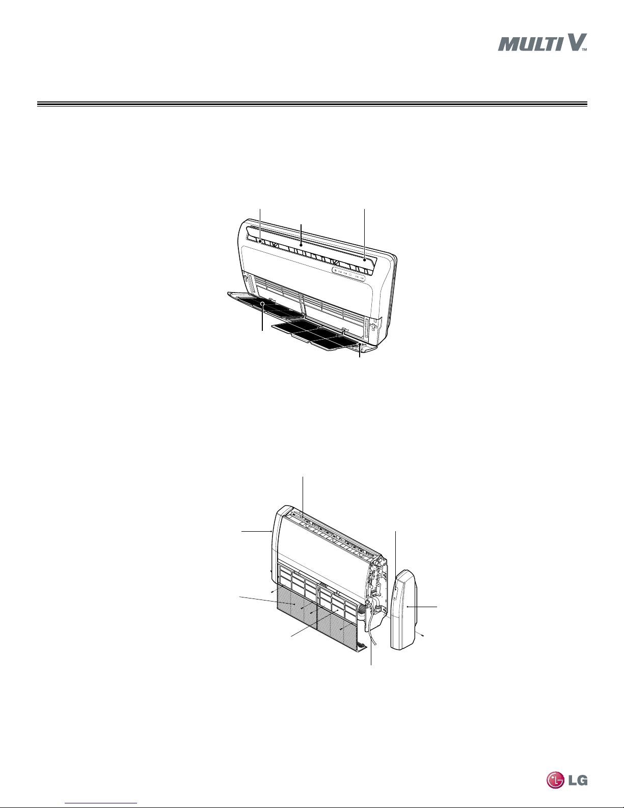
ROUGH-IN, CONTINUED
SAFETY PRECAUTIONS
POWER WIRING
The information contained in this manual is intended for use
by a qualied, experienced service technician who is familiar
with safety procedures and equipped with the proper tools
and test instruments.
Failure to carefully read and follow all instructions in this manual
can result in equipment malfunction, property damage, personal injury or
death.
This equipment uses high voltage electricity. Only a qualied,
experienced electrician should wire this system. Never
assume that the electrical power has been disconnected.
Verify with a meter.
Failure to properly respect electricity, use industry best grounding prac-
tices, follow suggested wiring instructions, local, and NEC codes can lead
to electrical shock, physical injury, seizures, and death.
Use a properly sized circuit protective device. Using an
undersized protective device will lead to equipment malfunc-
tion. Installing an oversized protective device may cause
burns, re, and death.
There is risk of re, electric shock, explosion, physical injury or death.
Do not use a eld-provided communications cable between
the indoor unit and wired zone controllers. Use only LG
provided communications cable. Do not shorten, modify, or
lengthen the LG provided communications power cable.
The product will malfunction.
Properly secure power wires and communications cables at
connectors to eliminate wire strain.
Inadequate connections may generate heat or cause a re and result in
physical injury or death.
Verify all power, ground, and communications wires and
cables are properly terminated before applying power to the
product. Securely tighten all wire terminations.
Improper and/or loose wire and communications cable terminations may
cause product malfunction, re, physical injury or death.
Turn power off at the unit disconnect before servicing.
Electrical shock can cause physical injury or death.
Provide eld-installed electrical isolation devices to protect
sensitive equipment sharing a power source with this product.
Provide sufcient protection against the effects of
electromagnetic elds (EMF) and electrical noise.
Inverter equipment, private power generators, high-frequency
medical equipment, or radio communication equipment may cause the
air conditioner to malfunction.
Provide sufcient electrical system protection against
lighting strikes.
The risk is loss of warranty, product damage, and / or complete loss of
this product.


 null")