LG LT1010CR User manual

'S
Piece read the o_rating instructions ,_d safety precautions carefully
_d thoroughly before [r_s,ta]_in,g and op,eratingi your room air conditioner
DEVENTANA
va/luable
may
proper air
order to prevent
isuse ,orimproper
for any damages
itioner.

,o
FOR YOUR RECORDS
Write the model and serial numbers here:
Mode| #
Serial #
You can fi_ them on a label on the side of each un_.
D_i_er's Name
Date Purchas_
II S[ap[e you[ _aceip[ 1o [his page i=_I[he everLt you [_ed it
to prove d_e of purchase or for warranty issues_
READ THIS MANUAL
Inside yoiu w_! find many help{ul hirY!:so,n h_ to use and
mainta#l your air conditio,ner pro_riy. Just a li_le preventive
care on your _{t can _ve y_ a g_eat dea] of time and
money over the li|e of your air conditioner.
Youll {ind many ans/wers to, c,omm(m problems in the cl-_rt
of tr_blesho_ing t#s. if you review our ch_t of
Troebleshooting Tips first, you may not =_ed to cal] for
serv_e at a&
• Con_ct the author{zed _rvice t_hnician for repair
or maintenan_ of this unit
, Contac_ the install_ for installation of this unit.
.The air conditioner is not linl_endedl for use by young
children or invalids without supervision
• Young children should be _rvis_ to ensure th;_t
they do not play w_h the air conditioner
• Whe_ the power cord is _to be repla_, replacemen_
work shall be _rfotm_ by authoriz_ pe_nnel only
_si_g o_ly g_uine t_lacement parts,
.installation work musl be pe#otmee tn _corda#ce
with the National Eie_tri_ Co_e [by _u_l#i_ and
authortz_ personnel only.
2Room Air Conditioner

To prevent injury toi the user o,r other people _d prope_y damage, the bHowiing instru_ct[ons
must be followed,
[] Incorrect ,opemti,on due to ignoring instruction will cause harm or damage.. The seriousness.
is classified by the foHowiing indications,
WARNING Th,s sym_l mdl,cates the poss_b_U_yof death r senous _nlury,
/, CAUTION Thissyrr, indicates the possibility .of injury or d_age to. properties only:)
ii Meanings of symbols us._ in this manuaJ are as shown _low.
B,esu re not to ,do,,
Be sure to follow the instruction,
[] Installation
• _he_¢ise, _ may _use a fire
o.rele_rica_ sh_k.
• It may _use failure and
ellectricshock.
• 01therwi_, it may cau_ a fire
or el_ric_ shock.
• Sharp _ges may cau_
injury.
,It will _,u_ electric shock or fire
due _ heat generation.
• It may cause exp!_bn or fire,
Owner_ Manual 3

!I Operation
• it may cause fire and ele_ric
shocL
•itwill cause electric sh_k or fire
due to heat gener_ion_
• it will cause f_lure of machine or
electric shock_
•,_herMse, it may _use a fire
or electrica_ sh_k,
•The appearance ,ofthe air
cond_ioner may detedor_,e,
ch_ge color, or devebp surface
f_aws_
, _e_ise it may cause fire and
el_tric shock a_ent,
. An oxygen shortage may occur,
,Othe_i_, it may el_tric_
shod,, and failure.
,, Pre,_nt accide_,aJ stoup and
the possibility of injury,
4 Room Air Conditioner

SafetyPr_utions
•_ will cause e_tric shock or fire • litwiB cause electric shock or fire., • It will _u_ electric shock.
due to he_ generation,
•ff may cause eledric sh_k and
_mage
il Installation
• Qlherwise, it:may cau_
explo¢ion_ and a fire,
• Otherwi_, it may cause dispute with the
neighbors.
• They are,sharp and m_ cause
injury,
• Otherwise, it may cause vibration or water
[le_age.
Owner_ Manual 5

SafetyPrecautions
[] Operation
• ff _y cause injury,, • it may cause product failure. •The appearance of Me air
_nditioner may deteriorate,
change color_or develop surface
fl._ws,
• litmay _use an injury through
dropping o,f the unit ,orfallling
down.,
• _tmay _use injury:
• Operation wffhout ti_ers will
cause failure
- Othe_ise, it may do h_m to
your heakh.
•it cont_ns ,containments and will
make you sick.
6Room Air Conditioner
• Othe_ise, _ may cause
pe_onal injury.

Befo,_ Operation
1i' Contact an installation specialist for installation.
2. Plug in the power plug properly.
3. Use a dedicated circuit.
4. Do not use an extension cord.
5. IDo not staWstop operation by plugging!unplugging the power cord.
6;. If the cord/plug is damaged, replace it with only an authorized replacement
part.
1i_ Being exposed to direct airflow for .an extended period o,ftime could b,e
hazardous to your health, Do not expose occupants, pets, or plants to direct
airflow for extended periods of time.
2i_Due to the possibility of oxygen deficiency, ventilate the room when used
together with stoves ,or other heating devices.
3 Do not use this air conditioner for non-specified special purposes (e.g.
preserving precision devices, food, peR, plan_, and art objects). Such usage
could damage the items.
1 Do not touch the metal parts of the unit when removing the fiilter, lquries can
occur when handling sharp metal edges.
2. Do not use water to clean inside the air conditioner. Exposure to water can
destroy the insulatiion, leading to possible electric shock.
3. When cleaning the unit:, first make sure that the power and breaker are turned
off. The fan rotates at a very high speed during operation. There is a
possibility of injury if the unit's power iis accidentally triggered on while
cleaning inner parts of the unit.
For repair and maintenance, contact your authorized service dealer.
Owner_ Manual 7

introduction
This symbol alerts you to the risk of electric shock,.
This symbol alerts you to hazards that could cause harm to,
the air conditioner.
This symbol indicates, sp_ial notes.
This _pI[ance should _ ins_Hed in acco,rd_ce with the National Electric _,de,
THE SLEEVE AND THE REAR GIRILLiE
(,op_on_ly s_ied w;tlf_your un_)
SLEEVE ASSEMIBLY
(#_c_udingAk_mi_um Real 9_le)
REAR GRILLE
(Aluminum Rear gdHe)
VERTICAL AiR DEFLECTOR
(Horizonla/[oo_ve_l
THE UNIT
AiR FILTER
IN_T GRILLE
,(AirIntake)
HORIZONTALAIRDEFECTOR
(Vert_ca_Louvelr)
VENT ©ONTRO_.....
AIR DISCHARGE
CABINET
FRONT GRILLE
8 Room Air Conditioner

Electrical Safety
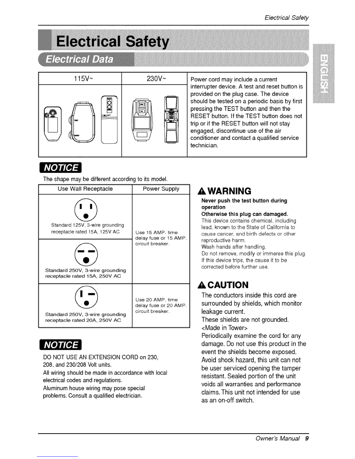
115V ~ 230V-- Power cord may"include a current:
interrupter device. A test and reset button is
pm,vided o,nthe plug case. The device,
sho,uld be tested on aperiodic b_is by first
pressing the TEST b_ton and then the
RESET button,, If the TEST b_to,n does not
tnp ,orif the RESET button will not stay
engaged, discontinue use of the air
conditioner and contact a qualified sewice
technid_.
The shoe may be dif_mnt according to _s mo,deL
Use Wall Receptacle
Stan_ 125V, 3-wre grounding
receptacle rata 15A, 125V AC
Stan_td 25OV, 3owite grounding
r_pita,c[e t'ated 15A, 2:5OV AC
Stand_d 2_V_ 3-wire, grounding
r_epitacle rated 20A, 2'_)V AC
Power Supply
U_ i5 AMP t_me
delay fu_ or '15 AMP,
circuit breaker,
Ug_ 20 AMP t_me
delay fu_ or 20 AMP,
circuit breaker
DO NOT USE AN EXTENSION CORD on 230,
_8, and 230/_8 Volt un_s..
AI_wiring sho,u_ be ma_ in accord_ce with local
electrical c_es _d reguiations.
Aluminum house wiring may _se sp_ial
proble,ms__nsu_ a qualifi_ electrician,
A WARNING
P@verpush the test button during
_hetwise this plug can damage,,
This device co_tains ,chemical, irr_cludir_g
iead, known to the State of California to
cause cancer, and birth defects or other
reproductive harm,
Wash ha_qds after handling.
_'_ not _emov'e, modify or immerse this p/u_3,
If this ,device trips, the cause it to be
corrected before fu_her use.
A CAUTION
The conduictors inside _is cord are
surrounded by shields, 'which monitor
leakage current
These shields are not grounded.
<Made in Tower>
Pefiodica.lly examine the cord for any
damage. Do not: use this product in the
event the shietds b_ome ex_s._,
Avo,id shock hazard, this unit can not
user serviced opening the tamer
#es.istant. Sealed portion of the unit
voids all warranties and pedo,rma.nce
claims. This unit not intend_ for use
as an on-off switch,
Ownerb Manual 9

(PLEASE READ CAREFULLY3
FOR' THE USER_ PERSONAL SAFET_ _IS
APPLIANCE MUST BE PROPERLY GROUNDED
The power cord of tir_isapp!iance is equipped with a
three-prong (grounding) piug. Use this with a standard
threes_ot (grounding) wal_ power out_et to minimize the
hazard of electdc sh_:ko The customer should have
the wa!l receptacle and circuit checked by a qualified
e_ectrician to make sure the receptacle is properiy
DO NOT CUT OR REMOVE THE THIRD (GROUND)
PRONG FROM THE POWER PLUG.
A. SITUATIONS WHEN THE APPLi_CE WILL BE
DISCONNECTED OCCASIONALLY:
Because of potentia_ safety hazards_ we strongly
dis_urage the use of a_ adapter p_ug. [However, if you
wish to use an adapter a "TEMPORARY
CONNECTION may be made. Use UL-listed adapter,
avai!ab/e from most _ocal hardware stores.
The !arge slot in the adapter must be aligned w}th the
large s_ot in the receptacle to assure a proper poladty
connection.
ACAUTION
: A_chingl the adapter ground |ermina| to the wall
recept_le cover screw does not ground the
alPP|mnceunle_ the cover screw is _tal, and not
insubt_, and the wall tentacle is grounded
through the hou_ wiring. The customer shou_
h_e the circuit checked by a qua|ified eleCt|clan to
_ke sulrethe r_ept_ie mproperly gmund_.
Disconnect the power ,_rd from the adapter, using
one hand on each, Otherwise, _e adapter ground
t,erminalmight break DO NOT USE the app%nce with
a broken adapter plug_
B. SITUATIONSWHENTHE APPL|ANCE WILL BE
DISCONNECTED OFTEN,
Do not:use an adapter plug in these situations.
Llnpiugging t:he power cord frequently can lead to an
eventua_ breakage of the ground terminal The wa_i
power outlet should be replaced by a threeos!ot
(grounding) outlet instead
USE OF EXTENSION _RDS
Because of potentia_ safety hazards we strongly
discoura_je the use ,ofar_extension cord. However. if
you wi_h to fuse a_ extension ,cord use a CSA
certi_iedULo_isted 3owire ,(grour_ding} extension cord,
rated at 15A, 125M
10 Room Air Coeditioner

tns_flation
Removepackingmaterialsfrom_e wallsleeveandtape
from theair _nditioner
INSTALLATIOI',I REQUIIREMENTS
If you fuse an exi_ing wall sl_ve, you should
measure its dimensions.
install the new air conditioner according to,the_e
installS:ion instructbns to achieve the best
pedorman_, AJl wal! s_ee'_s used to mount the new
air conditioner must _ in go_ stru_ural condition
and have a rear grill,e to securely attach the new air
conditioner. (FIG. 1)
With the, LGE s,leev_optiomally supp|l,ed with
your unit), you cart rr'aJint,ainthe best pe#orrr_n_ of
the new air conditioner (FIG. 2)
INSTALLATION HARDWARE
2 Size options
I_M I
NAMEOF PARTS Q%Y
PLASTICGRILLE 1
VERTICALiNSU_TiON STRIP 1
AROUNDINSULATIONSTRIPS 2
(_6 mini
ELECTRICAL SE_ICE
Check your avaii_aMe eIect[icM eerv_eo The _wer
su_ly _,_ailab_e must _ the same as 'l_hatshown on
the unit nameplate (_ound on le_ side of cabineO.
All! models _e equip_d with a 3-prong _rvice plug
to provi_ proper servi_ and _fe positive
grounding. Do not: change, plug in any way. Do not
use inn adapter p,[ug, if your present wall outlet do,_
Rot match your plug, call a qualified e[edrician to
make the necessary corrections. SAVE CARTON for
storage and this OWNER'S MANUAL for future
reference. The ca_ton is the best way to store unit
during winter o,r'when not in use,
To _voi,drisk of personal injery, prope_y
damage, or pme_ctr_damage due to the weight of
this device ,andsha_ _ges that:may
•._r conditioners covered in this manual _se an
ex_ssive weight h_d. _wo or more people are
n_ed to move and install the unit.
To prevent i_jury or strain, use proper iiflin9 and
carrying techniques when moving unit
• Carefully inspect location where air _ditio_er will
be instai_l_. Be sure it willsup_rt the weigN of
the unitover an extended period dtime.
• H_dle air conditioner with care.Wear prote_ive
gloves whenever li_in9 or carrying the unit.AVOID
the sharp metal fins dfront and rear coils..
•.Make sure air conditioner does not _1 during
installation.
REQUIRED TOOLS;
• Tight:Fitting gloves
• St.enda_rdscrewdriver
, Phillips screwdriver
• Pliers
• Sharp knife,
•3./8oincho_n end
wrench or adjustaMe
wrench
.,!/44rich hex socket
and ratchet
•T_e treasure
,,El_tdc ddll
,1/4-inch driUbit
Owne. s M_Riu_[ 11

Installation
CAUTION
We _rongly recommendthe removal,ofthe
oid wall sleeve and the installation of a new
LGE Wall Sleeve,
ilf you d_i_ to ke_ the existing wall sleeve,,
you have to redirect the Iou_ at the back of
the wall slee,,e illustration., The use of pliers is
re_mmended. If you DO NOT redir_t, you
run _e risk of p,_r _rform_ce 0,rproduct
failure. This isn,_ covered under the terms of
the LGE warranty.
• Pick a Ilooation which will_alilow the conditioned air
to b.l_w {nto the area you wan'L G_d installation
w_h _ecial attention to the proper p_it_,on of the
unit wil_ lessen the chance thi_ service will be
noed_.
_EMS IN iNSTALLATION HARDWARE
You may nolt ne_ all parts in the kit, Di_a_d unused
_arts
rrEM
Ve_ical insulation std_
Around Insulation Stri_
Horizontal insulation Str_ 23:%2 x l S..8x 1_.,_
_o_t B_ck 2
Baffle
Shim 11_sa6 x 1 xS_s 2
]"rim Frame 2
Washer Screw 4
Nuts(Plastic), 4
Grille Rear i
HOWTO INSTALL
_ _ntJfy the existing wall sieev_ b_fore [ns_Hing
the unit [tom the list_ _!o.w.
Brand ...........Wa_. .D.!._£_sion.s.
Wi_h
F_igidaite 25-1/2 15,,,,1/4 i 6, 17-i/2
or 22
Gener_ Electric 155/8 16o7/8
17-1/8
25o7/8 16q/2 or 2:3
27 163/4 16...3/4
or 19-3/4
25-7/8 t5-17/32 i6-2_'32
26-3/4 15-3/4 t5
25o3/4 16_7/8 18....5/8
Ried ri,ch 27 16-3/4 16-3/4
WhirIF_ol
Fed_rsiEmerson
LGE
Emerson/Fedders
A_Iwall sleeves used to, mount the new Air
Conditioner must be in sound structural condition
and ha_,,ea rear glrille that securely a_taches to,
sleeve, o,r rear flange that _rves as a stop tot the
Air Conditioner.
_ emor_ o,_dairconditionerfrom existingwail
sleeve.
_ lean the interbr or an ex sting sleeve.
(Do not disturb seals.)
Wall sleevemust be se'_Jrelyfastenedinwall
_{o,re ins_lin_gthe airconditioner.U_ the
naiiis or screws through sl_ve into wal_ if
nee_d. Repent sleeve it needed.
Prepare the wall sleeve for installlation of the
unit. if you plan to use your existing wa_I s_eeve,
and it is not LGE, use proc_u_e B or C bellow.
Proc_ure
,A
C ¸
B_and
LGE
White-Westin ghouse
Frigidaire Carrier
_52F series_
Gene, ra_ Electric
iHotpoint
Whirlpool
Carrier [51S _ries).
F_rsiEmier_3n
Emer_n/Fedders
Friedrich,
16o23/32
16, 17-1/2
or 22
16""7/8
17-!/8 or 23
18-5/8
16,-3/4
o,r !9,,,3/4
15
16,,,,,_'4
_ Install new unit intowallIsleeve.
CAUTION
When installation is _mpleted_ replacement unit
MUiS"T"ha_ a rearward slope as shovm. To
achieve !/4" s!ope, remo_e the _cking from the
1t13/t6" shim strips and aflach them as shown
_bw in Fig. 3. Place the higher portion of shim 1o,
the front: ot the rib on base of wall sbeve.
SH_ _ IJi_TINSTALLATION
FIIG.3
12 Room Air Conditioner

tns_'llation
PROCEDURE A
nH you are using the n_ sleeve (optionaHiy
sup,pried with your unit),s.kip to step 3.
Otherwise, install the pl_tic gdHe from the kit
Cut the plastic griIle to 25-!/2 '°wide and 15-
1/4 ° high, P_ace the plastic grille to the inside
of the walil s_eeve at the rear flange°
FiG, 4,
_ asten the 4 w_her _rews to, secure the grille
to the wall sleeve_ if you n_d plastic nuts to,
mount pfastic grille to the insi_ of the waWl
sleeve_ there are pl_tic nuts in the installation
kit. The nuts _e installed from the insi_ of _e
sleeve and a_e pressing into the square holes
o_the rear flanges.
FiG, 5
U emm_e the backing from the Vertical insulation
strip i5%6 x lS,8 × ls,s and attach that to the
inside right of the sl_ve as shown b,e_ow.
Remove the backing from the Around Insul_ion
strip, 67% x ! s8 x _5,s2and a_ach that to the
inside front of the s[leeve as shown _[Iow.
l_3or Outdoor
9 %" 6"
FiG. 6
U emove the metai re&r grille and repiace it with
the plastic rear gri!!e to improve unit energy
effid,ency, The plastic gr#le r_Juoes 'the amount of
hot air discharge that recircuiates through the unit
FIG. 7
_ Inst_f the new un_ into the wall sleeve
To.as_mble trim, snap the t_ of ,each piece
into the, slot et the other piece as shown below.
Slide trim over the front el the air conditioner
until trim is flush w_h sleeve _ shown _low.
Wall
FIG. 8
ACAUTION
,Air _nd_ioners covered inthis manua!pos_,an
excessive weight hazard, T_ or more people are
needed to move and instil the unit.
To prevent iniury or _r_n, use proper iifting and
carryingtechniqueswhenrowing unL
•When handling the air conditioner, be careM 1o
avoid cuts from sharp metai fins on Iront and rear
co!is,
• Make sure air conditioner ,doesno_ f_i during
remo_L
•Ifunff d_s not olpetate after insta!lation che_, to
sure the circuit inte_upter has not been tripped.
Rear te the Troubleshooting guide for reset
procedure.
iii_iiiiiiiiiiiiiiiiiiiiiiiii!iiiiiii/_
ii..................................................
ii_iiiii_iii_i_i_iiiiiiiiii!iiiiiiiii!iiiiii
IiIII
Owne, s M_niu_! 13

Installation
PROCEDURE Bi
_ _ired the lieuvers at the back of the wail
sleeve to 60 ° angle as. shown in the FIG 9. The
use of pliers is re_mmended_
I 7 !,bt
RearLo_vers
(Top View)
FIG,,'9
lf _e walil sleeve already has a rear gdlle, sMp
to step 4. if the walil slieeve does not ha_ a rear
9rilile or Iouvered panel, install the p_astic gdlle
from the kit. Cut the plastic grille to 25,°1/2" wide
and 15o!/4 " high. Place the plastic grille to the
inside of the wall sleeve at the rear flange.
Pia_ the plastic griliie FIG. t0
_ asten the 4 washer sc[ews to s_ure the grille
to the waft sleeve, if you need plastic nuts to
mount Ipiastic gri[ile to the inside of the wall
sleeve, there are plastic nuts in the insta_fation
kit. The nuts are insta[f_ from the inside of the
sleeve, and arre pieced into the square holes oil
the rear flanges.
Fasten the screws FiG. 11
DRemove the backing from the Vertical insulation
strip, 15%,s x 1_,,_x ! _,'_and attach that to the
inside right dthe steeve as shown _1_,
Remove the backing from the Around Insulation
strip 67% x 1_,,_x _ and attach that fo _e
inside #ont ,ofthe sleeve as,shown below.
_door Outdoor
F_G. 12
_ emove the, metai rear gri!le and replace it with
the plastic rear grille to imDove unit energy
effiiciency_ The plastic grille r_uces the amount
of hot air discha_-ge tihat reciirculates through the
unit,
FIG. !3
ff the _pth of your existing wall slee_ is less
than or equal to 18," skip to step, 7, Otherwise
cut the _tfles and the su_ort Mocks according
to [e,ngth "A" in the table be_o,w.
Depth_D_'ofthe exi_ing
wallsleeve(inches)
19-_/_<D_< 22
Length"A"
3/4
13/4
4
14 Room Air Coinditionief

PROCEDURE B
installation
as sh_vn FIG 15. Slide the baffle intoslots of
the su_,ort Mocks
Wall
Wall--
Sleeve
_Install the n_ unit into the w.all s_eove.
_ ssemble, trim as describ_ in Step &
Proc_ure A..
,,Air_ndition,ers cover_ in this manualpo_ an
excessiveHight hazard,T_ or morepeopleare
need_ 1omoveand in_aiiltheunit.
useproper liRingand
movingun_.
coils.
* Makesureair condRionerdoesnot fal_duriag
removal
* If uait _es notoperateafterinsta!lationcheck,to be
procedure.
r _Owne, s MaRiua[ 15

instalia#on
PROCEDURE C
_ R_iro_ the louvers at the back of the wa_l
sleeve to 60 ° angle as, shown in the FIG 16
The u_ of pliers is, r_ommen_d,
7 _
Rea_Louvers
(Top View)
FIG. 16
lf _e wall sleeve already has a rear gdHe sMp
to step 4. if the walil sleeve d_s not have a rear
9rilile or ]ouvered pane], install the plastic gdlle
fm,m the kit. Cut the plastic gdlle to 26-1/2" wide
and 15o!/2 " high. Place the plastic grille ilo the
inside of the-wail sleeve at the rear flange.
Place the plastic grille F_G. 17
_ asten the, 4 washer sc[_s to s_ure the grille
to the wall sliec</e, if yes need plastic nu_ to
mount plastic 9riIIle to the inside of the walil
sleeve, there are plastic nuts in the installation
kit. The nuts are insta]l_ from the inside of the
sleeve and are pressed into the square holes of
the rear flanges,
Fasten the screws; FIG. 18,
Remove the ba,_ing from the Horizontal
_nsulatioin strip 23h:32x 138 x 13,_ and attach
that to the inside right of the sleeve as shown
_low. Remove the ba_.ing from the A_ound
Ins,ulatioin strip 59_h,_2x: 1% x 1% and attach
that t,o the inside front of the slee.te ,as shce_n
_low.
Indoor Out.or q
8 _
HG. t9
[1the _pth of you_ existing sleeve is less than
or equal to 18", sk_ to step 7. _ePwise, cu_
the baf|l_ and the support b_oc_ according to
Length 'W' in the table _]ow,
Oepth_'D'' of the ,existing Length "A°
18 <D _<18_% s/4
18o%<O_19_/_ 13/4
_ emo_ the ba_ing kom the supF:_rt b!lks
and a'_a,ch them to the inside of the wall sleeve
as shown FIG 2'1 Sli@_ the baffle into, sk_ts of
the snppo,# blocks
WS|_
Sleeve
16 Room Air CoinditJonier

Ins_'llation
PROCEDURE C
liil To achieve rearward slo_ [or unit draining,
remove the backing from the 11_s_,l_"shim
strips and attach them as shown below in Fig,
23° The higher portion of shim is to be pliaced
in front of the rib, on the base of wall s[eeveo
FiG. 22
& CAUTION
• Air,_nditioners coveredin this imianua[_e an
,excessiveweigN hazard,T_ ,ormorepeopleare
need_ to m,o_ and instaiithe unit,
•Whenhandlingtheair conditioner,be carefu!to avoid
,cutsfrom sharp metalfins on frontand rearcoils,
• Makesureair cond_ionerdoes notfaliduring
rem0vaL
• If unit_es notoperateafter installationcheck,to be
FIG,,2:3
D Remove the metal rear grille and rep.lace it with
'the plastic rear grille to impro,,® unit energy
efticiency. The plastic gri]fe reduces the amount
of hot air discharge that tecirculates through the
unit:
FIG. 24
_Install the new unit into the wall slee_Je
_ ssemb!,e trim as _scribed in St_ 6,
Precedure A,
r _Owne, s MaRiua[ 1Z

Operatingtnstrucfions
'Thecontrols wilt leek like on of the fottowi_,
,--FAN SPEED
, Every time you push this button_itadvances the _tting as follows: {High-, Low-_M_ -_ High}
REMOTE CONTROL SIGNAL
TEMPERATURE S_ING
- Use this b_n to automati_Hy control the
tem_rature dthe room.
T_ tem_rature _n be ss_within a range d
@'_Fto ,_F by increments 0'f !'_F
- The setti% a_a_s in _e display.
-START TiME
* Ifunit is off use Time__oset:num_ dt'¢ou__fore unit stads
*Push Timer _on to advance _ng from 1Hour 2Hours _.
-_ '12Hou[smaximum
"- MODE
Push this _J_On_oshi_ me® doperation from COOL -_ ENERGYSAV_R -, FAN.
-COOL:
,F_ runs continuaJlly for normal cooling o_ration
-ENERGY SAVER:
*To turn _e air conditione_ON, push D_sbu_on.
Totum the air co_itioner OFF #Jsh the _on
- ThisbuttontakesFiorityover_qy,otherbutton
-When'youfirst:turn_on_theunitisincool
mode,Highfans_ed Tem_raturese_ingat
72.OF
.Thefan_b[>._w_n t_ .comFessot_b_ c_iag Ap#=oximately.every3 miinutost_ 'fanwill_rn on and_e uni_.will
ct_ck tt_ roomai_tem_raturetodet,e_mineifcecil% isne_ed
-FAN:
•F_-only operation,,
afl_ an ,electrical _wer faflure_ the unit will begin to run at Rs last setti_
18 Room ALr Conditioner

OperatingInstructions
The remote control ar_ control p_et will look like oi_ of the' _O'_OJW_ pictures.
- To turn the air dJ_ditioner ON, push this buIton.
To turn the air c_nditione_ OFF, push the button again
- This but,ton takes priod'ly over any other buttor_.
- When you firs1 t_m it on, the unit is in (#o_ m(_e, High fan spe_J_
Temperature setting a 7_F,
. Auto Resta_
_nthe event at a power failure, the unit will run a the previous setting once
power returns.
TEM PERATURE SE_ NG
• Usethis bf_tton_oautomatically_ntrol the tempe_lure of the room
Thetem_rature can be set 'withina range of 60°F to 86°F by
increments d1_F
, The se%% appe_s in the display
FAN SPEED
• Everytime you pf_shthis bu_on it adv_s the setting asfollows
(High--* Low-_ Med-_ High}
TIMER
- SHUT,-OFFT_ME
•You will usu_iy use shut-offtime whiie you sleep.
• if unit is running,u_ Timer to set numL_rof hoursuntii shut-off
. FOryour sleeping comfort,once,Time is set,the Temperature setting will
raise2_Fafter 30 rain, and once again after anolher 30 rain,
•PushTimer button to advan_ sefling from 1Hour,_ 2Hours .....,,,
12Hours maximum
-START T_ME
•/f unit is off, u_ Timer toset o_hours before un_sfa_s.
• PushTimer buttonto adv_ s_ing from 1Hour-, 2Hours -, .. -_
12Hoursmaximum.
- Pushthis bu_on to shift mode of o_ration from COOL ......ENERGY SAVER ....FAN,
oCOOL:
• Fanruns con'Ii_qual_y_ornormalcooling o_ration,
- ENERGY SAVER:
• The fan stopswhen the compressor stopscoo_ing,Approximalely eveq,,3 minutesthe fanwill turn on
and the unitw_lloh_k the room airtemperature to determine if cooling isneeded.
FAN:
- Fan-onlyo_rat_on
r _Owne, s MaRiua[ 19

Operatinginstructions
1 Remove the ,co_erfrom the back of _e remote
_ntroller
2. Insert two batteries.
, Be sure that the, (+) and (-) dire_ions are
eorrect,
• Be sure that both batteries are new.
3. Re-attach the cover.
,. Do not use r_harg,eaNe b,a_eries
Such _tteries ditfer from stand_d
dry ce!lls in sh_e_ di_nsions, and
_rformance.
• Re_ve the batteries from the
remote control!let if the air
_nditio,ner is not going to,b,eused
br _ exten_d len_h of time,
The ventilation _everis _ocat_ in the right ,ofthe air' discharge_
The ventilation _eJermust be in the CLOSE position in order to
m_ntain the best cooling condit_,ons,
'When fresh _r is neces_ry in the r_m, set the ven'_ation le/er to
the OPEN _sition
The damper is opened and room air is exhausted outside. I
PULL OPEN /PUSH CLUE
i ii i_i
The dire_ion of air can be _ntrol_ed where_r you wantby adjusting the horizontal louver and the ve_ic_ buver.
• TAL A, TION *VERTICAL ,A TION CONTROL
The ho,rizonta] _r direction isadjured Ibymoving
verticall louver.
The !,eve_of vertical louver is I_ed in the right and
[eft side of the .airdischarge.
The vertic_ _r direction is adjusted by moving the
horizontal louver.
20 Room Air Conditioner
This manual suits for next models
2
Table of contents
Other LG Air Conditioner manuals
Popular Air Conditioner manuals by other brands

CLIMAVENETA
CLIMAVENETA a-CHD U-2T 606+2209 OPERATING AND INSTALLATION Manual

Mitsubishi Electric
Mitsubishi Electric Mr.Slim MSZ-A24NA operating instructions

York
York F2FP040H06 User's information manual

Argo
Argo SWAN EVO operating instructions

S2P
S2P KS2P-18C210 owner's manual

Innova
Innova IGZCAPS NI Series owner's manual

Samsung
Samsung AC024JXADCH installation manual

Bard
Bard THE WALL-MOUNT WA3S3-A installation instructions

Infiniton
Infiniton SPLIT-3725DM Owner's manual & installation manual

Daikin
Daikin FXFQ07TVJU Operation manual

Mitsubishi Electric
Mitsubishi Electric City Multi PLFY-WL-VEM-E Series installation manual

Samsung
Samsung AQ09F Series user manual