14 |WSU PRODUCT DATA WSU PRODUCT DATA | 15
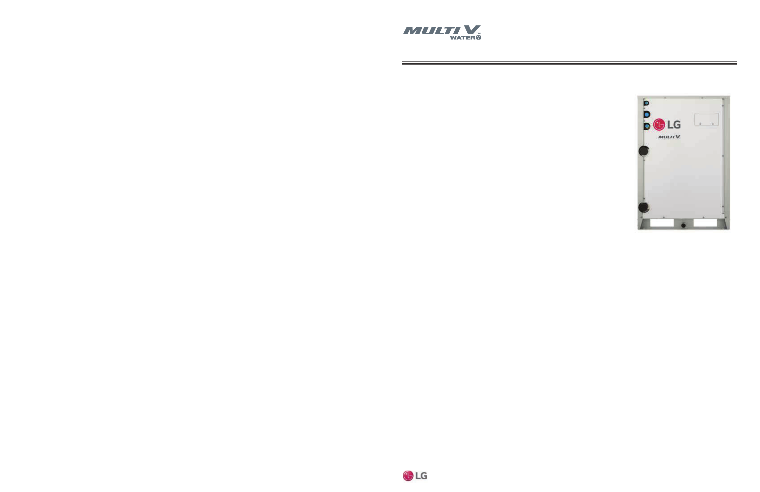
Water Source Unit Product Data
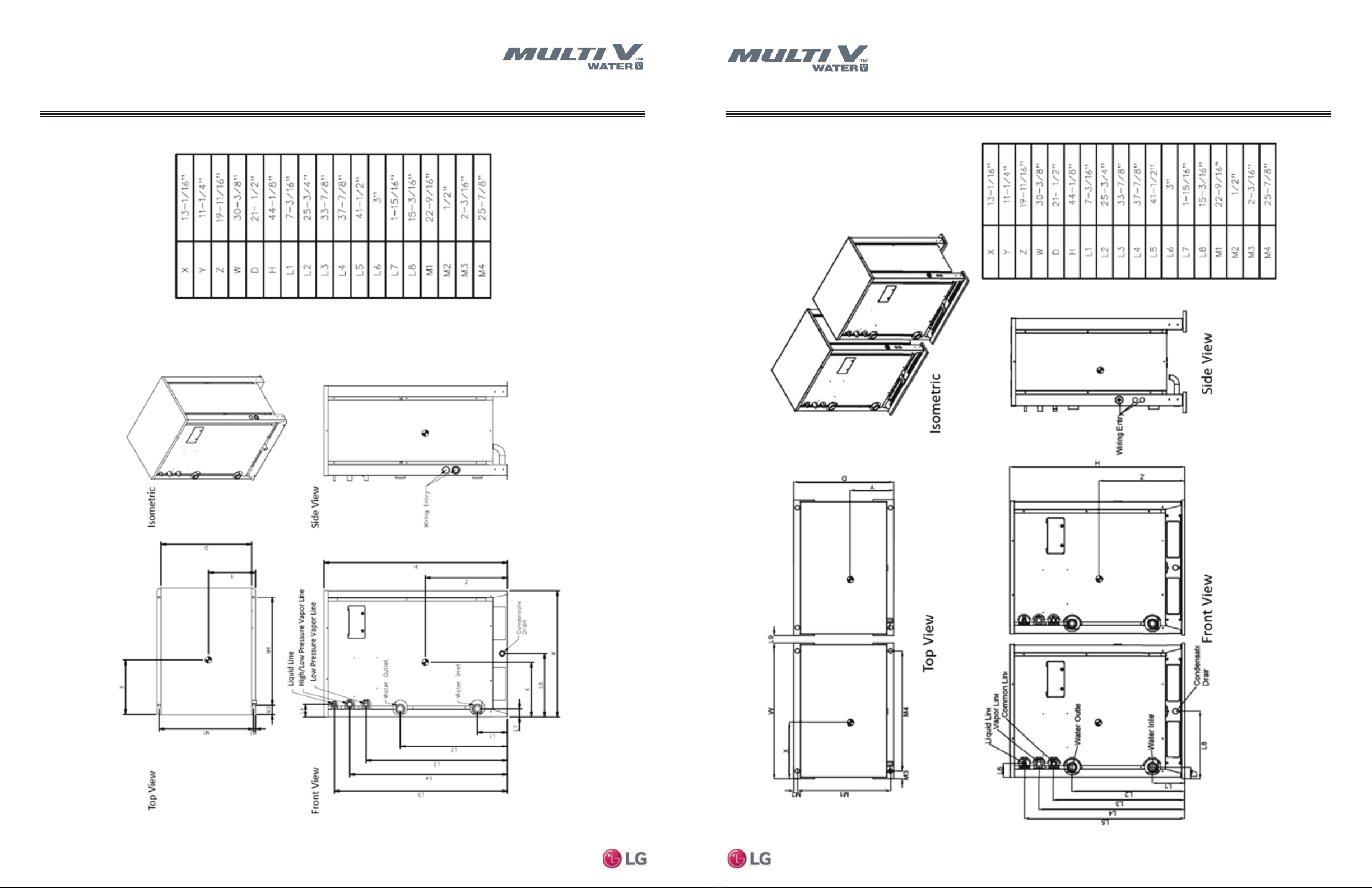
MULTI V Water V Water Source Unit Engineering Manual
© LG Electronics Canada, Inc., North York, ON Canada. All rights reserved. “LG” is a registered trademark of LG Corp. © LG Electronics Canada, Inc., North York, ON Canada. All rights reserved. “LG” is a registered trademark of LG Corp.
Table 2: Multi V Water V 575V Units
Combination Unit Model Number 20.0
ARWM240CAS5
24.0
ARWM288CAS5
28.0 Ton
ARWM336CAS5
Individual Component Model Numbers ARWM096CAS5 x 1
ARWM144CAS5 x 1 ARWM144CAS5 x 2 ARWM144CAS5 +
ARWM192CAS5
Cooling Performance
Nominal Cooling Capacity (Btu/h)1239,400 287,700 336,000
Heating Performance
Nominal Heating Capacity (Btu/h)1269,000 324,000 378,000
Operating Range (Entering Water Temperature)
Cooling (°F)223 – 113 23 – 113 23 – 113
Heating (°F) 14 – 113 14 – 113 14 – 113
Synchronous Operation (°F) 23 – 113 23 – 113 23 – 113
Compressor
Inverter Quantity HSS DC Scroll x 2
Oil/Type PVE/FVC68D
Unit Data
Refrigerant Type R410A
R410A Refrigerant Factory Charge (lbs) 9.9 + 9.9 9.9 + 9.9 9.9 + 9.9
Refrigerant Control/Location EEV/Indoor Unit
Max. Number Indoor Units/System239 45 55
Sound Pressure dB(A)3 Cooling/Heating 55 57 59
Net Unit Weight (lbs.) 348 + 348 348 + 348 348 + 348 309 + 309
Shipping Weight (lbs.) 370 + 370 370 + 370 370 + 370
Communication Cables5,6 2 x 18 AWG
Heat Exchanger (Stainless Steel Plate)
Maximum Pressure Resistance (psi) 640 640 640
Flow at Rated Condition (GPM) 25.4 + 35.5 35.5 + 35.5 35.5 + 50.7
Range of Flow (GPM) 30.5 – 91.4 35.5 - 106.5 43.1 - 129.3
Total Heat of Rejection (Btu/h) 316,000 380,200 443,600
Total Heat of Absorption (Btu/h) 245,400 293,600 340,400
Pressure Drop (ft-wg) 3.51 + 6.50 6.50 + 6.50 6.50 + 12.61
Δt4(°F) 10.4 10.7 10.3
Piping for Heat Recovery Operation7
Liquid Line Connection (in., OD) 3/8 + 1/2 Braze 1/2 + 1/2 Braze 1/2 + 5/8 Braze
Low Pressure Vapor Line Conn (in., OD) 7/8 + 1-1/8 Braze 1-1/8 + 1-1/8 Braze 1-1/8 + 1-1/8 Braze
High Pressure Vapor Line Conn (in., OD) 3/4 + 7/8 Braze 7/8 + 7/8 Braze 7/8 + 1-1/8 Braze
Piping for Heat Pump Operation7
Liquid Line Connection (in., OD) 3/8 + 1/2 Braze 1/2 + 1/2 Braze 5/8 + 5/8 Braze
Low Pressure Vapor Line Conn (in., OD) 7/8 + 1-1/8 Braze 1-1/8 + 1-1/8 Braze 1-1/8 + 1-1/8 Braze
Piping for Water7
Water Inlet/Outlet Connection Size (in) (1-1/2 + 1-1/2 Fem) x2 (1-1/2 + 1-1/2 Fem) x2 (1-1/2 + 1-1/2 Fem) x2
Condensate Drain (in) 3/4 Female 3/4 Female 3/4 Female
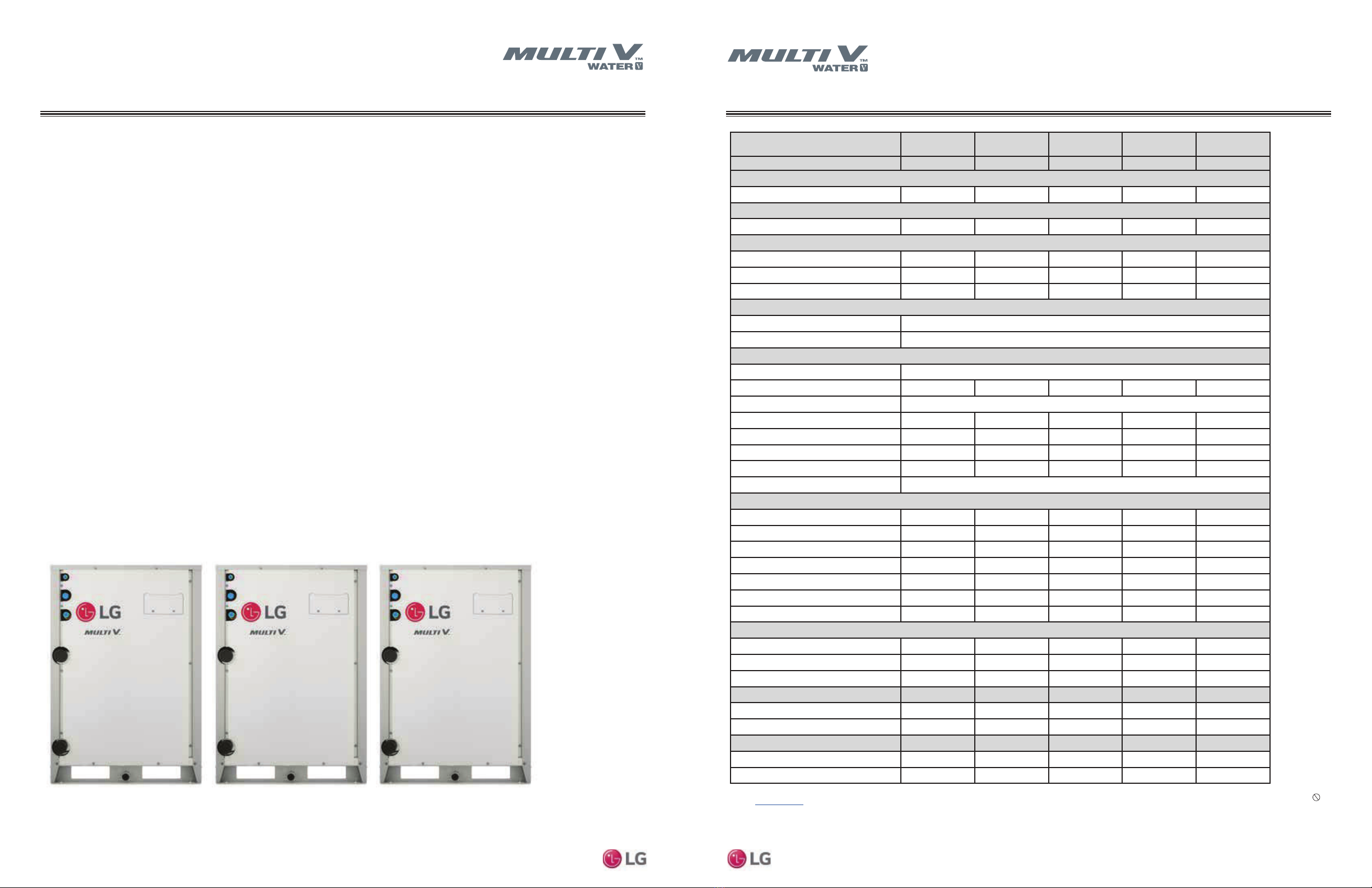
Multi V Water V 575V Unit Specications
GENERAL DATA
1 Rated capacity is certified under AHRI Standard 1230. Ratings are subject to change without notice. Current certified ratings are
available at www.ahridirectory.org.
2 When entering water temperature is lower than 59ºF, variable water flow control kit PWFCKN000 is required.
3 Sound pressure levels are tested in an anechoic chamber under ISO 3745 standard.
4 Value is calculated as follows: Δt = Total Heat of Rejection/(Nominal Flow Rate x 500).
5 Communication cable between Master ODU to Slave ODU(s), and Master ODU to IDUs / HRUs to be 18 AWG, 2-conductor,
twisted, stranded, shielded. Ensure the communication cable shield is properly grounded to the Master ODU chassis only.
Do not ground the ODU to IDUs / HRUs communication cable at any other point. Wiring must comply with all applicable local and
national codes.
6 Power wiring is field provided, solid or stranded, and must comply with the applicable local and national codes.
7 LG requires that LATS software be used on all projects to ensure correct line sizing. Designer must verify the shop drawing design
against the as built design using LATS. Contractor must also use LG manufactured Y-Branch and Header Kits only.
Table 3: Multi V Water V 575V Units
Combination Unit Model Number 36.0 Ton
ARWM432CAS5
40.0 Ton
ARWM480CAS5
48.0
ARWM576CAS5
Individual Component Model Numbers ARWM144CAS5 x 3 ARWM144CAS5 x 2
+ARWM192CAS5 x 1 ARWM192CAS5 x 3
Cooling Performance
Nominal Cooling Capacity (Btu/h)1430,500 472,500 571,200
Heating Performance
Nominal Heating Capacity (Btu/h)1486,000 536,000 642,000
Operating Range (Entering Water Temperature)
Cooling (°F)223 – 113 23 – 113 23 – 113
Heating (°F) 14 – 113 14 – 113 14 – 113
Synchronous Operation (°F) 23 – 113 23 – 113 23 – 113
Compressor
Inverter Quantity HSS DC Scroll x 3
Oil/Type PVE/FVC68D
Unit Data
Refrigerant Type R410A
R410A Refrigerant Factory Charge (lbs) 9.9 + 9.9 + 9.9 9.9 + 9.9 + 9.9 9.9 + 9.9 + 9.9
Refrigerant Control/Location EEV/Indoor Unit
Max. Number Indoor Units/System264 64 64
Sound Pressure dB(A)3 Cooling/Heating 59 61 63
Net Unit Weight (lbs.) 348 + 348 + 348 348 + 348 + 348 348 + 348 + 348
Shipping Weight (lbs.) 370 + 370 + 370 370 + 370 + 370 370 + 370 + 370
Communication Cables5,6 2 x 18 AWG
Heat Exchanger (Stainless Steel Plate)
Maximum Pressure Resistance (psi) 640 640 640
Flow at Rated Condition (GPM) 35.5 + 35.5 + 35.5 35.5 + 35.5 + 50.7 50.7 + 50.7 + 50.7
Range of Flow (GPM) 53.3 - 159.8 60.9 – 182.6 76.1 – 228.2
Total Heat of Rejection (Btu/h) 570,300 633,700 760,500
Total Heat of Absorption (Btu/h) 440,400 487,200 580,800
Pressure Drop (ft-wg) 6.50 + 6.50 + 6.50 6.50 + 6.50 + 12.61 12.61 + 12.61 + 12.61
Δt4(°F) 10.7 10.4 10.0
Piping for Heat Recovery Operation7
Liquid Line Connection (in., OD) 1/2 + 1/2 + 1/2 Braze 1/2 + 1/2 + 5/8 Braze 5/8 + 5/8 + 5/8 Braze
Low Pressure Vapor Line Conn (in., OD) 1-1/8 + 1-1/8 + 1-1/8 Braze 1-1/8 + 1-1/8 + 1-1/8 Braze 1-1/8 + 1-1/8 + 1-1/8 Braze
High Pressure Vapor Line Conn (in., OD) 7/8 + 7/8 + 7/8 Braze 7/8 + 7/8 + 1-1/8 Braze 1-1/8 + 1-1/8 + 1-1/8 Braze
Piping for Heat Pump Operation7
Liquid Line Connection (in., OD) 1/2 + 1/2 + 1/2 Braze 1/2 + 1/2 + 5/8 Braze 5/8 + 5/8 + 5/8 Braze
Low Pressure Vapor Line Conn (in., OD) 1-1/8 + 1-1/8 + 1-1/8 Braze 1-1/8 + 1-1/8 + 1-1/8 Braze 1-1/8 + 1-1/8 + 1-1/8 Braze
Piping for Water7
Water Inlet/Outlet Connection Size (in) (1-1/2 + 1-1/2 Fem) x3 (1-1/2 + 1-1/2 Fem) x3 (1-1/2 + 1-1/2 Fem) x3
Condensate Drain (in) 3/4 Female 3/4 Female 3/4 Female
Multi V Water V 575V Unit Specications
GENERAL DATA
1 Rated capacity is certified under AHRI Standard 1230. Ratings are subject to change without notice. Current certified
ratings are available at www.ahridirectory.org.
2 When entering water temperature is lower than 59ºF, variable water flow control kit PWFCKN000 is required.
3 Sound pressure levels are tested in an anechoic chamber under ISO 3745 standard.
4 Value is calculated as follows: Δt = Total Heat of Rejection/(Nominal Flow Rate x 500).
5 Communication cable between Master ODU to Slave ODU(s), and Master ODU to IDUs / HRUs to be 18 AWG, 2-con-
ductor, twisted, stranded, shielded. Ensure the communication cable shield is properly grounded to the Master ODU
chassis only. Do not ground the ODU to IDUs / HRUs communication cable at any other point. Wiring must comply
with all applicable local and national codes.
6 Power wiring is field provided, solid or stranded, and must comply with the applicable local and national codes.
7 LG requires that LATS software be used on all projects to ensure correct line sizing. Designer must verify the shop
drawing design against the as built design using LATS. Contractor must also use LG manufactured Y-Branch and Header
Kits only.


 null")