LG MFL65003102 User manual

INSTALLATION MANUAL
AIR CONDITIONER
• Please read this installation manual completely before installing the product.
• Installation work must be performed in accordance with the national wiring
standards by authorized personnel only.
• Please retain this installation manual for future reference after reading
it thoroughly.
P/NO : MFL65003102 www.lg.com
TYPE: Vertical Air Handling Unit
ENGLISH FRANÇAIS ESPAÑOL

2Vertical Air Handling Unit

Installation Manual 3
ENGLISH
Vertical Air Handling Unit Installation Manual
TABLE OF CONTENTS
❏Four type "A" screws
❏Pipes: Gas side
Liquid side (Refer to
Product Data)
❏Insulation materials
❏Additional drain pipe
❏Level gauge
❏Screw driver
❏Electric drill
❏Hole core drill
❏Hexagonal wrench
❏Gas-leak detector
❏Vacuum pump
❏Gauge manifold
❏Owner's manual
❏Thermometer
❏Electric Heater installation
manual
Features ......................................4
Accessories ..............................4
Duct Connection Dimensions ..5
Safety Precautions....................6
Installation ..................................8
Selection of the best location ...8
Upflow Installation ....................9
Duct work................................10
Horizontal-left Installation .......11
Connecting Pipes to the Indoor
Unit ..........................................12
Preparation of Piping..............12
Insulation.................................15
Condensate Drain ..................16
Wiring Connection..................18
Installation of Wired Remote
Controller ................................20
Name and function of wired
remote controller(Accessory).22
Name and function of wireless
remote controller(Accessory).23
Electric Heater ........................24
Dip Switch Setting of Indoor unit
PCB.........................................25
Group Control Setting ............26
How to Set E.S.P? ...................30
Product Data ............................32
External Static Pressure & Air
Flow.........................................32
Minimum airflow by heater
capacity...................................33
Electric Heater Static pressure
drop factors.............................33
Air Filter (Field supply) Static
pressure drop factors .............34
Installation Requirements Required Parts Required Tools

Wiring knockouts
for conduit
Wiring knockouts
for conduit
Refrigerant
connections
Drain connections
for horizontal
application
Filter access Drain connections for
upflow application
Feature
Accessories
Accessory Model Name
Wired remote controller PQRCVSL0 (Black Color)
PQRCVSL0QW (White Color)
Wireless remote controller PQWRCDF0 (Heat pump)
PQWRHDF0 (Cooling only)
Electric heater
ANEH053B1
ANEH103B2
ANEH153B2
ANEH203B2
4Vertical Air Handling Unit
Features

ENGLISH
Feature
Installation Manual 5
Duct Connection Dimensions
<Top>
<Front>
<Bottom>
<Side-right>
Refrigerant
connections
Drain connections
for horizontal
application
Drain
connections
for upflow
application
Air filter cover
(Unit: inch(mm))
Capacity
(kBtu/h (RT))
Dimensions Wiring
Knock out Refrigerant
Connections
Pipe size
A B C
D E F G H
I J
Height Width Depth Power Commu
nication Liquid Gas
18(1.5) 48-5/8
(1236)
18
(457)
21-3/8
(540)
1-9/16
(40)
17-1/2
(445)
20
(530)
17
(432)
12-1/8
(308)
1-11/16
(43)
7/8
(22)
1/4
(6.35)
1/2
(12.7)
24(2.0)
30(2.5)
36(3.0)
48-5/8
(1236)
18
(457)
21-3/8
(540)
1-9/16
(40)
17-1/2
(445)
20
(530)
17
(432)
12-1/8
(308)
1-11/16
(43)
7/8
(22)
3/8
(9.52)
5/8
(15.88)
42(3.5)
48(4.0)
54(4.5)
55-1/8
(1401)
25
(635)
21-3/8
(540)
1-9/16
(40)
24-1/2
(623)
20
(530)
24
(610)
12-1/8
(308)
1-11/16
(43)
7/8
(22)
3/8
(9.52)
5/8
(15.88)

Safety Precautions
Safety Precautions
To prevent injury to the user or other people and property damage, the following instructions must be followed.
■Be sure to read before installing the air conditioner.
■Be sure to observe the cautions specified here as they include important items related to safety.
■Incorrect operation due to ignoring instruction will cause harm or damage. The seriousness is classified by the
following indications.
■Meanings of symbols used in this manual are as shown below.
This symbol indicates the possibility of death or serious injury.
This symbol indicates the possibility of injury or damage to properties only.
Be sure not to do.
Be sure to follow the instruction.
■Installation
Do not use a defective or
underrated circuit breaker.
Use this appliance on a dedi-
cated circuit.
• There is risk of fire or electric
shock.
For electrical work, contact
the dealer, seller, a qualified
electrician, or an Authorized
Service Center.
• Do not disassemble or repair
the product. There is risk of
fire or electric shock.
Always ground the product.
• There is risk of fire or electric
shock.
Install the panel and the
cover of control box securely.
• There is risk of fire or electric
shock.
Always install a dedicated
circuit and breaker.
• Improper wiring or installation
may cause fire or electric
shock.
Use the correctly rated break-
er or fuse.
• There is risk of fire or electric
shock.
Do not modify or extend the
power cable.
• There is risk of fire or electric
shock.
Do not let the air conditioner
run for a long time when the
humidity is very high and a
door or a window is left open.
• Moisture may condense and
wet or damage furniture.
Be cautious when unpacking
and installing the product.
• Sharp edges could cause
injury. Be especially careful of
the case edges and the fins
on the condenser and evapo-
rator.
6Vertical Air Handling Unit

■Installation
Always check for gas (refrig-
erant) leakage after installa-
tion or repair of product.
• Low refrigerant levels may
cause failure of product.
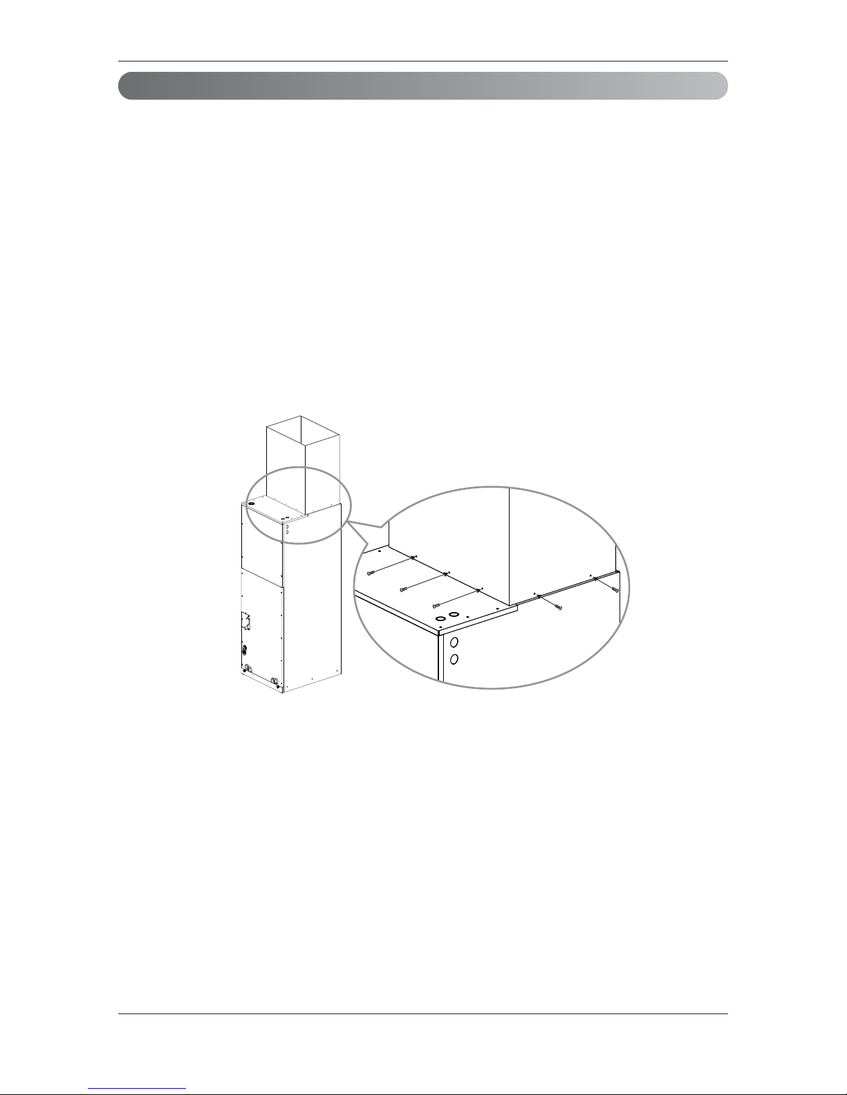
Install the drain hose to
ensure that water is drained
away properly.
• A bad connection may cause
water leakage.
Keep level even when
installing the product.
• To avoid vibration or water
leakage.
Do not install the product
where the noise or hot air from
the outdoor unit could dam-
age the neighborhoods.
• It may cause a problem for your
neighbors.
Use two or more people to lift
and transport the product.
• Avoid personal injury.
Do not install the product
where it will be exposed to
sea wind (salt spray) directly.
• It may cause corrosion on the
product. Corrosion, particularly on
the condenser and evaporator
fins, could cause product malfunc-
tion or inefficient operation.
If you eat the liquid from the
batteries, brush your teeth and see doctor. Do
not use the remote if the batteries have leaked.
• The chemicals in batteries could cause burns or
other health hazards.
Safely dispose of the packing materials.
• Packing materials, such as nails and other metal or
wooden parts, may cause stabs or other injuries.
• Tear apart and throw away plastic packaging bags
so that children may not play with them. If children
play with a plastic bag which was not torn apart,
they face the risk of suffocation.
Safety Precautions
■Operation
For installation, always con-
tact the dealer or an
Authorized Service Center.
• There is risk of fire, electric
shock, explosion, or injury.
Do not install the product on
a defective installation stand.
• It may cause injury, accident,
or damage to the product.
Be sure the installation area
does not deteriorate with age.
• If the base collapses, the air
conditioner could fall with it,
causing property damage,
product failure, and personal
injury.
Do not store or use flammable gas or combustibles near the product.
• There is risk of fire or failure of product.
ENGLISH
Installation Manual 7

Installation
• Where optimum air distribution can be ensured.
• Where nothing blocks air passage and install the duct work.
• Where condensate can be properly drained.
• Where the ceiling is strong enough to bear the indoor unit weight.
• Where the false ceiling is not noticeably on an incline.
• Where sufficient clearance for maintenance and service can be ensured.
• Where piping between indoor and outdoor units is possible within the allowable limit. Refer to the
installation manual for the outdoor unit.
• Vertical Air Handling Unit can be installed for upflow and horizontal-left positions.
NOTE : The primary and secondary drain line must be trapped to allow proper drainage of condensate
water, If the secondary drain line is not used, it must be capped.
Selection of the best location
More than 23-5/8 inch
(600 mm)
clearance from
access panels
for Service
More than
10 inch
(250mm)
More than
10 inch
(250mm)
More than 14 inch
(350 mm)
More than 14 inch
(350 mm)
In the case of sea coast installation, salt residue may cause corrosion of cabinet and component
parts. Please take appropriate anti-corrosion measures.
8Vertical Air Handling Unit
Installation

• Position unit for plenum installation.
• The plenum should be secured in order to support the installation of adapter callers accommodate the
installation of any duct work.
• Seal all duct work according to local codes to prevent air leakage. Ensure that filter access is unob-
structed.
• The air handler support platform should be sturdy enough to support the cabinet plus any accessory
components including filter box.
• The minimum height clearance is 14inches(350mm) to maintain proper air flow.
• Vibration isolators (purchased locally) must be placed between the unit and the pedestal.
• An illustration showing an example of where a vibration isolator should be added would clarify what
the installing contractor should do to properly position the isolator.
More than 6 screws (M4*25L)
Field
Supplied Return
Plenum
More than
1inch (25mm)
Field Supplied
Supply Duct
Installation
Upflow Installation
Do not connect the screws on Front and Rear side, it may cause the filter can not be mounted.
ENGLISH
Installation Manual 9

10 Vertical Air Handling Unit
Installation
Duct work
• Over 10 screws should be used for joining supply duct with the unit.
• To prevent vibration transmission, exploit flexible connectors between duct and the unit. It is mandato-
ry that the flexible connector between unit and duct at discharge connection should be made off heat
resistive material when electric heater is installed.
• Duct work must be insulated and covered with vapor barrier when routed through unconditioned
space.
• Internal acoustical insulation lining may necessary for the metal duct system if it do not have 90°
elbow and 10ft. of main duct to first branch takeoff.
• It is advised that a fibrous duct work could be used as a substitute if built and installed in accordance
with the most recent edition of SMACNA construction standard on fibrous glass ducts.
• Collectively fibrous duct work and acoustical lining shall obey National Fire Protection Association
standards 90A or B as tested by UL standard 181 for class 1 air ducts.
• Seal around the delivery duct subsequent to when the duct is secured so that to facilitate prevention
of air leakage.
More than 10 screws
(M4*25L)

Installation Manual 11
ENGLISH
• It is particular that the units should not be installed in such a manner that the access panels facing up
or down
• It should be confirmed that the installation is in accordance with all relevant building codes that may
necessitate installation of external condensate pan.
-Set up a support for unit by locating it in or above external condensate pan.
• Angle steel support brackets with threaded rods which supporting the units from the underside should
be used as shown in the figure below if the units are suspended.
• If not suspended then also it should be supported as same as mentioned above and also carefully
isolated to avoid sound transmission. The size of the support should comparatively bigger than the
unit and the unit must be place at centre of the support.
• Locally available vibration isolators must be placed between the unit and the support.
• The same installation method of up flow type has to be used in the case of Return Plenum and sup-
ply duct.
Installation
Horizontal-left Installation
To ensure proper drainage for horizontal installations, unit must be installed so it is within 1/8” level of
the length and width of unit.
BA
C
More than 1-1/2
inch(38 mm) X 1-1/2
inch(38 mm) angle
Recommended
length more than 26
inch(660 mm) with
2 inch(50 mm)
clearance on both
sides of unit
More than 3/8 inch
(9.5mm) threaded rod
Field Supplied
Supply Duct
Field Supplied
Return Plenum
Suspension support locations
Caapcity
(kBtu(RT))
Dimension
ABC
18(1.5)
24(2.0)
30(2.5)
36(3.0)
4(100) 23(580) 41-1/2
(1050)
42(3.5)
48(4.0)
54(4.5)
4(100) 29(730) 48(1220)
(Unit : inch(mm))

Installation
Preparation of Piping
Cut the pipes
1. Use the pipes purchased locally.
2. Measure the distance between the indoor and the outdoor unit.
3. Cut the pipes a little longer than measured distance.
Burrs removal
1. Completely remove all burrs from the cut cross section of pipe/tube.
2. While removing burrs put the end of the copper tube/pipe in a downward direction while removing
burrs location is also changed in order to avoid dropping burrs into the tubing.
Copper
pipe
90°
Slanted Uneven Rough
Pipe
Reamer
Point down
Connecting Pipes to the Indoor Unit
Cutting the Pipe for
3/8inch (9.52mm).
Cutting Position is less
than 0.4inch (10mm).
Liquid pipe
Gas pipe
Brazing for
1/4inch(6.35mm)
Cap
Brazing
Cut the edge
Liquid pipe
Gas pipe
Upper front panel
Air filter cover
Top screw
Bottom screw
Lower front
panel
Refrigerant
pipe cover
1. First detach the upper front panel followed by air
filter cover from the body.
2. Detach the lower front panel and refrigerant pipe
cover from the body.
Note: While detaching the lower front panel,
remember to remove the top and bottom screws.
12 Vertical Air Handling Unit

Note: Overlap the connection pipe insulation material and the indoor unit pipe insulation material. Bind
them together with vinyl tape so that there may be no gap.
Installation
Cutting the Pipe for
3/8inch (9.52mm).
Cutting Position is less
than 0.4inch (10mm).
Liquid pipe
Gas pipe
Brazing for
1/4inch(6.35mm)
Cap
Brazing
Cut the edge
Liquid pipe
Gas pipe
Cutting the Pipe forCutting the Pipe for
3/8inch (9.52mm).3/8inch (9.52mm).
Cutting Position is lessCutting Position is less
than 0.4inch (10mm).than 0.4inch (10mm).
Cutting the Pipe for
3/8inch (9.52mm).
Cutting Position is less
than 0.4inch (10mm).
Cutting the Pipe for
3/8inch (9.52mm).
Cutting Position is less
than 0.4inch (10mm).
Liquid pipe
Liquid pipe
Gas pipeGas pipe
Liquid pipe
Brazing for
Brazing for
1/4inch(6.35mm)1/4inch(6.35mm)
Brazing for
1/4inch(6.35mm)
Brazing for
1/4inch(6.35mm)
Gas pipe
Cap
CapCap
Brazing
BrazingBrazing
Cut the edge
Liquid pipe
Gas pipe
Cutting the Pipe for
3/8inch (9.52mm).
Cutting Position is less
than 0.4inch (10mm).
Liquid pipe
Gas pipe
Brazing for
1/4inch(6.35mm)
Cap
Brazing
Cut the edgeCut the edge
Liquid pipeLiquid pipe
Gas pipeGas pipe
Cut the edge
Liquid pipe
Gas pipe
Cutting the Pipe for
3/8inch (9.52mm).
Cutting Position is less
than 0.4inch (10mm).
Liquid pipe
Gas pipe
Brazing for
1/4inch(6.35mm)
Cap
Brazing
Lower
front
panel
Upper
front
panel
Refrigerant
pipe cover
Cut the edge
Liquid pipe
Gas pipe
4. Detach Liquid and Gas Pipe
- Gas Pipe: Remove the Cap by Brazing
-
Liquid Pipe: There are 2 kinds of Liquid Pipe.
3. Cut the refrigerant pipe (Liquid Pipe edge)
and make sure the factory charged refriger-
ant is emerging out. (This confirms there is
no leakage.)
- If you do not use proper cutter size
when cutting liquid pipe, it would make
damage to the gas pipe.
Completely remove the refrigerant and then do brazing. Otherwise, high pressure is a risk
of injury due to explosions
Liquid Pipe Detach Pipe
1/4 (6.35) Brazing
3/8 (9.52) Cutting
ENGLISH
Installation Manual 13
5. Connect the field piping by brazing.
- Wrap the gas and liquid pipe with wet towel.
(If not wrapped with a wet towel, there may
be damages drain pan or pipe insulations.)
6. Attach the two panels to the body.

14 Vertical Air Handling Unit
Installation
3
2
145
6
1 Refrigerant piping 4 Taping
2 Pipe to be brazed 5 Valve
3 Nitrogen 6 Pressure-reducing valve
Always blow nitrogen into pipe which is brazed. Always use a non-oxidizing brazing materi-
al for brazing the parts and do not use flux. If not, oxidized film can cause clogging or dam-
age to the compressor unit and flux can harm the copper piping or refrigerant oil.
Note : The torch tip should be positioned at the opposite angle to shop the
correct way to apply heat on the pipe coupling.

Installation Manual 15
ENGLISH
Recommend
Insulation
Installation
Insulate the joint and tubes completely.
Thermal insullaton : All thermal insulation must comply with local requirement.
Union for liquid pipe
Refrigerant pipe
and thermal
insulator
(Local supply)
Union for gas pipe
Thermal insulator for
refrigerant pipe(Local supply)
Hose crip for thermal insulator
(Local supply)
Make sure that there is no clearance here.
Overlap with thermal
insulator for piping.
Thermal insulator for refrigerant pipe
(Field supply) Thermal insulator for
Piping (Field supply)
Hose crip for thermal insulator (Field supply)
Classification
Air conditioned location Non-air conditioned location
Note1) General
location
Note2) Special
location
Note3) General
location
Note4) Negative
condition
Liquid Pipe
Ø1/4(6.35) Above t 3/8
(9.52)
Above t 3/8
(9.52)
Above t 3/8
(9.52)
Above t 3/8
(9.52)
Ø3/8(9.52)
Above Ø1/2
(12.7)
Above t 1/2
(12.7)
Above t 1/2
(12.7)
Above t 1/2
(12.7)
Above t 1/2
(12.7)
Gas Pipe
Ø3/8(9.52)
Above t 1/2
(12.7) Above t 3/4
(19.05)
Above t 3/4
(19.05)
Above t 1 (25)
Ø1/2 (12.7)
Ø5/8(15.88)
Ø3/4(19.05)
Ø7/8(22.22)
Ø1(25.4)
Ø1-1/8(28.58)
Above t 3/4
(19.05)
Ø1-1/4(31.75)
Above t 1 (25) Above t 1 (25)
Ø1-3/8(34.9)
Ø1-1/2(38.1)
Ø44.45(1-3/4)

16 Vertical Air Handling Unit
Installation
• The drainage performance has to be optimized by installing both primary and secondary drain lines
along with properly sized condensate traps in order to prevent property damage.
• Care should be taken to avoid the blocking of filter access panel while connecting condensate drain
lines. The primary and secondary condensate traps has to be primed after connecting to the drain
pan.
• A field supplied external condensate pan has to be installed underneath the entire unit if the unit is
above the living space . Other wise damage may result due to condensate over flow. Also a additional
external condensate line should run from unit in to the pan.
• The entire condensate should be drained from the external condensate pan to some noticeable
area. It is advised to install traps in condensate lines as near to the coil as possible. The outlet of
each trap should be below its connection to the condensate pan avert condensate from overflowing
drain pan.
• If located above the living area then all traps should be prime and insulated and also tested for leak-
age.
• PVC 3/4 inch(19.05mm) male pipe thread fitting is advised to use at condensate pan with gentle tight.
• For easy drain flow the drain hose has to be pointed downward.
• Care should be taken to not use pipe joint connection or PVC/CPVC for units drain line connection.
Use only Teflon tape.
• For preventing winter freeze up on condensate line special means should be provided for drainage.
* Note 1) General location: When the pipe passes through indoors in which the indoor unit is operated
- Apartment, classroom, office, mall, hospital, office-tel etc.
Note 2) Special location
1. When the location is air conditioned but has severe temperature/humidity difference due to
high ceiling
- Church, auditorium, theater, lobby etc.
2. When the location is air conditioned but the internal temperature/humidity of the ceiling fin-
ishing is high
- Bathroom/swimming pool locker room etc. (Building with roof ceiling of sandwich assembly
type)
Note 3) General location: When the pipe passes indoors where the indoor unit is not operated
- Hall way etc. (Dormitory, school, office-tel)
Note 4) Negative condition: When below conditions 1 and 2 are met.
1. When the pipe passes indoors where the indoor unit is not operated
2. When the humidity is high, regionally, and there is no air flow in the pipe passing area
- When installing the outside unit within the outside pipe tray or at a location where it is ok to
have freezes, apply 13t.
- If you are not sure with the selection of heat insulation material, coordinate with the super-
vision or HQ.
- The thickness of the above heat insulation material is based on the heat conductivity of
0.088W/m°C.
Condensate Drain

Installation Manual 17
ENGLISH
Installation
More than 2
inch(51mm)
Drainage hole
U-Trap
B
C
A ≥
2-9/16 inch
(70mm)
B ≥2C
C ≥2 x SP
SP = External Pressure
(in.wc)
Ex) External Pressure
= 0.4in.wc(10mmAq)
A ≥2-9/16 inch(70mm)
B ≥1-7/12 inch(40mm)
C ≥19/24 inch(20mm)
A
Make sure to be closed.
Unit
Drainage pipe
(Field supply)
Thermal insulator
(Field supply)
Applied U-Trap Dimension
CORRECT
• Install the U-Trap to prevent
a water leakage caused by the blocking
of intake air filter.
Upflow Drain Horizontal-left Drain
INCORRECT
3/4 inch(19.05mm)
connector
Horizontal-left
Drain Knockout
Air filter cover
Main drain along with suitable trap.
( Field supplied trap with sufficient
depth can be used. P-traps of standard
size are not sufficient. Refer the figure
for recommended condensate trap.)
Supplementary drain
with proper trap. (field
supplied kit can be used)
The supplied flexible drain hose should not be strained.
A strained hose may cause leakage of water.
GRADIENT OF UNIT AND DRAIN PIPING
• Alway lay the drain with downward inclination(1/50 to 1/100).
Prevent any upward flow or reverse flow in any part.
• 5/24 inch(5mm) or thicker formed thermal insulator shall always be provided for the drain pipe.

18 Vertical Air Handling Unit
Installation
Connect the wires to the terminals on the control board individually according to the outdoor unit
connection.
Ensure that the color of the wires of outdoor unit and the terminal No. are the same as those of
indoor unit respectively.
208/230V 1Φ 60Hz
Terminal Block Indoor
1(L1) 2(L2) 3(A) 4(B)
INDOOR POWER
IDU IDU
Outdoor unit
Indoor unit Central controller
SODU SODU DRY1 DRY2 GNDINTERNET 12V
Outdoor
unit
INPUT <208/230 1Φ 60Hz>
Wiring
knockouts
Control
Box Cover
Upper
Front Panel
Wiring Connection
1. Detach the upper panel & control box cover.
And remove two wiring Knockouts.
Min wire size
(AWG)
Size of conduit
(inch(mm))
Knockout diameter
(inch(mm))
Power cable 22 1/2 (21.3) 7/8 (22.2)
Communication cable 22 1/2 (21.3) 7/8 (22.2)
Unit : inch(mm)
* Copper wire should be used.

Installation Manual 19
ENGLISH
Installation
After the confirmation of the above conditions, prepare the wiring as follows:
1) Never fail to have individual power specialized for the air conditioner. As for the method
of wiring, follow by the circuit diagram posted on the inside of control box cover.
2) Provide a circuit breaker switch between power source and the unit.
3) The screws which fasten the wiring in the casing of electrical fittings are liable to come
loose from vibrations to which the unit is subjected during the course of transportation.
Check them and make sure that they are all tightly fastened. (If they are loose, it could
give rise to burn-out of the wires.)
4) Specification of power source
5) Confirm that electrical capacity is sufficient.
6) Be sure that the starting voltage is within 10% plus or minus of nameplate voltage rating.
7) Confirm that the cable thickness is as specified in the power sources specification.
(Particularly note the relation between cable length and thickness.)
8) Never fail to equip GFCI breaker when installing the air handler near wet or moist loca-
tions.
9) The following troubles would be caused by voltage drop-down.
• Vibration of a magnetic switch, damage on the contact point, fuse breaking, disturbance by the
normal function of an overload protection device.
• Proper starting power is not given to the compressor.
HAND OVER
Teach the customer the operation and maintenance procedures, using the operation manual.
(air filter cleaning, temperature control, etc.)
NOTE : Openings where field wiring enters the cabinet must be completely sealed.
power cable
communication cable
Lock nut
Conduit
mounting plate 1/2inch(21.3 mm)
Conduit
2. Install conduit to the wiring knockouts.
Connect power/communication cable to terminal block through the wiring knockouts.
NOTE :
1. Separately wire power supply cord and connecting cable.
2. Use heat-proof electrical wiring capable of withstanding temperature up to 75°C(167°F).
3. Use outdoor and waterproof connection cable NRTL(UL, ETL, CSA...) listed and rated more than
300V for the connection between indoor and outdoor unit. and this cable should be enclosed in
conduit.

20 Vertical Air Handling Unit
Installation
Installation of Wired Remote Controller
22
1
3
3
<Wire guide grooves<
1. Please fix tightly using provided screw after placing remote controller setup board on the place where
you like to setup.
- Please set it up not to bend because poor setup could take place if setup board bends.
Please set up remote controller board fit to the reclamation box if there is a reclamation box.
2. Can set up Wired remote controller cable into three directions.
- Setup direction: the surface of wall reclamation, upper, right
- If setting up remote controller cable into upper and right side, please set up after removing remote controller
cable guide groove.
❈
Remove guide groove with long nose.
①
Reclamation to the surface of the wall
②
Upper part guide groove
③
Right part guide groove
Wall
Side
Wall
Side
Wall
Side
Wall
Side
<Connecting order<
<Separating order<
3. Please fix remote controller upper part into the
setup board attached to the surface of the wall, as
the picture below, and then, connect with setup
board by pressing lower part.
- Please connect not to make a gap at the remote con-
troller and setup boardʼs upper and lower, right and left
part.
When separating remote controller from setup
board, as the picture below, after inserting into the
lower separating hole using screw driver and then,
spinning clockwise, remote controller is separated.
- There are two separating holes. Please individually
separate one at a time.
- Please be careful not to damage the inside
components when separating.
Table of contents
Other LG Air Conditioner manuals
Popular Air Conditioner manuals by other brands

Mitsubishi Electric
Mitsubishi Electric Mr.Slim MSZ-A24NA operating instructions

Daikin
Daikin H-Series engineering data

Webasto
Webasto Frigo Top 25 DS Instructions for use

Mitsubishi Electric
Mitsubishi Electric Mr. Slim PUZ-M200YKA2.UK Service manual

Honeywell
Honeywell CL30XC owner's manual

Argo
Argo Relax Service manual

Klarstein
Klarstein Waterfall manual

Impco
Impco Mobile Symphony SPM20 owner's manual

Mitsubishi Electric
Mitsubishi Electric Mr.Slim PLA-RP-BA Series Operation manual

Klarstein
Klarstein METROBREEZE NEW YORK SMART 12K manual

GE
GE AEY05 Owner's manual and installation instructions

Heat Controller
Heat Controller RG-51M owner's manual