LG R410A User manual

System
Air Conditioner
SERVICE MANUAL R410A
LG
MODELS: ARUN/ARUV Series
ARNU Series
website http://www.lgservice.com
CAUTION
• BEFORE SERVICING THE UNIT, READ THE SAFETY
PRECAUTIONS IN THIS MANUAL.
• ONLY FOR AUTHORIZED SERVICE PERSONNEL.

2
Air Conditioner Service Manual
TABLE OF CONTENTS
Safety Precautions .......................................................................................3
Model Names ..............................................................................................11
External Appearance ..................................................................................12
Nomenclature..............................................................................................14
Outdoor Units Information.........................................................................15
Indoor Units...........................................................................................17
Ceiling Mounted Cassette Type (4 way)....................................................19
Art Cool Type ............................................................................................31
Art Cool Type(Wide)..................................................................................45
Ceiling Concealed Duct Type (Low static) ................................................58
Ceiling Concealed Duct Type (High static)................................................68
Outdoor Units.......................................................................................79
Trouble shooting guide ............................................................................113
Exploded View & Replacement Parts List ..............................................183

Service Manual 3
Safety Precautions
Safety Precautions
To prevent injury to the user or other people and property damage, the following instructions must
be followed.
■Incorrect operation due to ignoring instruction will cause harm or damage. The seriousness is
classified by the following indications.
■Meanings of symbols used in this manual are as shown below.
WARNING
CAUTION
This symbol indicates the possibility of death or serious injury.
This symbol indicates the possibility of injury or damage to properties only.
Be sure not to do.
Be sure to follow the instruction.
WARNING
■Installation
Have all electric work done by a licensed electri-
cian according to "Electric Facility Engineering
Standard" and "Interior Wire Regulations" and the
instructions given in this manual and always use a
special circuit.
• If the power source capacity is inadequate or electric
work is performed improperly, electric shock and fire
may result.
Ask the dealer or an authorized technician to
install the air conditioner.
• Improper installation by the user may result in water
leakage, electric shock, or fire.
Always ground the product.
• There is risk of fire or electric shock.
Always intstall a dedicated circuit and breaker.
• Improper wiring or installation may cause fire or elec-
tric shock.

4
Safety Precautions
For re-installation of the installed product, always
contact a dealer or an Authorized Service Center.
• There is risk of fire, electric shock, explosion, or injury.
Do not install, remove, or re-install the unit by
yourself (customer).
• There is risk of fire, electric shock, explosion, or injury.
Do not store or use flammable gas or
combustibles near the air conditioner.
• There is risk of fire or failure of product.
Use the correctly rated breaker or fuse.
•Thereisriskoffireorelectricshock.
Prepare for typhoons and other strong winds and
earthquakes and install the unit at the specified
place.
• Improper installation may cause the unit to topple and
result in injury.
Do not install the product on a defective installa-
tion stand.
• It may cause injury, accident, or damage to the prod-
uct.
When installing and moving the air conditioner to
another site, do not charge it with a
differnet refrigerant from the refrigerant specified
on the unit.
• If a differnet refrigerant or air is mixed with the original
refrigerant, the refrigerant cycle may malfunction and
the unit may be gamaged.
Do not reconstruct to change the settings of the
protection devices.
• If the pressure switch, thermal switch, or other protec-
tion device is shorted and operated forcibly, or parts
other than those specified by LGE are used, fire or
explosion may result.
Gasolin

Service Manual 5
Safety Precautions
Ventilate before operating air conditioner when gas
goes out.
• It may cause explosion, fire, and burn.
Securely install the cover of control box and the
panel.
• If the cover and panel are installed securely, dust or
water may enter the outdoor unit and fire or electric
shock may result.
If the air conditioner is installed in a small room, measures must be taken to prevent the
refrigerant concentration from exceeding the safety limit when the refrigerant leaks.
• Consult the dealer regarding the appropriate measures to prevent the safety limit from being exceeded. Should the
refrigerant leak and cause the safety limit to be exceeded, harzards due to lack of oxygen in the room could result.
■Operation
Do not damage or use an unspecified power cord.
• There is risk of fire, electric shock, explosion, or injury.
Use a dedicated outlet for this appliance.
• There is risk of fire or electrical shock.
Be cautious that water could not enter the product.
• There is risk of fire, electric shock, or product damage.
Do not touch the power switch with wet hands.
• There is risk of fire, electric shock, explosion, or injury.

6
Safety Precautions
When the product is soaked (flooded or
submerged), contact an Authorized Service Center.
• There is risk of fire or electric shock.
Be cautious not to touch the sharp edges when
installing.
• It may cause injury.
Take care to ensure that nobody could step on or
fall onto the outdoor unit.
• This could result in personal injury and product dam-
age.
Do not open the inlet grill of the product during
operation. (Do not touch the electrostatic filter, if
the unit is so equipped.)
• There is risk of physical injury, electric shock, or prod-
uct failure.
■Installation
Always check for gas (refrigerant) leakage after
installation or repair of product.
• Low refrigerant levels may cause failure of
product.
Do not install the product where the noise or hot
air from the outdoor unit could damage the neigh-
borhoods.
• It may cause a problem for your neighbors.
Keep level even when installing the product.
• To avoid vibration or water leakage.
Do not install the unit where combustible gas may
leak.
• If the gas leaks and accumulates around the unit, an
explosion may result.
90˚
Gasolin

Service Manual 7
Safety Precautions
Use power cables of sufficient current
carrying capacity and rating.
•Cables that are too small may leak, generate heat, and
cause a fire.
Do not use the product for special purposes, such
as preserving foods, works of art, etc. It is a con-
sumer air conditioner, not a precision refrigeration
system.
•There is risk of damage or loss of property.
Keep the unit away from children. The heat
exchanger is very sharp.
•It can cause the injury, such as cutting the finger. Also
the gamaged fin may result in degradation of capacity.
When installting the unit in a hospital, communica-
tion station, or similar place, provide surfficient
protection against noise.
•The inverter equipment, private power generator, high-
frequency medical equipment, or radio communication
equipment may cause the air conditioner to operate
erroneously, or fail to operate. On the other hand, the
air conditioner may affect such equipment by creating
noise that disturbs medical treatment or image broad-
casting.
Do not install the product where it will be exposed to sea wind (salt spray) directly.
•It may cause corrosion on the product. Corrosion, particularly on the condenser and evaporator fins, could cause
product malfunction or inefficient operation.

8
Safety Precautions
■Operation
Do not use the air conditioner in special
environments.
•Oil, steam, sulfuric smoke, etc. can significantly reduce
the performance of the air conditioner or damage its
parts.
Do not block the inlet or outlet.
•It may cause failure of appliance or accident.
Make the connections securely so that the outside
force of the cable is not applied to the terminals.
•Inadequate connection and fastening may generate
heat and cause a fire.
Be sure the installation area does not deteriorate
with age.
•If the base collapses, the air conditioner could fall with
it, causing property damage, product failure, and per-
sonal injury.
Be very careful about product transportation.
•Only one person should not carry the product if it weighs more than 20 kg.
•Some products use PP bands dor packaging. Do not use any PP bands for
a means of transportation. It is dangerous.
•Do not touch the heat exchanger fins. Doing so may cut your fingers.
•When transporting the Outdoor Unit, suspending it at the specified posi-
tions on the unit base. Also support the Outdoor Unit at four points so that
it cannot slip sideways.
Install and insulate the drain hose to ensure that
water is drained away properly based on the instal-
lation manual.
•A bad connection may cause water leakage.
Do not operate with "System louver" closed.
•It may cause failure of appliance or accident.

Service Manual 9
Safety Precautions
Safely dispose of the packing materials.
•Packing materials, such as mails and other metal or
wooden parts, may cause stabs or other injuries.
•Tear apart and throw away plastic packaging bags so
that children will not play with them. If
children play with a plastic bag which
was not torn apart, they face the risk
of suffocation.
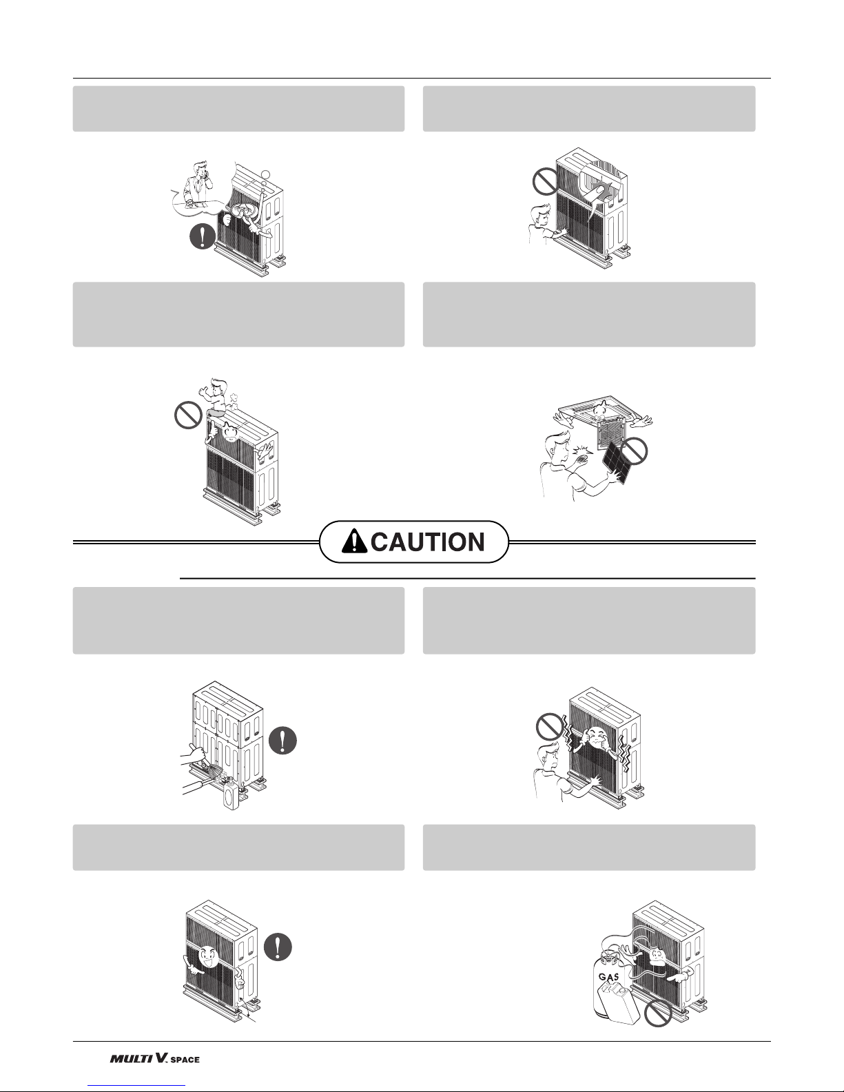
Turn on the power at least 2 hours before starting
operation.(In case of outdoor
temperature 5°C below)
•Starting operation immediately after turning on the
main power switch can result in severe
damage to internal parts. Keep the power switch
turned on during the operational season.
Donottouchanyoftherefrigerantpipingduring
and after operation.
•It can cause a burn or frostbite.
Do not operate the air conditioner with the panels
and guards removed.
•Rotating, hot, or high-voltage parts can cause injuries.
Do not directly turn off the main power switch after
stopping operation.
•Wait at least more than 5 minutes before turning off the
main power switch. Otherwise it may result in water
leakage or other problems.
Auto-addressing should be done in condition of
connecting the power of all indoor and outdoour
units. Auto-addressing should also be done in
case of changing the Indoor Unit board(PCB).
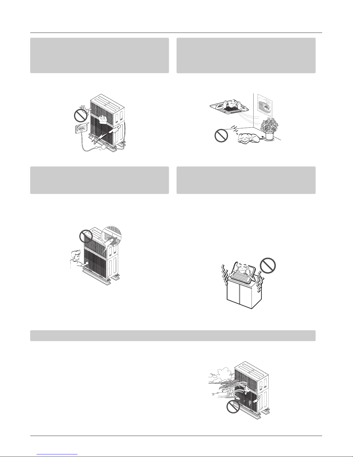
Useafirmstoolorladderwhencleaningormain-
taining the air conditioner.
•Be careful and avoid personal injury.
Do not insert hands or other objects through the
air inlet or outlet while the air conditioner is
plugged in.
•There are sharp and moving parts that could cause
personal injury.

10
Part 1
General Information
1. Model Names ................................................................11
1.1 Indoor Unit .............................................................11
1.2 Outdoor Unit ..........................................................11
2. External Appearance.....................................................12
2.1 Indoor Unit .............................................................12
2.2 Outdoor Unit ..........................................................13
3. Nomenclature.................................................................14
3.1 Indoor Unit .............................................................14
3.2 Outdoor Unit ..........................................................14
4. Outdoor Units information............................................15

Service Manual 11
1. Model Names
1.1 Indoor Unit
1.2 Outdoor Unit
Model Names
Power Supply 10HP Heat Pump
3Ø, 380 ~ 415V, 50Hz ARUN1008F20
Wall Mounted
SE ARNU07GSE*0 ARNU09GSE*0 ARNU12GSE*0
(General)
S5 ARNU18GS5*0 ARNU24GS5*0
Mirror
SE ARNU07GSE*0 ARNU09GSE*0 ARNU12GSE*0
S3 ARNU18GS3*0 ARNU24GS3*0
ART COOL
SP ARNU07GSP*0 ARNU09GSP*0 ARNU12GSP*0
ART COOL Wide
SV ARNU18GSV*0
1Way
TJ ARNU07GTJ*0 ARNU09GTJ*0 ARNU12GTJ*0
2Way
TL ARNU18GTL*0 ARNU24GTL*0
4Way
TE ARNU09GTE*0 ARNU12GTE*0 ARNU18GTE*0
TH ARNU24GTH*0 ARNU28GTH*0
TD ARNU36GTD*0 ARNU42GTD*0 ARNU48GTD*0
BH ARNU18GBHA0 ARNU24GBHA0
High Static
BG ARNU28GBGA0 ARNU36GBGA0 ARNU42GBGA0
BR ARNU48GBRA0
Low Static
B1 ARNU07GB1G0 ARNU09GB1G0 ARNU12GB1G0
B2 ARNU18GB2G0 ARNU24GB2G0
B1 ARNU07GB1G0 ARNU09GB1G0 ARNU12GB1G0
Built-in
PBSGB10 PBSGB10 PBSGB10
B2 ARNU18GB2G0 ARNU24GB2G0
PBSGB20 PBSGB20
VE ARNU09GVEA0 ARNU12GVEA0
Ceiling Suspended
VJ ARNU18GVJA0 ARNU24GVJA0
With Case
CE ARNU07GCEA0 ARNU09GCEA0 ARNU12GCEA0
CF ARNU18GCFA0 ARNU24GCFA0
Without Case
CE ARNU07GCEU0 ARNU09GCEU0 ARNU12GCEU0
CF ARNU18GCFU0 ARNU24GCFU0
Capacity(Btu/h(kW))
Category
Chassis
Name
7k 9k 12k 18k 24k 28k 36k 42k 48k
(2.2) (2.8) (3.6) (5.6) (7.1) (8.2) (10.6) (12.3) (14.1)
Ceiling
Concealed
Duct
Ceiling & Floor
Floor
Standing
Ceiling
Cassette
ART COOL
* ART COOL- Color, Ceiling Cassette- A:Basic C:Plasma, Wall Mounted- A:Basic L:Plasma

12
External Appearance
2. External Appearance
2.1 Indoor Units
Wall Mounted
ART COOL
ART COOL Wide
ART COOL Mirror
Ceiling Cassette- 1Way
Ceiling Cassette- 4Way
Ceiling & Floor
Ceiling Suspended
ARNU07GTJ*0
ARNU09GTJ*0
ARNU12GTJ*0
Ceiling Cassette -2Way
ARNU18GTL*0
ARNU24GTL*0
ARNU09GTE*0
ARNU12GTE*0
ARNU18GTE*0
ARNU24GTH*0
ARNU28GTH*0
ARNU36GTD*0
ARNU42GTD*0
ARNU48GTD*0
Ceiling Concealed Duct - Low Static
ARNU07GB1G0
ARNU09GB1G0
ARNU12GB1G0
ARNU18GB2G0
ARNU24GB2G0
ARNU07GSE*0
ARNU09GSE*0
ARNU12GSE*0
ARNU18GS5*0
ARNU24GS5*0
ARNU07GSE*0
ARNU09GSE*0
ARNU12GSE*0
ARNU18GS3*0
ARNU24GS3*0
ARNU07GSP*0
ARNU09GSP*0
ARNU12GSP*0
ARNU18GSV*0
Ceiling Concealed Duct-Built in
ARNU07GB1G0+PBSGB10(Acc'y)
ARNU09GB1G0+PBSGB10(Acc'y)
ARNU12GB1G0+PBSGB10(Acc'y)
ARNU18GB2G0+PBSGB20(Acc'y)
ARNU24GB2G0+PBSGB20(Acc'y)
ARNU09GVEA0
ARNU12GVEA0
ARNU18GVJA0
ARNU24GVJA0
Floor Standing
With case
ARNU07GCEA0
ARNU09GCEA0
ARNU12GCEA0
ARNU18GCFA0
ARNU24GCFA0
Without case
ARNU07GCEU0
ARNU09GCEU0
ARNU12GCEU0
ARNU18GCFU0
ARNU24GCFU0
Ceiling Concealed Duct - High Static
ARNU18GBHA0
ARNU24GBHA0
ARNU28GBGA0
ARNU36GBGA0
ARNU42GBGA0
ARNU48GBRA0
* A:Basic, L:Plasma
* A:Basic, C:Plasma
* A:Basic, C:Plasma * A:Basic, C:Plasma
S3:* B : Blue
M:Metal
D:Wood
R : Mirror
C : Cherry
W:White
SE:* R:Mirror
V:Silver
B:Blue
*B:Blue M:Metal
D:Wood W:White
These are model names of the basic function.
*B:Blue M:Metal
D : Wood W : White

Service Manual 13
External Appearance
2.2 Outdoor Units
ARUN1008F20
10HP

14
Nomenclature
3. Nomenclature
3.1 Indoor Unit
3.2 Outdoor Unit
ARN U G07 ATJ 0
Serial Number
Chassis Name
Electrical Ratings
1:1Ø, 115V, 60Hz 2: 1Ø, 220V, 60Hz
6:1Ø, 220 ~ 240V, 50Hz 7: 1Ø, 100V, 50/60Hz
G:1Ø, 220 ~ 240V, 50Hz / 220V 60Hz
Total Cooling Capacity in Btu/h unit
EX) 5,000 Btu/h➞'05' 18,000 Btu/h➞'18'
Combination of Inverter Type and
Cooling Only or Heat Pump
N: AC Inverter and H/P V: AC Inverter and C/O
U: DC Inverter and H/P and C/O
Indicates that this is System
Indoor Unit using the R410A
Combinations of functions
A:Basic function G:Low Static Motor
L:Nano Plasma(Wall Mounted)
C:Plasma(Ceiling Cassette) Q:Plasma(Low Static Duct)
ART COOL Type Panel Color
B:Blue D:Wood M:Metal R:Mirror W:White C:Cherry
ARU N 8100 F20
Chasiss Type
V : UV Chassis
1 : UV1 Chassis
2 : UV2 Chassis
Serial Number
Air Discharge DirectionS:Side Discharge
R : Right L :Left
F : Both
Electrical Ratings
8:3Ø, 380 ~ 415V, 50Hz 9: 3Ø, 380V, 60Hz
A: 3Ø, 220V, 50Hz B: 3Ø, 220V, 60Hz
Total Cooling Capacity in Horse Power(HP) unit
EX) 4.5HP➞'45' 10HP➞'100'
Combination of Inverter Type and
Cooling Only or Heat Pump
N: Inverter H/P V: Inverter C/O
B: Inverter and Heat Recovery
Indicates that this is System
Outdoor Unit using the R410A

Service Manual 15
4. Outdoor Units Information
Outdoor units Information
CAUTION: A ratio of the connectable Indoor Units with the Outdoor: Within 50 ~ 130%
A ratio of the running Indoor Units with the Outdoor: Within 10 ~ 100%
130% combination ratio cause a reduction of capacity.
Power Supply: Outdoor Unit (3Ø, 380 ~ 415V, 50Hz)
■Heat Pump
System(HP)
Model
Product Charge kg
CF(Correction Factor) kg
Max. Connectable No. of Indoor Units
Net Weight kg
lbs
Dimensions (W*H*D) mm
inch
Connecting Pipes Liquid Pipes[mm(inch)]
Gas Pipes[mm(inch)]
10
ARUN1008F20
9.5
0
16
350
771.6
1400*1790*650
55.1*70.5*25.6
Ø9.52(3/8)
Ø22.2(7/8)

16

Service Manual 17
Indoor Units

18 Indoor Unit

Service Manual 19
1. Specifications .............................................................................20
2. Functions ....................................................................................23
3. Operation Details........................................................................24
4. Dimensions .................................................................................26
5. Piping Diagrams .........................................................................28
6. Wiring Diagrams .........................................................................29
Ceiling Mounted Cassette Type (4Way)

20 Indoor Unit
1. Specification
Specification
Notes:-
1. Capacities are based on the following conditions:
Cooling •Indoor temp. 27°C[80.6°F]DB/ 19°C[66.2°F]WB
•Outdoor temp. 35°C[95°F]DB/ 24°C[75.2°F]WB
•Interconnecting Piping Length 7.5m
•Level Difference of Zero
Heating •Indoor temp. 20°C[68°F]DB/ 15°C[59°F]WB
•Outdoor temp. 7°C[44.6°F]DB/ 6°C[42.8°F]WB
•Interconnecting Piping Length 7.5m
•Level Difference of Zero
2. Capacities are net capacities
3. Due to our policy of innovation some specifications may be changed without notification
4. L.E.V.:Linear Expansion Valve
5. To be added for more available Models
Conversion Formula
kcal/h= kW x 860
Btu/h = kW x 3412
cfm = m3/min x 35.3
Type
Model Unit
W
Cooling Capacity kcal/h
Btu/h
W
Heating Capacity kcal/h
Btu/h
Casing
Body mm
Dimensions (W*D*H)
inch
Front Panel mm
inch
Coil
Rows x Columns x FPI
Face Area m2
Type
Motor Output x Number
W
Running Current A
Fan Air Flow Rate(H/M/L) cmm
cfm
Drive
Motor type
Temperature Control
Sound Absorbing Thermal Insulation Material
Safety Device
Liquid Side mm(inch)
Pipe Connections
Gas Side mm(inch)
Drain Pipe(Internal Dia.)
mm
Net Weight kg(lbs)
Noise Level
(Sound Press, 1.5m, H/M/L)
dBA±3
Power Supply Ø/V/Hz
Refrigerant Control
Power cable mm2
Transmission cable mm2
Panel Color
4 Way Ceiling Cassette
ARNU09GTEA0 ARNU12GTEA0 ARNU18GTEA0
2,800 3,600 5,600
2,400 3,100 4,800
9,600 12,300 19,100
3,200 4,000 6,300
2,800 3,400 5,400
10,900 13,600 21,500
Galvanized Steel Plate Galvanized Steel Plate Galvanized Steel Plate
570x570x269 570x570x269 570x570x269
22.4x22.4x10.5 22.4x22.4x10.5 22.4x22.4x10.5
670x670x30 670x670x30 670x670x30
26.4x26.4x1.2 26.4x26.4x1.2 26.4x26.4x1.2
2x11x18 2x11x18 2x11x18
0.32 0.32 0.32
Turbo Fan Turbo Fan Turbo Fan
35 35 35
0.18 0.18 0.18
9/8/7 11/10/9 13/12/10
318/282/247 389/353/318 459/424/353
Direct Direct Direct
BLDC BLDC BLDC
Microprocessor, Thermostat for cooling and heating Microprocessor, Thermostat for cooling and heating Microprocessor, Thermostat for cooling and heating
Foamed polystrene Foamed polystrene Foamed polystrene
Fuse, Thermal Fuse for Fan Motor Fuse, Thermal Fuse for Fan Motor Fuse, Thermal Fuse for Fan Motor
Ø6.35(1/4) Ø6.35(1/4) Ø6.35(1/4)
Ø12.7(1/2) Ø12.7(1/2) Ø12.7(1/2)
25.0 25.0 25.0
19(41.9) 19(41.9) 19(41.9)
39/33/30 41/35/32 43/37/35
1, 220 ~ 240, 50 1, 220 ~ 240, 50 1, 220 ~ 240, 50
1, 220, 60 1, 220, 60 1, 220, 60
LEV LEV LEV
CV2.0 X 3C CV2.0 X 3C CV2.0 X 3C
CVV-SB 1.25 X 2C CVV-SB 1.25 X 2C CVV-SB 1.25 X 2C
Morning fog Morning fog Morning fog
This manual suits for next models
3
Table of contents
Other LG Air Conditioner manuals
Popular Air Conditioner manuals by other brands

air choice
air choice TY-EA-03 user manual

Trane
Trane Packaged TerminalAir Conditioners & Heat... Installation operation & maintenance

Mitsubishi Electric
Mitsubishi Electric MFZ-KA25VA Service manual

Technibel
Technibel KPAFP165R5IA Series installation manual

Daikin
Daikin FFQ12LVJU Operation manual

Fujitsu
Fujitsu ASY7FSACW Service manual

Bard
Bard THE WALL-MOUNT WA3S3-A installation instructions

Frigidaire
Frigidaire GHWQ103WC1 use & care

Hitachi
Hitachi RAC-08CH8 installation manual

Toshiba
Toshiba TCB-SIR41U-E installation manual

Daikin
Daikin EWLD120MBYNN Installation instruction

Dometic
Dometic Blizzard NXT H540315 installation instructions