2Room Air Conditioner
Air Conditioner Service Manual
TABLE OF CONTENTS
LG Model Name ...............................................................................................................................................3
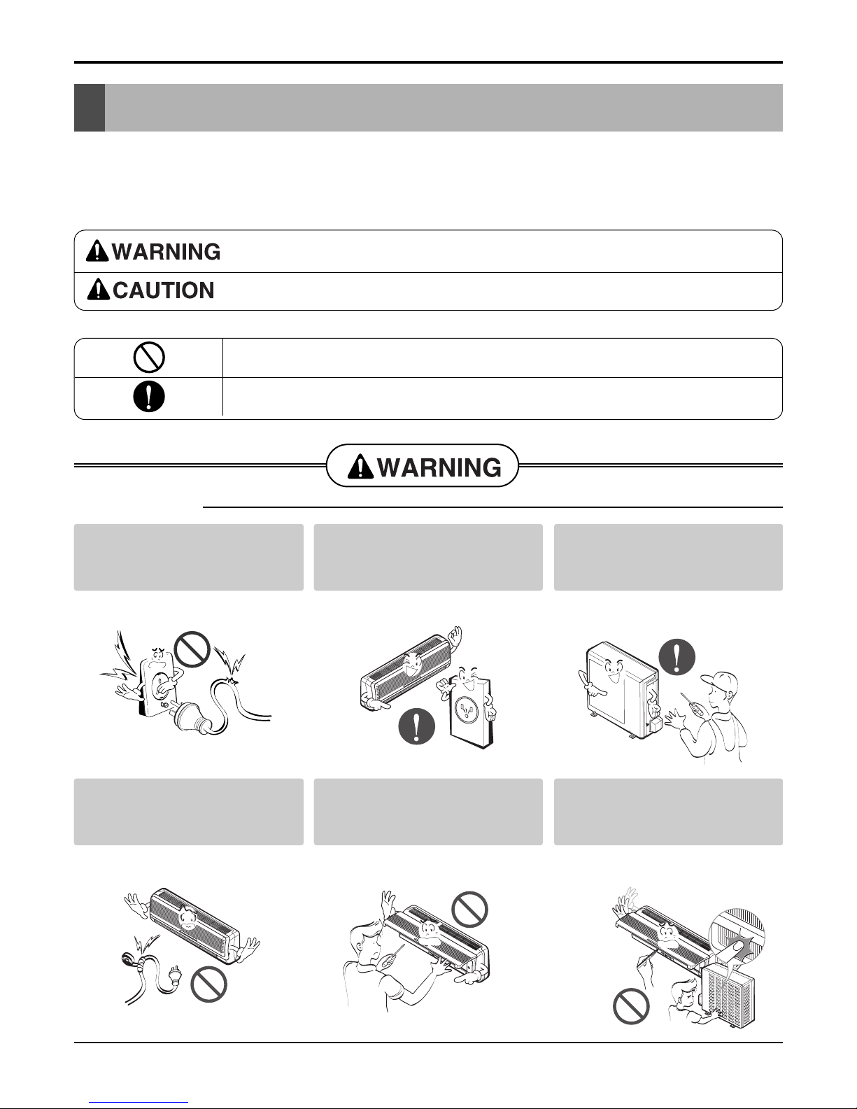
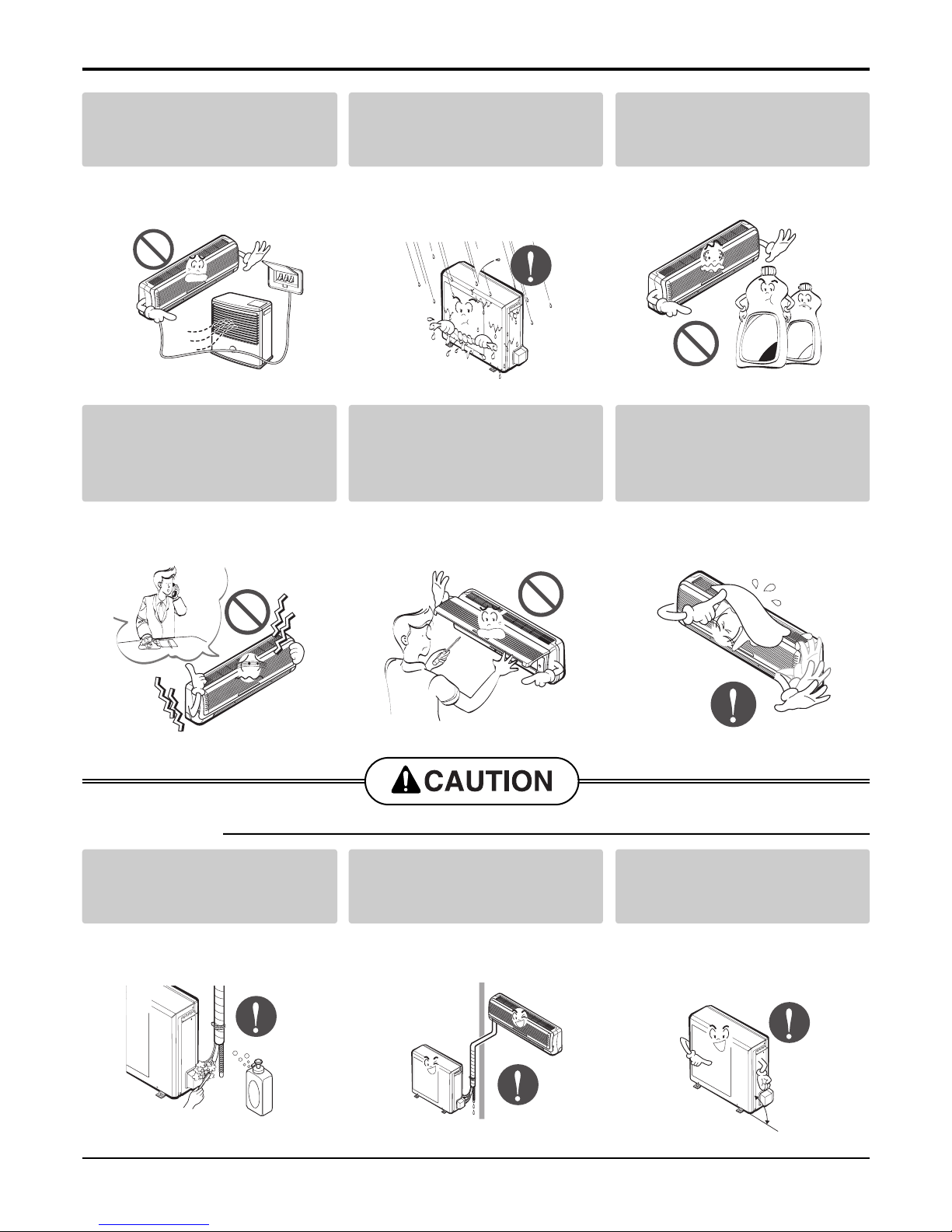
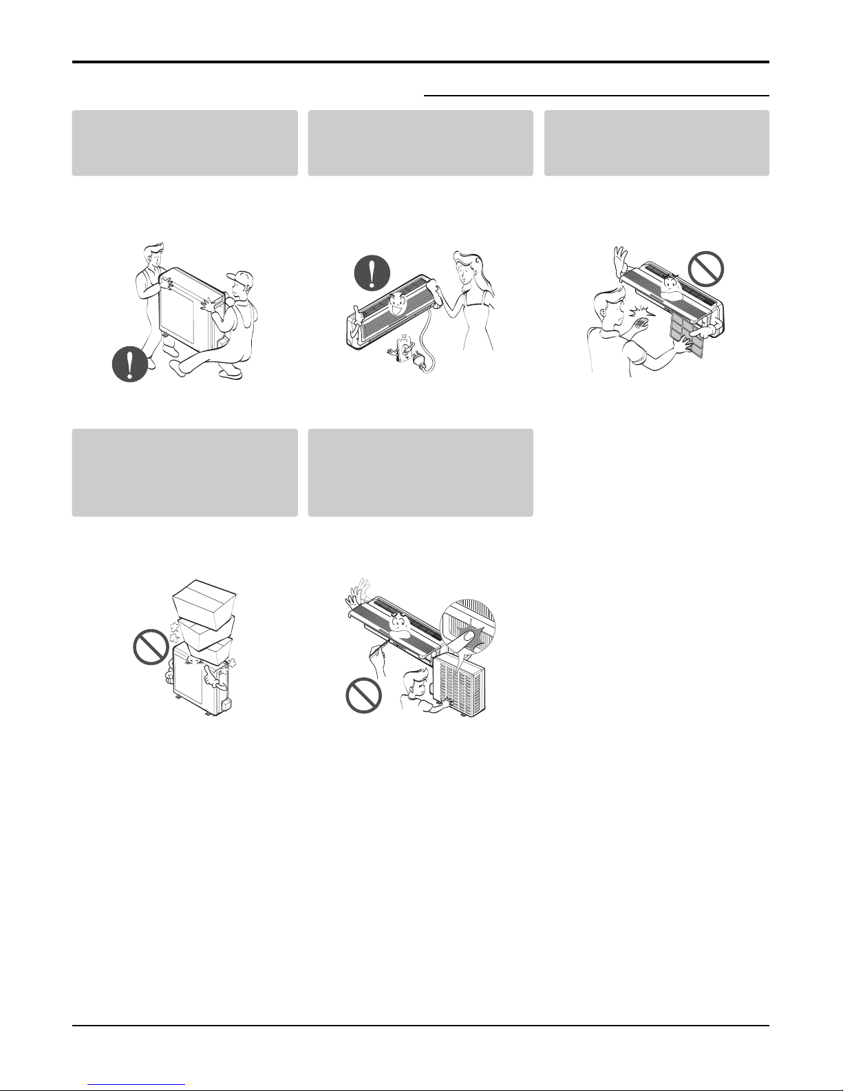
Safety Precautions..........................................................................................................................................4
Dimensions......................................................................................................................................................8
Symbols Used in this Manual.....................................................................................................................8
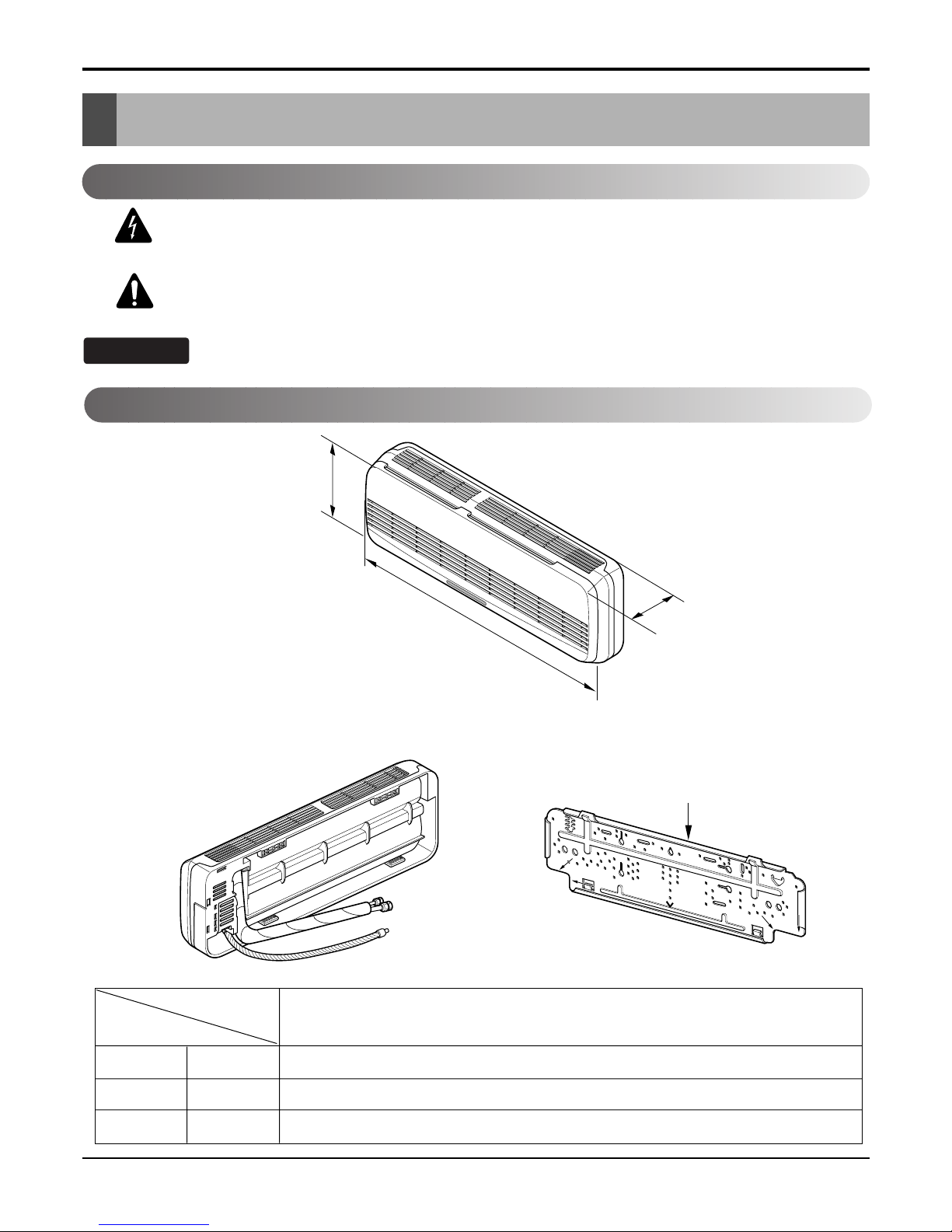
Indoor Unit..................................................................................................................................................8
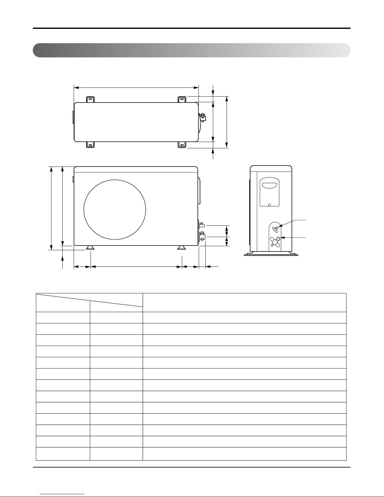
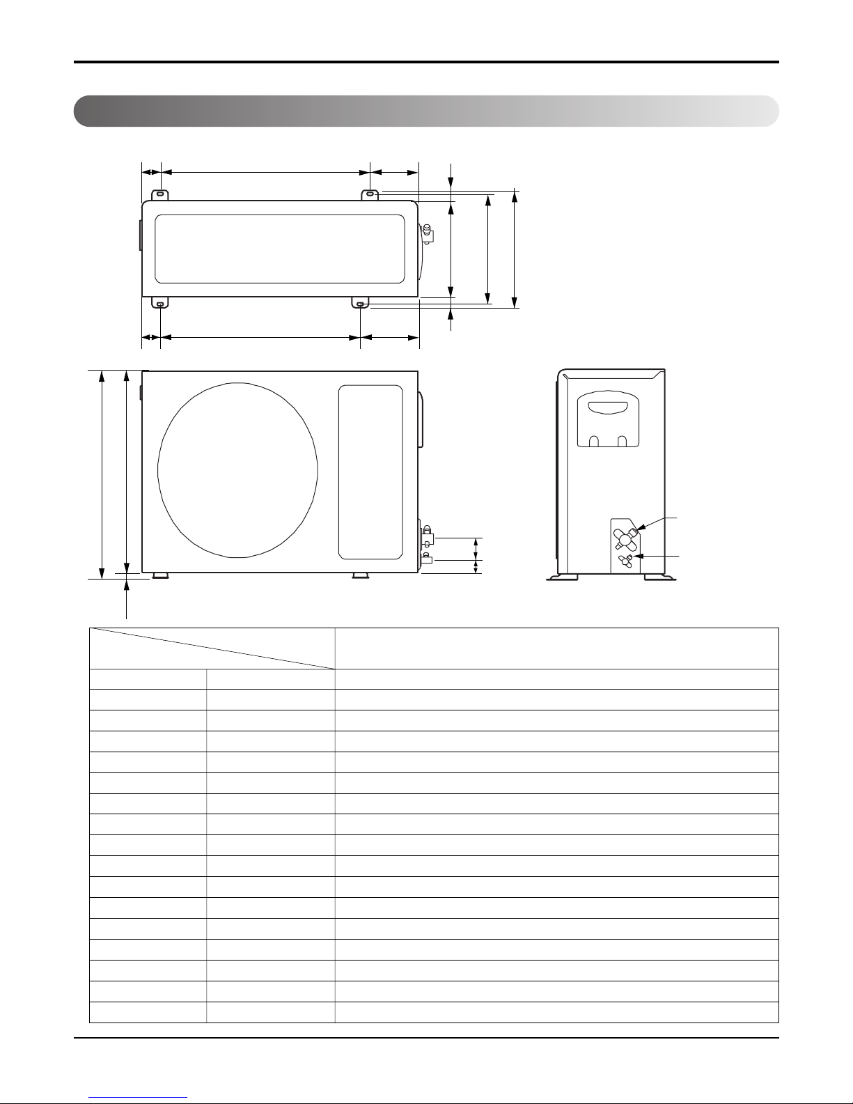
Outdoor Unit...............................................................................................................................................9
Product Specifications ................................................................................................................................12
Installation .....................................................................................................................................................13
Selection of the Best Location..................................................................................................................13
Piping Length and Elevation.....................................................................................................................13
How to Fix Installation Plate .....................................................................................................................14
Drill a Hole in the Wall ..............................................................................................................................14
Flaring Work.............................................................................................................................................15
Connection of Piping Indoor.....................................................................................................................16
Connection of the Pipes-Outdoor.............................................................................................................19
Connect the Cable to the Indoor Unit.......................................................................................................20
Connect the Cable to the Outdoor Unit ....................................................................................................21
Checking the Drainage.............................................................................................................................22
Form the Piping........................................................................................................................................22
Air Purging ...............................................................................................................................................23
Air Purging with Vacuum Pump................................................................................................................23
Main Unit Function ...................................................................................................................................26
Display Function ......................................................................................................................................33
Self-diagnosis Function............................................................................................................................33
Remote Control Operations......................................................................................................................34
Disassembly ..................................................................................................................................................36
Indoor Unit................................................................................................................................................36
Schematic Diagram.......................................................................................................................................39
Electric Control Device .............................................................................................................................39
Cooling Model ..........................................................................................................................................40
Heat Pump Model ....................................................................................................................................42
Wiring Diagram.........................................................................................................................................44
Components Location ..............................................................................................................................45
Troubleshooting Guide ................................................................................................................................47
Refrigeration Cycle Diagram ....................................................................................................................47
2-way, 3-way Valve .................................................................................................................................48
Cycle Parts...............................................................................................................................................55
Electronic Parts ........................................................................................................................................56
Exploded View ..............................................................................................................................................63
Replacement Parts List ................................................................................................................................66


 null")