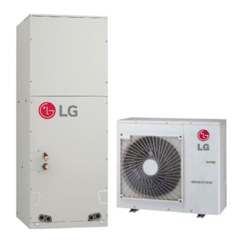
LG PAHCMS000 User manual

INSTALLATION MANUAL
FOR LG AIR HANDLER UNIT (AHU)
COMMUNICATIONS KIT
AHU Model Number: PAHCMS000

For continual product development, LG Electronics U.S.A., Inc. reserves the right to change specifications without notice.
© LG Electronics U.S.A., Inc.
PROPRIETARY DATA NOTICE
This document, as well as all reports, illustrations, data, information, and other materials are the property of
LG Electronics U.S.A., Inc., and are disclosed by LG Electronics U.S.A., Inc. only in confidence.
For more materials such as submittals, catalogs, engineering,
installation, owner’s, and service manuals, visit www.lghvac.com.
Do not throw away, destroy, or lose this manual.
Please read carefully and store in a safe place for future reference.
Content familiarity required for proper installation.
The instructions included in this manual must be followed to prevent product malfunction, property damage, injury, or death to the user or
other people. Incorrect operation due to ignoring any instructions will cause harm or damage. The level of seriousness is classified by the
symbols described by the summary list of safety precautions on page 3.

3
Due to our policy of continuous product innovation, some specications may change without notication.
©LG Electronics U.S.A., Inc., Englewood Cliffs, NJ. All rights reserved. “LG” is a registered trademark of LG Corp.
TABLE OF CONTENTS
Safety Precautions ..........................................................................................................................................................................4
AHU Kit Introduction.......................................................................................................................................................................7
Specications, Components List...................................................................................................................................................8
AHU Communications Kit Installation...........................................................................................................................................9
Selecting the Best Location�����������������������������������������������������������������������������������������������������������������������������������������������������������9
DIP Switch Settings ���������������������������������������������������������������������������������������������������������������������������������������������������������������������10
AHU Communications Kit Parts ��������������������������������������������������������������������������������������������������������������������������������������������������13
AHU Communications Kit Mounting �������������������������������������������������������������������������������������������������������������������������������������������14
Power Wiring ������������������������������������������������������������������������������������������������������������������������������������������������������������������������������18
Communications Wiring���������������������������������������������������������������������������������������������������������������������������������������������������������������19
Controller Settings�����������������������������������������������������������������������������������������������������������������������������������������������������������������������20
Solutions Overview����������������������������������������������������������������������������������������������������������������������������������������������������������������������24
Main Module Settings������������������������������������������������������������������������������������������������������������������������������������������������������������������27
Communication Module���������������������������������������������������������������������������������������������������������������������������������������������������������������31
Defrost Setting�����������������������������������������������������������������������������������������������������������������������������������������������������������������������������32
External Connection Diagrams����������������������������������������������������������������������������������������������������������������������������������������������������33
Discharge Air Temperature Controller������������������������������������������������������������������������������������������������������������������������������������������37
EEV Kit Installation........................................................................................................................................................................45
Introduction, Specications, and Design Parameters������������������������������������������������������������������������������������������������������������������45
EEV Kit Parts������������������������������������������������������������������������������������������������������������������������������������������������������������������������������46
Mounting the EEV Kit ������������������������������������������������������������������������������������������������������������������������������������������������������������������48
Preparing the Pipes���������������������������������������������������������������������������������������������������������������������������������������������������������������������49
Brazing and Insulating the Piping������������������������������������������������������������������������������������������������������������������������������������������������50
PRLK048A0 and PRLK096A0 Wiring������������������������������������������������������������������������������������������������������������������������������������������51
PRLK396A0 Wiring����������������������������������������������������������������������������������������������������������������������������������������������������������������������52
Control Functions ������������������������������������������������������������������������������������������������������������������������������������������������������������������������53
Testing ............................................................................................................................................................................................57
Troubleshooting ............................................................................................................................................................................58

4
PRDCAM AHU Communication Kit Installation Manual
Due to our policy of continuous product innovation, some specications may change without notication.
©LG Electronics U.S.A., Inc., Englewood Cliffs, NJ. All rights reserved. “LG” is a registered trademark of LG Corp.
TABLE OF SYMBOLS
This symbol indicates an imminently hazardous situation which, if not avoided, will result in death or serious injury�
This symbol indicates a potentially hazardous situation which, if not avoided, could result in death or serious injury�
This symbol indicates a potentially hazardous situation which, if not avoided, may result in minor or moderate injury�
This symbol indicates situations that may result in equipment or property damage accidents only�
This symbol indicates an action should not be completed�
DANGER
CAUTION
The instructions below must be followed to prevent product malfunction, property damage, injury or death to the user or other people. Incor-
rect operation due to ignoring any instructions will cause harm or damage. The level of seriousness is classified by the symbols described
below.
Installation
All electrical work must be performed by a licensed electri-
cian and conform to local building codes or, in the absence
of local codes, with the National Electrical Code, and the
instructions given in this manual.
If the power source capacity is inadequate or the electric work is not
performed properly, it may result in re, electric shock, physical injury or
death�
Do not touch the communications and EEV kits’ wir-
ing, terminals, or other electrical components with tools or
exposed skin when the power is connected. Only qualied
technicians should install, remove, or re-install the kits.
Improper installation or use may result in re, electric shock, physical
injury or death�
Do not install, remove, or re-install the communications
and EEV kits by yourself (end user). Ask the dealer or a qual-
ied technician familiar with safety procedures and equipped
with the proper tools and test instruments to install the kits.
Improper installation by the user may result in re, electric shock, physi-
cal injury or death�
For replacement of an installed communications and EEV
kits, always contact a qualied LG service provider familiar
with safety procedures and equipped with the proper tools
and test instruments.
There is risk of re, electric shock, and physical injury or death.
Do not install the communications and EEV kits in a loca-
tion where the kits can be exposed to rain, snow, etc.
There is risk of physical injury or death due to electric shock�
Safely dispose of the packing materials.
Tear apart and throw away plastic packaging bags so that children may
not play with them and risk suffocation and death�
Wear protective gloves when unpacking, installing, and han-
dling the kits. Sharp edges may cause personal injury.
Do not install the communications and EEV kits in loca-
tions where either kit could fall down.
There is risk of physical injury�
Use the appropriate parts and connectors.
There is risk of physical injury or death due to re and / or electric shock.
Replace all control box and panel covers on the communica-
tions and EEV kits.
If cover panels are not installed securely, dust, water, and animals may
enter the kits, causing re, electric shock, and physical injury or death.
Failure to carefully read and follow all instructions in this
manual can result in physical injury or death.
Only qualied technicians familiar with safety procedures
and equipped with the proper tools and test instruments
should install, remove, or re-install the communications and
EEV kits.
Improper installation or use may result in product malfunction�
Do not install the communications and EEV kits in a
location where the kits can be exposed to rain, snow, etc.
There is risk of product malfunction�
Do not drop the communications and EEV kits.
It may damage the products�
Failure to carefully read and follow all instructions in this
manual can result in property damage and equipment mal-
function.
SAFETY PRECAUTIONS

5
Safety Precautions
Due to our policy of continuous product innovation, some specications may change without notication.
©LG Electronics U.S.A., Inc., Englewood Cliffs, NJ. All rights reserved. “LG” is a registered trademark of LG Corp.
SAFETY PRECAUTIONS
Do not supply power to the communication and EEV kits
until all electrical wiring, controls wiring, piping, installation,
and refrigerant evacuation are completed for the whole air
conditioning system.
The information contained in this manual is intended for use
by an industry-qualied, experienced, certied electrician
familiar with the U.S. National Electric Code (NEC) who is
equipped with the proper tools and test instruments.
Failure to carefully read and follow all instructions in this manual can
result in equipment malfunction or property damage�
The information contained in this manual is intended for use
by an industry-qualied, experienced, certied electrician
familiar with the U.S. National Electric Code (NEC) who is
equipped with the proper tools and test instruments.
Failure to carefully read and follow all instructions in this manual can
result in personal injury or death�
All electric work must be performed by a licensed electrician
and conform to local building codes or, in the absence of
local codes, with the National Electrical Code, and the
instructions given in this manual.
If the power source capacity is inadequate or the electric work is not
performed properly, it may result in re, electric shock, physical injury or
death�
Refer to local, state, and federal codes, and use power wires
of sucient current capacity and rating.
Wires that are too small may generate heat and cause a re and physi-
cal injury or death�
Secure all eld wiring connections with appropriate wire
strain relief.
Improperly securing wires will create undue stress on equipment power
lugs. Inadequate connections may generate heat, cause a re and
physical injury or death�
Verify that all power wiring, plugs, and sockets are not loose
or damaged.
Loose wiring may overheat at connection points, causing a re, electrical
shock, physical injury or death�
WIRING
DANGER
High voltage electricity is required to operate the commu-
nications and EEV kits. Adhere to the NEC code and these
instructions when wiring.
Improper connections and inadequate grounding can cause accidental
injury or death�
Always ground the communications and EEV kits following
local, state, and NEC codes.
There is risk of re, electric shock, and physical injury or death.
Turn the power o at the nearest disconnect before servicing
the equipment.
Electrical shock can cause physical injury or death�
Properly size all circuit breakers or fuses.
There is risk of re, electric shock, explosion, physical injury or death.
Communication kit requires its own power source (EEV kit
is powered o of Communication kit). Do not share the
power source with other equipment.
There is risk of heat generation which may cause re, electric shock,
explosion, physical injury or death�

6
PRDCAM AHU Communication Kit Installation Manual
Due to our policy of continuous product innovation, some specications may change without notication.
©LG Electronics U.S.A., Inc., Englewood Cliffs, NJ. All rights reserved. “LG” is a registered trademark of LG Corp.
Do not install the communications and EEV kits in loca-
tions exposed to open ame or extreme heat. Do not touch
the kits with wet hands.
There is risk of re, electric shock, physical injury or death.
Do not modify or extend the power supply cords.
There is risk of re, electric shock, physical injury or death.
Do not step or place anything on the communications
and EEV kits.
If the product falls, there is risk of physical injury�
Do not place heavy objects on the communications and
EEV kits’ power cables.
There is risk of re, electric shock, physical injury or death.
Only authorized persons should operate the communications
and EEV kits.
If the kits are not operated properly, there is a risk of physical injury�
Do not provide power to or operate communication and
EEV kits if the kits are ooded or submerged. Always have
the dealer or an authorized technician to service the kits.
There is risk of re, electric shock, physical injury or death.
Do not store or use ammable gas or combustibles near
the communications and EEV kits.
There is risk of re, explosion, and physical injury or death.
Unplug the communication and EEV kits if either kit emits
strange sounds, smells, or smoke.
There is risk of re, electric shock, physical injury or death.
Do not let the communication and EEV kits get wet.
There is risk of product failure or malfunction�
Only authorized persons should operate the communication
and EEV kits.
There is risk of product failure or malfunction�
Do not drop the communications and EEV kits.
There is risk of product failure or malfunction�
Do not step or place anything on the communications
and EEV kits.
If the product falls, there is risk of product damage�
OPERATION
DANGER
CAUTION
SAFETY PRECAUTIONS

7
General Specifications
Due to our policy of continuous product innovation, some specications may change without notication.
©LG Electronics U.S.A., Inc., Englewood Cliffs, NJ. All rights reserved. “LG” is a registered trademark of LG Corp.
AHU KIT INTRODUCTION
Figure 1: PAHCMS000 AHU
Communications Kit.
Figure 2: AHU Communications Kit System Schematic.
Introduction
The PAHCMS000 AHU Communications Kit bridges LG’s air conditioning outdoor unit to a third party Air
Handling Unit (AHU). Its function is based on discharge or supply air temperature control. In installations
where the AHU is designed with Direct Expansion (DX) Coil, the PAHCMS000 will control the supply air
temperature by measuring the inlet and outlet temperatures of the DX coil and changd the operation of
the outdoor unit and the expansion unit. PAHCMS000 AHU Communications Kit features are:
• It can be used with LG Multi V air or water source outdoor units and LG Single Zone outdoor units.
• It supports AHU coil capacities from 12 - 594 kBtu/h.
• It controls the Electronic Expansion Valve (EEV, required, sold separately)
• It measures the supply air temperature through the enclosed temperature sensor and controls the
outdoor unit to secure the demanded supply air temperature.
• It can be directly connected to direct digital control (DDC) without a separate control module, so DDC
can receive product control and status information through Modbus communication.
• The PAHCMS000 AHU Communications Kit consists of a chassis, communication module, pipe-in
thermistor, pipe-out thermistor, and return air thermistor.
• Supply air temperature control is possible without DDC.
• It increases heating comfort by applying sequential defrost logic and simultaneous defrosting preven-
tion logic of the outdoor unit.
Control Signal (field supplied)
Pipe
Thermistor Signal
Refrigerant flow (cooling)
Refrigerant flow (heating)
LG Wired
Controller2
Third-Party
AHU
Controller1
Air flow
LG AHU
EEV Kit
Third-Party
Air Handling
Unit
LG Multi V
Air Source or
Water Source Unit4
1Third-party AHU controller is recommended.
2LG wired controller (required accessory) functions as error code display only.
No system control available.
3Return air temperature thermistor can be replaced with fixed resistor when AHU
controller is using third-party temperature sensors.
4Compatible units are Multi V and Single Zone.
Return Air
Thermistor3
Max
Length
32 feet
LG AHU
Comm Kit
PAHCMS000
Vapor
Piping
Liquid
Piping
Pipe Out
Sensor (Vapor)
Pipe In
Sensor
(Liquid)

8
PRDCAM AHU Communication Kit Installation Manual
Due to our policy of continuous product innovation, some specications may change without notication.
©LG Electronics U.S.A., Inc., Englewood Cliffs, NJ. All rights reserved. “LG” is a registered trademark of LG Corp.
Specifications
Table 1: PAHCMS000 AHU Communications Kit Specications Table.
AHU Communications Kit Components
Table 2: PAHCMS000 AHU Communications Kit Components Table (factory supplied).
Kit Model Number PAHCMS000
For Use With Multi V and Single Zone
Power Supply Requirements 208-230VAC, 60Hz, 1Ph
Rated Current 0.1A
Ambient Operating Temperature Range -4 to +149°F
Ambient Operating Humidity Range 0 to 98% (Non-condensing)
Dimensions (in., W x H x D) 14-31/32” W x 6-3/32” H x 11-13/16” D
Net Weight (lbs.) 16.5
Shipping Weight (lbs.) 19.4
Communications RS-485 (4 wires required: 2 connect to IDU A/B terminals and 2 connect to UI4/G terminals on ODU)
Communications Cable AWG 18 x 4 Stranded, Shielded Copper Cable
Part Quantity Image
AHU
Communications Kit One (1)
Return Air (Room)
Thermistor One (1)
Pipe Thermistor
Two (2)
(One [1] Pipe In,
One [1] Pipe Out)
AHU COMMUNICATIONS KIT SPECIFICATIONS,
COMPONENTS LIST

9
Installation
Due to our policy of continuous product innovation, some specications may change without notication.
©LG Electronics U.S.A., Inc., Englewood Cliffs, NJ. All rights reserved. “LG” is a registered trademark of LG Corp.
AHU Communications Kit Design Parameters
• Minimum coil entering air temperature is 41°F when system is operating in heating mode.
• AHU coil sizing parameters:
• Suction (evaporating) temperature for coil sizing is 41°F, Condensing (liquid) temperature for coil sizing is 110°F.
• Recommended coil tube sizes: 3/8 or 1/2 inches.
• Coil volume is needed to calculate additional refrigerant charge amount.
• Coils larger than 16 tons should be divided into multiple circuits to allow EEV Kit connection kit (EEV Kit sold separately).
• Pipe sizing rules are same rules as the connected air-source or water-source heat pump (see respective Engineering and Installation
Manuals for more information).
• Maximum recommended combination ratio is 100%.
• AHU Communications Kits and EEV Kits (sold separately) are not weatherproof and must be protected from rain, snow, etc.
AHU COMMUNICATIONS KIT INSTALLATION
Selecting the Best Location
AHU Operation Range
Range of the heat exchanger inlet air temperature is 64.4 to 104°F for cooling, and 41 to 86°F for heating. If the temperature is <64.4°F
for cooling and >86°F for heating, the system might cycle on and off because of the system’s protection logic.
Application Condition
100% outside air intake: The AHU(s) is (are) the only indoor unit(s)
connected to the air-source / water-source heat pump unit(s).
The total capacity of 100% outside air intake AHU(s) should be
50~100% of the air-source / water-source heat pump.
To measure room temperature accurately, install the room thermistor in the heat exchanger inlet� If the room thermistor is not installed
properly, the AHU may not operate properly. Room thermistor can be replaced with xed resistor when using a third-party AHU controller.
Table 3: AHU Application and Condition.
Selecting the Best Location
Do
• Install the AHU Communications and EEV Kits with the access panels facing outward.
• Install in a location that can support the weight of the kits.
• Install the EEV kit on the AHU as close as possible to the heat exchanger.
Don’t
• Don’t install or operate the unit in an area where mineral oils, sulphuric gases, acidic or alkaline vapors or spray are present.
• Don’t install in an area where the air contains high levels of salt (oceanside locations).
• Don’t install in vehicles or vessels.
• Don’t install in an area where voltage fluctuates significantly (factories), or near machines that generate electromagnetic waves.

10
PRDCAM AHU Communication Kit Installation Manual
Due to our policy of continuous product innovation, some specications may change without notication.
©LG Electronics U.S.A., Inc., Englewood Cliffs, NJ. All rights reserved. “LG” is a registered trademark of LG Corp.
Communication Module
Main Module
The default setting of all DIP switches is “off”
etoNgnitteSmetIoNemanW/S
SW1
1 Control Type
On Communication Controlled by DDC through Modbus or LG centralized controller
Off Contact signal Controlled by DDC through Contact signal AI and DI
LG Centralized controller can only monitor status
2Discharge Temp.
Control Type
On Stand alone Discharge temp. control by LG controller using own discharge
temp. sensor
Off Manual by DDC Discharge temp. control by DDC using filed supplied discharge
temp. sensor
3Defrost Operation
Type¹
On Normal In case of multiple outdoor units, Defrost operation can be oper-
ated simultaneously
Off Sequential
Start up
In case of multiple outdoor units, the outdoor unit is sequentially
started at intervals of 10 minutes
4
Central
Communication
Type
On LG Central Comm Modbus Communication
Off - Not Used
SW2
1ODU Capacity
Control
On ODU Capacity
Setting #2 ODU capacity control #2
Off ODU Capacity
Setting #1 ODU capacity control #1
---devreseR2
---devreseR3
---devreseR4
SW3
---devreseR1
---devreseR2
---devreseR3
---devreseR4
SW4
---devreseR1
---devreseR2
---devreseR3
---devreseR4
Note:
1. Function of defrost operation type can be applied only to Multi V outdoor units (after MULTI V 5 model).
Figure 3: Main Module DIP Switches.
Table 4: Main Module DIP Switch Settings
AHU COMMUNICATIONS KIT INSTALLATION
DIP Switch Settings

11
Installation
Due to our policy of continuous product innovation, some specications may change without notication.
©LG Electronics U.S.A., Inc., Englewood Cliffs, NJ. All rights reserved. “LG” is a registered trademark of LG Corp.
AHU COMMUNICATIONS KIT INSTALLATION
DIP Switch Settings
Communication Module
Main Module
The default setting of all dip switch is set “off”
Note :
1. Do not change the settings of reserved switches. Changing these settings can result in equipment malfunction.
etoNgnitteSmetIoNemanW/S
SW1
1 ODU Type On Single Comm Using Single Split outdoor unit
Off MULTI V Comm Using MULTI V outdoor unit
2 Control Type On Communication Controlled by Modbus between modules
Off Contact signal Not used
3 DO Type On Fan Speed Not used
Off Status Not used
4Fan Speed
(TH. On/Off)
On Fixed Not used
Off Change Not used
SW2
---devreseR1
---devreseR2
3/4 UI Setting
Off/Off UI Setting #1 Not used
Off/On UI Setting #2 Not used
--ffO/nO
--nO/nO
SW3
1 Master/Slave On Slave mode Not used
Off Master mode Master is default
2/3 Operation mode
setting
Off/Off Heat Pump Cooling or Heating operation mode is available
Off/On Heating Only Operation mode is Heating only (Heating / Ventilation)
On/Off Cooling Only Operation mode is Cooling only (Cooling / Ventilation )
-devreseRnO/nO
---devreseR4
SW4 1~4 Capacity Index
Setting - - According to ODU Type, you can setup the capacity index of
MULTI V or Single Split
Figure 4: Communications Module DIP Switches.
Table 5: Communications Module DIP Switch Settings

12
PRDCAM AHU Communication Kit Installation Manual
Due to our policy of continuous product innovation, some specications may change without notication.
©LG Electronics U.S.A., Inc., Englewood Cliffs, NJ. All rights reserved. “LG” is a registered trademark of LG Corp.
AHU COMMUNICATIONS KIT INSTALLATION
DIP Switch Settings
Table 6: SW4 DIP Switch Settings for AHU Capacity
SW4 DIP switches
Capacity (kBTU/h)
MULTI V
5211
7512
9813
21424
51825
81636
42247
03848
63459
246701
846911
0651121
0743131
5835141
devreseR27151
devreseR29161
Single Zone
Switch
Number
Notes:
1. PAHCMS000 AHU can be connected to the PRLK048A0, PRLK096A0, or PRLK396A0 EEV kits only.
2. If connecting the PRLK396A0 EEV kit to a Multi V outdoor unit, set DIP switches 1, 2, 3, and 4 to ON
to set capacity to 192 kBtu/h.

13
Installation
Due to our policy of continuous product innovation, some specications may change without notication.
©LG Electronics U.S.A., Inc., Englewood Cliffs, NJ. All rights reserved. “LG” is a registered trademark of LG Corp.
1
2
4
6
3
5
AHU COMMUNICATIONS KIT INSTALLATION
AHU Communications Kit Parts
Figure 5: AHU Communications Kit Parts Diagram.
Table 7: AHU Communications Kit Parts Table.
Diagram Label Part Name Quantity
1Thermistor Assembly, NTC Three (3)
2 Harness, Multi One (1)
3 Main Module One (1)
4 Communications Module One (1)
5 Bracket One (1)
6Panel Assembly, Control Three (3)

14
PRDCAM AHU Communication Kit Installation Manual
Due to our policy of continuous product innovation, some specications may change without notication.
©LG Electronics U.S.A., Inc., Englewood Cliffs, NJ. All rights reserved. “LG” is a registered trademark of LG Corp.
1. Use the key to open the AHU Communication Kit door.
2. Remove the four nuts from the four captive bolts at the corners of the control panel assembly.
3. Carefully remove the control panel assembly from the AHU Communication Kit.
4. Use the AHU Communication Kit as a template and mark the locations of the screw holes on the mounting surface.
NOTE: Do not drill holes without removing the control panel assembly.
Metal shavings can collect on the control panel assembly and damage the equipment when power is applied�
5. Drill the four holes for the field-supplied screws. Ensure the drill bit does not damage any equipment or components.
6. Carefully replace the control panel assembly and secure with the four nuts on the four captive bolts.
7. Position the AHU Communications Kit at the mounting location and secure with four field-supplied screws. Ensure the screws
do not damage any equipment or components.
Figure 6: AHU Communications Kit Installation
AHU COMMUNICATIONS KIT INSTALLATION
AHU Communications Kit Mounting
Model
PAHCMS000 14 31/32 6-3/32 11-13/16 13-2/5 10-1/4
11/32 Holes (4)
BackFrontSide
Size (inch)
W D H A B
D W A
B
H

15
Installation
Due to our policy of continuous product innovation, some specications may change without notication.
©LG Electronics U.S.A., Inc., Englewood Cliffs, NJ. All rights reserved. “LG” is a registered trademark of LG Corp.
AHU COMMUNICATIONS KIT INSTALLATION
Wiring Diagram
Figure 7: AHU Communications Kit Wiring Diagram
Thermistor
Return

16
PRDCAM AHU Communication Kit Installation Manual
Due to our policy of continuous product innovation, some specications may change without notication.
©LG Electronics U.S.A., Inc., Englewood Cliffs, NJ. All rights reserved. “LG” is a registered trademark of LG Corp.
AHU COMMUNICATIONS KIT INSTALLATION
Wiring Diagram
*DI is available when Dip SW1-1 is Off
Name Port Value Electrical Spec Function
Short Open
On/Off DI1 On Off Non voltage Operation On/Off
Cool/Heat DI2 Heating Cooling Non voltage Operation Mode
Emer. Stop DI3 Emergency Stop Normal Non voltage Emergency Stop Input (Priority operation)
noitcnuF.cepSlacirtcelEeulaVtroPemaN
Alarm DO1 30 VDC / 5 A
250 VAC / 5 A
Output normal or error status (Relay C Contact)
- A Contact
Normal status : open
Error status : short
- B Contact
Normal status : short
Error status : open
-Normal Status
A B COM
-Error Status
A B COM
noitcnuF.cepSlacirtcelEmetItroPemaN
ODU Comm. RS485 CH2
ODU Comm.
(CEN A/B or
INT A/B)
Max 3280 ft,
2C x 18~16 AWG
(shield wire)
Communication with MULTI V/Single
split ODU for ODU Capacity control
LG
Central Comm. RS485 CH3 LG Central Comm.
Max 1640 ft,
2C x 18~16 AWG
(shield wire)
Communication with LG centralized
controller through LGAP Protocol
DDC Central
Comm. RS485 CH4 DDC(Modbus)
Central Comm.
Max 1640 ft,
2C x 18~16 AWG
(shield wire)
Communication with DDC central-
ized controller through Modbus pro-
tocol
Table 8: RS485 Communication Port
Table 9: Digital Input
Table 10: Digital Output – Relay C Contact

17
Installation
Due to our policy of continuous product innovation, some specications may change without notication.
©LG Electronics U.S.A., Inc., Englewood Cliffs, NJ. All rights reserved. “LG” is a registered trademark of LG Corp.
AHU COMMUNICATIONS KIT INSTALLATION
Wiring Diagram
Name Port Value noitcnuF.cepSlacirtcelE
Short Open
On/Off DO2 On Off
12 VDC / 1 A,
250 VAC / 3 A
Operation On/Off status
sutatstsorfeDUDOlamroNtsorfeD3ODtsorfeD
sutatsffO/nOnoitareporosserpmoCffOnO4ODsutatS.pmoC
---5ODdevreseR
---6ODdevreseR
noitcnuF.cepSlacirtcelEeulaVtroPemaN
---1IUdevreseR
---2IUdevreseR
---3IUdevreseR
---4IUdevreseR
---5IUdevreseR
---6IUdevreseR
Capacity Control¹
0~10V
UI7
(AI) 0~10 V Input DC 0~10 V,
20 mA
ODU Capacity control input(0~10 V)
*When Temp. Control Type is ‘Manual by
DDC’(SW 1-2 : Off), refer to UI7 Analog Input
---8IUdevreseR
1. Refer to the Capacity Control (UI7) combination ratio table.
2. UI is available when Dip SW1-1 is Off
Table 11: Digital Output
Table 12: Universal Input

18
PRDCAM AHU Communication Kit Installation Manual
Due to our policy of continuous product innovation, some specications may change without notication.
©LG Electronics U.S.A., Inc., Englewood Cliffs, NJ. All rights reserved. “LG” is a registered trademark of LG Corp.
Power Wiring
AHU COMMUNICATIONS KIT INSTALLATION
Figure 8: Power Wiring Connection.
General Power Wiring Guidelines
All electrical work must be performed by a licensed electrician and conform to local building codes or, in the absence of
local codes, with the National Electrical Code, and the instructions in this manual.
Inadequate power source capacity or improper electric work may result in re, electric shock, physical injury or death.
All eld-supplied parts, materials, and electric work must be conform to local codes.
Improper components and installation may result in re, electric shock, physical injury or death.
A main switch or disconnect, in accordance with relevant local and national codes, and having a contact separation in
all poles, must be incorporated in the wiring.
Improper installation by the user may result in re, electric shock, physical injury or death.
Refer to the air-source / water-source heat pump unit installation manual for power wiring sizes, circuit breaker and
switch capacities, and wiring instructions.
If the power source capacity for the air-source unit / water-source unit is inadequate or the electric work is not performed properly, it may result
in re, electric shock, physical injury or death.
Use copper wire only and connect wires tightly to the terminals. Install wiring so that other equipment is not obstructed.
Improper or incomplete connections could result in overheating, re, electric shock, physical injury or death.
Ensure the power source is disconnected before performing this procedure.
If the power source is connected during this procedure, it could result in electric shock, physical injury, or death�
1. Carefully pull the power cable through the cable nut and grommet.
2. Connect the power cable to the power terminal block.
3. Pull enough cable through the nut and grommet to allow enough slack for strain relief.
4. Tighten the cable nut.
Front View with Cover Open
Power Terminal Block
Cable
Insert

19
Installation
Due to our policy of continuous product innovation, some specications may change without notication.
©LG Electronics U.S.A., Inc., Englewood Cliffs, NJ. All rights reserved. “LG” is a registered trademark of LG Corp.
AHU COMMUNICATIONS KIT INSTALLATION
Communications Wiring
• Communications wiring must be 18 gauge, shielded, and stranded�
• The thermistor cable, remote controller wires, and communications wires should be positioned at least two (2) inches away from pow-
er supply wires� If these wires are installed too closed together, it may result in product malfunction due to electrical interference�
All electrical work must be performed by a licensed electrician and conform to local building codes or, in the absence
of local codes, with the National Electrical Code, and the instructions in this manual.
If the electrical work is not performed properly, it may result in re, electric shock, physical injury or death.
All eld-supplied parts, materials, and electric work must be conform to local codes.
Improper components and installation may result in re, electric shock, physical injury or death.
Ensure the power source is disconnected before performing this procedure.
If the power source is connected during this procedure, it could result in electric shock, physical injury, or death�
1. Carefully pull the communications cable through the cable nut and grommet.
2. Refer to the wiring diagram in Figure 6 and connect the communications cable to the power terminal block.
3. Pull enough cable through the nut and grommet to allow enough slack for strain relief.
4. Tighten the cable nut.
Figure 9: Communications Wiring Connection
Comm Cable to:
• Single IDU, or
• DDC (RS485 Ch1), or
• Multi V IDU (RS485 Ch2)
Cable
Insert
Front View with Cover Open

20
PRDCAM AHU Communication Kit Installation Manual
Due to our policy of continuous product innovation, some specications may change without notication.
©LG Electronics U.S.A., Inc., Englewood Cliffs, NJ. All rights reserved. “LG” is a registered trademark of LG Corp.
Controller Settings
AHU COMMUNICATIONS KIT INSTALLATION
Note : Dip SW 1-2 is for contact signal control
Note : Maintain previous value when getting intermediate value to UI4
Name Port Value Electrical
Spec. Function
Short Open
On / Off UI1 (DI) On Off Non voltage Operation On/Off Control
Cool / Heat UI2 (DI) Heating Cooling Non voltage
Heating/Cooling Operation Control
if operation mode (DIP SW 3-2, 3-3) is set to cooling only mode, UI2
“Short” status will work as fan mode.
if operation mode (DIP SW 3-2, 3-3) is set to heating only mode, UI2
“Open” status will work as fan mode.
Forced
Thermo
On / Off
UI3 (DI) Thermal
On
Thermal
Off Non voltage
When UI4(Target temp.) is less than 1.5 V, Target temp. and Room
temp. is fixed like below table
Target
Temp. UI4 (AI)
Voltage Electrical
Spec. Cooling Mode (°F)
V Min. Max
< 1.5 0 1.6
DC 0~10 V,
20 mA
UI3 short : 60
UI3 open : 80
UI3 short : 80
UI3 open : 60
06061.29.10.2
26266.24.25.2
46461.39.20.3
66666.34.35.3
86861.49.30.4
96966.44.45.4
17171.59.40.5
37376.54.55.5
57571.69.50.6
77776.64.65.6
87871.79.60.7
08086.74.75.7
28281.89.70.8
48486.84.85.8
68680.017.8≤0.9
Mode
UI3 status
Thermal On
Target temp. = 60
Room temp. = 80
Target temp. = 80
Room temp. = 60
Thermal Off
Target temp. = 80
Room temp. = 60
Target temp. = 60
Room temp. = 80
Heating Mode (°F)
Cooling Mode (°F) Heating Mode (°F)
Universal Input –UI Setting #1
UI setting #1 is available when DIP switches SW1-2, SW2-3, and SW2-4 are Off.
Other manuals for PAHCMS000
1
Table of contents
Other LG Air Handler manuals
Popular Air Handler manuals by other brands

NuAire
NuAire ESBH Series Installation and Maintenance

Daikin
Daikin Vision CAH 003-090 C Installation and maintenance manual

Modine Manufacturing
Modine Manufacturing DBG Installation and service manual

Salda
Salda Veka INT 3000-15 L1 EKO Technical manual

innovair
innovair MULTI-MAX Series Service manual

Dantherm
Dantherm BasX Service manual

Exhausto
Exhausto VEX300 Series Mechanical guidelines

Trane
Trane 7 Series Field Reference Data

Swegon
Swegon CACZ-1-08 Mounting instruction

Weather-Rite
Weather-Rite XT112 Installation, operation & service manual

Gree
Gree GUD36A/A-D(U) owner's manual

Trane
Trane Oxbox J4AH4P24B1A00AA installation instructions