LG DLE3170W User manual

ELECTRIC & GAS DRYER
SERVICE MANUAL
CAUTION
READ THIS MANUAL CAREFULLY TO DIAGNOSE
PROBLEMS PROPERLY AND TO PROVIDE
QUALITY SERVICE SAFELY ON THESE DRYERS.
Website : http://www.lg.com
MODEL : Electric Gas
DLE3170W DLG3171W

2
To avoid injury to persons disconnect power before servicing this product. If electrical power is required
for diagnosis or test purposes, disconnect the power immediately after performing the necessary checks.
!
WARNING !
WHAT TO DO IF YOU SMELL GAS:
IMPORTANT SAFETY NOTICE
The information in this service guide is intended for use by individuals possessing skill and experience in
electrical, electronic, and mechanical appliance repair. Any attempt to repair a major appliance may result
in personal injury and property damage. The manufacturer or seller cannot be responsible for the
interpretation of this information, nor can it assume any liability in connection with its use.
RECONNECT ALL GROUNDING DEVICES
If grounding wires, screws, straps, clips, nuts, or washers used to complete a path to ground are
removed for service, they must be returned to their original position and properly fastened.
IMPORTANT
Electrostatic Discharge (ESD) Sensitive Electronics
ESD problems are present everywhere. ESD may damage or weaken the electronic
control assembly. The new control assembly may appear to work well after repair is
finished, but failure may occur at a later date due to ESD stress.
એUse an anti-static wrist strap. Connect wrist strap to green ground connection point or unpainted
metal in the appliance.
- OR -
Touch your finger repeatedly to a green ground connection point or unpainted metal
in the appliance.
એBefore removing the part from its package, touch the anti-static bag to a green ground connection
point or unpainted metal in the appliance.
એ
Avoid touching electronic parts or terminal contacts; handle electronic control assembly by edges only.
એWhen repackaging failed electronic control assembly in anti-static bag, observe above instructions.
ᵉDo not try to light a match, or cigarette, or turn on
any gas or electrical appliance.
ᵉDo not touch any electrical switches. Do not use any
phone in your building.
ᵉClear the room, building or area of all occupants.
ᵉImmediately call your gas supplier from a neighbor’s
phone. Follow the gas supplier’s instructions
carefully.
ᵉIf you cannot reach your gas supplier, call the fire
department.

3
CONTENTS
1. SPECIFICATIONS ............................................................................................................... 4
2. FEATURES AND BENEFITS ............................................................................................... 6
3. INSTALLATION INSTRUCTIONS .........................................................................................7
4. DRYER CYCLE PROCESS ................................................................................................ 13
5. COMPONENT TESTING INFORMATION ......................................................................... 14
6. MOTOR DIAGRAM AND SCHEMATIC ............................................................................. 17
7. WIRING DIAGRAM ............................................................................................................ 18
8. FLOW SENSOR FUNCTION ............................................................................................. 20
8-1. FLOW SENSOR ....................................................................................................... 20
8-2 Installation check ........................................................................................................ 21
8-3 Troubleshooting for flow sensor dryer......................................................................... 23
8-4. Troubleshooting with Error......................................................................................... 25
9. DIAGNOSTIC TEST .......................................................................................................... 33
9-1. TEST 1 120V AC ELECTRICAL SUPPLY ............................................................. 34
9-2. TEST 2 THERMISTOR TEST - MEASURE WITH POWER OFF .......................... 37
9-3. TEST 3 MOTOR TEST .......................................................................................... 38
9-4. TEST 4 MOISTURE SENSOR ............................................................................... 39
9-5. TEST 5 DOOR SWITCH TEST .............................................................................. 40
9-6. TEST 6 HEATER SWITCH TEST - ELECTRIC TYPE ........................................... 41
9-7. TEST 7 GAS VALVE TEST - GAS TYPE ............................................................... 42
10. CHANGE GAS SETTING (NATURAL GAS, PROPANE GAS) ....................................... 43
11. DISASSEMBLY INSTRUCTIONS .................................................................................... 45
12. EXPLODED VIEW ............................................................................................................ 52
12-1. CONTROL PANEL AND PLATE ASSEMBLY .......................................................... 52
12-2-1. CABINET AND DOOR ASSEMBLY: ELECTRIC TYPE ....................................... 53
12-2-2. CABINET AND DOOR ASSEMBLY: GAS TYPE ................................................. 54
12-3-1. DRUM AND MOTOR ASSEMBLY: ELECTRIC TYPE ......................................... 55
12-3-2. DRUM AND MOTOR ASSEMBLY: GAS TYPE ................................................... 56

4
1SPECIFICATIONS
See page 7 See page 8
Pedestal (1 each)
Purchased Separately
Stacking kit (1 each)
Purchased Separately
ACCESSORIES
! "# $% & '
( )( ()% * ) "# %*) & '
%% %(
+,
'
& -''
./ )0 -))
1 %%)* $$)2 1 %0) $()(2

Sound levels
High / Low / Off
5
ITEM DLE3170W / DLG3171W REMARK
Blue White
Powder coating
Color
Top Plate
Door Trim
Power
Consumption
Motor
Heater
Lamp
Gas Valve
Control Type
Drum Capacity
Weight (lbs)
Number of Programs
Number of Dry Options
Number of Temperature Controls
Moisture
Temperature
Number of Dry Levels
Reversible Door
Drum
Child Lock
Interior Light
Product (WxDxH)
Sensor
Power
Supply
Material &
Finish
Silver color Spray
ELEC.
GAS
120 V / 208 V / 60 Hz (23 A)
120 V / 240 V / 60 Hz (26 A)
120 V / 60 Hz (11.5 A)
250 W (4.5 A)
5400 W (22.5 A)
4100 W (21 A)
15 W (0.2 A)
13 W (0.11 A) x 2
Electronic
7.4 cu.ft.
Electric : 141 lb Gas : 144 lb
8
9
5
5
Available
Available
Available
Alcosta
Available
Available
27" x 30" x 38 11/16"
Packing (WxDxH) 29 1/2" x 30 3/4" x 44 3/4"
AC 240 V (Electric Model)
AC 208 V (Electric Model)
DC 12 V
DC 120 V (Gas Model)
Thermistor
Electrode sensor

2FEATURES AND BENEFITS
6
Open the door.
Hold the dryer rack
with both hands.
Put the dryer rack into
the drum
Check and be sure that the
front of the rack is properly
seated behind the lint filter.
3INSTALLATION INSTRUCTIONS
Dryer Rack Installation Instructions

Peel the protective paper from the tape on
the side bracket.
7
Secure the side bracket to the washer with
a screw on the back of the bracket. Repeat
Steps 2, 3, and 4 for the other side.
Place the dryer on top of the washer by
placing the legs as shown. Be careful not to
pinch fingers between the washer and dryer.
Slide the dryer back against the stop on the
side rail.
Fit the side bracket firmly to the side of the
top plate by attaching the double-faced tape
to the top plate as picture shown.
Insert the front rail of the stacking kit. Push
the front rail back against the stops on the
side brackets.
•Do not use a stacking kit with a gas dryer in
potentially unstable conditions like a mobile
home.
Stacking Kit Installation Instructions
Place the washer firmly on a stable, even
and solid floor as product installation
instructions describe in the owner’s
manual.
Do not attempt this alone!
At least two people are required to lift and position
the dryer on top of a washing machine!
Failure to heed this warning can result in serious
physical injury and damage to the appliance.
To reduce the risk of Injury to persons adhere to all
industry recommended safety procedures including
the use of long sleeved gloves and safety glasses.
WWAARRNNIINNGG
Stacking kit
Attach the front bracket to the side rails with
a screw on each side.
To ensure safe and secure installation, please observe the instructions below.
!

8
Pedestal Installation Instructions
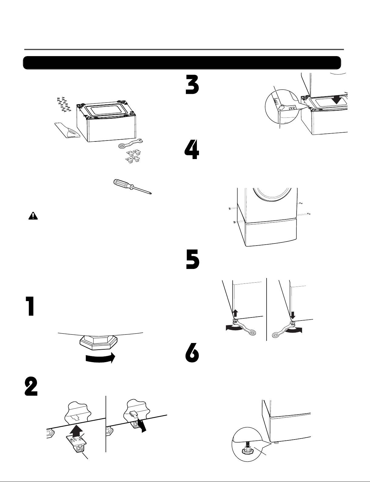
The pedestal accessory includes:
•Drawer divider (1) •Wrench (1)
•Screws (18) † •T-clips (4) ††
Tools Needed for Installation:
•Phillips-head screwdriver
•Wrench (supplied)
† Dryer installation only uses 8 screws
†† For dryer only
To ensure safe and secure installation, please
thoroughly follow the instructions below.
•Incorrect installation can cause serious accidents.
•The appliances are heavy. Two or more people are
required when installing the pedestal. There is a
risk of serious back injury or other injuries.
•Do not allow children to play in or on the drawer.
There is a risk of suffocation or injury.
•Do not step on the handle. There is a risk of serious injury.
•If appliances are already installed, disconnect them
from all power, water, or gas lines and from draining or
venting connections. Failure to do so can result in
electrical shock, fire, explosion, or death.
•When installing, gloves must be put on.
WARNING
Retract fully
Retainer
T-clip
Make sure the leveling feet of the dryer are
fully retracted.
NOTE: The appliance and pedestal assembly
must be placed on a solid, sturdy, level floor
for proper operation.
Insert the T-clip of the 4 retainers into the dryer
base as shown. Press up on the back of the
clip and pull outward to lock into place.
Place the dryer on the
pedestal. Make sure
the front and back feet
are in the correct
positions. The dryer
feet will fit into the
innermost positions as
shown.
Make sure the screws on the pedestal align with the
holes in the retainers, then install 4 screws on each
side to securely attach the appliance to the pedestal.
NOTE: If the screws are not installed properly, noise
and vibration may result.
Move the appliance to the desired location.
Securely tighten all locknuts by hand.
NOTE: Noise and vibration may result if locknuts are not
tightened.
Be sure to connect the appliances to all water, power,
or gas lines and draining or venting connections before
operation.
If there is excessive vibration during the first operation
after installation, slightly adjust the leveling feet.
Loosen the locknuts on all 4 leveling feet of the
pedestal until you can turn them with the wrench.
Turn clockwise to raise or counterclockwise to lower
until the pedestal is level and all 4 feet are solidly
against the floor.
For dryer
For washer/combo
Raise Lower
Locknut

9
Use the instructions under option 2 or 3 if your
home has a 3-wire receptacle (NEMA type 10-30R)
Use option 2 if local codes and ordinances permit
the connection of a chassis ground to the neutral
connector If this is not permitted, use option 3
3-2. Connecting Electric Dryers
If this type is available at your home you will be
connecting to a fused disconnect or circuit breaker
box
Grounding through the neutral conductor
is prohibited for (1) new branch-circuit installations,
(2) mobile homes, and (3) recreational vehicles, and
(4) areas where local codes prohibit grounding through
the neutral conductor
Prepare minimum 5 ft (1 52 m) of length in order for
dryer to be replaced
First, peel 5 inches (12 7 cm) of covering material from
end Make a 5 inches of ground wire bared After cutting
1
1
/2inches (3 8 cm) from 3 other wires peel insulation
back 1inch (2 5 cm) Make ends of 3 wires a hook
shape
Then, put the hooked shape end of the wire under the
screw of the terminal block(hooked end facing rightward)
and pinch the hook together and screw tightly
Use the instructions under option 1 if your home
has a 4-wire receptacle (NEMA type 14-30R)
If this type is available at your home you will be
connecting to a fused disconnect or circuit breaker
box
1 Connect neutral wire(white) of power cord to center
terminal block screw
2 Connect red and black wire to the left and right
terminal block screws
3 Connect ground wire(green) of power cord to external
ground screw and move neutral ground wire of
appliance and connect it to center screw
4 Make sure that the strain relief screw is tightened
and be sure that all terminal block nuts are on tight and
power cord is in right position
1"
(2.5 cm)
5"
(12.7 cm)
!"
!!"
5"
(12.7 cm)
#
1"
(2.5 cm)
5"
(12.7 cm)
F
ab
E
D
C

10
! " "
#
$ % &
'
(
' (
(
)(
(
* (
((
(
#
1"
(2.5cm)
3
(8.9 cm)
'
(
' (
(
'
+ ,
)(
(
$
-
.
'
Option 1
-
.
/
'
"
0#
#
# # #

11
1. Remove the appliance ground wire (D) (white)
from the external ground connector screw and
reconnect it, together with the center, white,
neutral wire (E) to the center, silver colored,
terminal block screw.
2. onnect the other two power cord wires (red and
black) to the left and right terminal block screws
and tighten securely.
3. Tighten the strain relief screws securely.
4. onnect an independent ground wire (F) from the
external ground connector screw to a proper
ground. (The ground wire must be long enough to
allow the appliance to be moved, if necessary, for
service or cleaning.)
B
A
lf your local codes or ordinances permit the
connection of a frame-grounding conductor to the
neutral wire, use these instructions. If your local
codes or ordinances do not allow the connection of
a frame-grounding conductor to the neutral wire,
use the instructions under
1. onnect the neutral (white or center) wire (B) to
the center, silver colored, screw (A) and tighten
securely.
2. onnect the other two power cord wires (red and
black) to the left and right terminal block screws
and tighten securely.
3. Tighten the strain relief screws ( ) securely.
Option 2
¥Ifyour local codes or ordinances do not allow the
connection of a frame-grounding conductor to the
neutral wire, use the instructions under this
section.
E
A
D
F
Option 3

12
3-2. Connecting the Gas Supply
2
3
5
1
4
1. Make certain your dryer is equipped for use with the
type of gas in your laundry room. Dryer is equipped
at the factory for Natural Gas with a 3/8ÓN Tgas
connection.
2. Remove the shipping cap from the gas connection
at the rear of the dryer. Make sure you do not
damage the pipe thread when removing the cap.
3. Connect to gas supply pipe using a new flexible
stainless steel connector.
4. Tighten all connections securely. Turn on gas and
check all pipe connections (internal and external) for
gas leaks with a non-corrosive leak detection fluid.
5. For L (Liquefied etroleum) gas connection, refer
to section on Gas Requirements.
For further assistance, refer to section
1 New Stainless Steel Flexible Connector - Use
only if allowed by local codes (Use Design
A.G.A. Certified Connector)
2
1
/
8
NPT Pipe Plug
(for checking inlet gas pressure)
3 Equipment Shut-Off Valve-Installed within 6
(1.8 m) of dryer
4 Black Iron Pipe
Shorter than 20 (6.1 m) - Use
3
/
8
pipe
Longer than 20 (6.1 m) - Use
1
/
2
pipe
5
3
/
8
NPT Gas Connection
Connecting gas dryers on Owner's Manual

Elec : 67
Gas : 63
Bulky/
Large
Perm.
Press
Cotton/
Normal
Delicates
Speed
Dry
Air Dry
Freshen
Up
NOTE The Energy Saver option is turned on by default in the Cotton/Normal cycle.
Turn Off the Energy Saver option for a faster Normal cycle which begins with heated drying.
To turn the Energy Saver default off, press and hold the Wrinkle Care button for three seconds.
ON or OFF appears in the display.
4DRYER CYCLE PROCESS
13

14
When checking the component, be sure to turn the power off, and do voltage discharge sufficiently.
!
CAUTION
1. Thermal cut off
Check Top Marking:
N140
Measure resistance of terminal
to terminal
Open at 284
(140
Same shape as outlet thermostat.
f thermal fuse is open must
be replaced
Resistance value
Heater case-
Safety
Electric type
2. Hi limit Thermostat
(Auto reset) Measure resistance of terminal
to terminal
Open at 257
(125
Close at 221
(94
Resistance value
Heater case -
Hi limit
Electric type
3. Outlet Thermostat
( Auto reset)
Check Top Marking:
N85
Measure resistance of terminal
to terminal
Open at 185
(85
Close at 167
(75
Same shape as thermal cut off.
Resistance value
Blow housing -
Safety
Electric type
4. Lamp holder Measure resistance of terminal
to terminal Resistance value:
80 ~ 100
6. dler switch Measure resistance of the
following terminal:
COM-NC
1. Lever open
2. Lever push (close)
Resistance value
5. Door switch Measure resistance of the
following terminal
1) Door open
Terminal: COM - NC (1-3)
Terminal: COM - NO (1-2)
2) Door closed
Terminal: COM - NC (1-3)
Terminal: COM - NO (1-2)
Resistance value
Resistance value
5COMPONENT TESTING INFORMATION

15
7. Heater Measure resistance of the
following terminal
Terminal: 1 (COM) - 2
Terminal: 1 (COM) - 3
Terminal:2-3
Resistance alue: 10
Resistance alue: 10
Resistance alue: 20
Electric type
8. Thermistor Measure resistance of terminal
to terminal
Temperature condition:
Resistance alue: 10 Heater case -
Hi limit
Electric type
9. Motor See Page 17
10. Gas al e al e 1
al e 2
Measure resistance of the
following terminal
Val e 1 terminal
Val e 2 terminal
Gas type
11. Igniter Measure resistance of terminal
to terminal Resistance alue: 50~800 Gas type
12. Flame Detect Measure resistance of terminal
to terminal
Resistance alue
Gas type

13. Outlet Thermostat
(Auto reset)
Check Top Marking:
N95
Measure resistance of terminal
to terminal
Open at 03
Close at 158
Resistance value
Gas type
Gas funnel
14. Outlet Thermostat
(Manual reset)
Check Top Marking:
N110
Measure resistance of terminal
to terminal
Open at 30
(110
Manual reset
Resistance value
Gas type
Gas funnel
16

6MOTOR DIAGRAM AND SCHEMATIC
17
Contact On / Off by Centrifugal Switch
STOP MODE
(When Motor does not operate)
RUN MODE
(Motor operates)
When checking component, be sure to turn power off, then do voltage discharge sufficiently.
NOTE
Centrifugal switch Centrifugal switch
(Pull Drive forward)

18
GN/YL
3 WIRE SYSTEM
EARTH
4 WIRE
SYSTEM
X1 X2
CN11
CN11
X1 X2
7WIRING DIAGRAM

19
( P/N : EBR64094887(Electric)
EBR64094888 (Gas )
Main PCB Picture
<Electric>
Tab relay(Black)
Tab relay(White) YL3
BL2
NA4 NA6
<Gas>
Tab relay(Black)
YL3
BL2
NA4
BL3
NA6

8FLOW SENSOR FUNCTION
20
How does the Flow sense function display the clogging of duct ?
This FlowSenseTM function detects the clogging or blocking of ducts.
Clogged duct vents or hoses decrease efficiency in drying cloths. Clogged vents can also cause fire.
This function alerts you to the need of cleaning the duct.
When the alarm about Duct clogging is on display of the panel, your duct vents should be cleaned by
yourself or serviceman.
The FlowSenseTM display consists of four bars inside
a box. The display has only 2 possible displays
as shown here (Also see the figure shown below):
No bars displayed.
4 bars displayed.
8-1 Flow sensor
Flow Sensor Function
4 Bars NO Bars
CLOGGED
Check and
Clean Duct.
Duct OK. The
Dryer can work.
NORMAL
1
2
This manual suits for next models
1
Table of contents
Other LG Dryer manuals
Popular Dryer manuals by other brands

Electrolux
Electrolux DC6-4 installation manual

GSA
GSA PMD Series instruction manual

Electrolux
Electrolux EIMED55IIW - 27" Electric Dryer Guía de Uso y Cuidado

GE
GE Spacemaker DSXH47 Owner's manual and installation instructions

Samsung
Samsung DV520AE-02836A-01 user manual

Electrolux
Electrolux EDH 97981W user manual