LG DLE8377WM User manual

U.S.A. Website: http://us.lgservice.com
Canadian Website: http://lg.ca
ELECTR C & GAS DRYER
SERVICE MANUAL
CAUTION
READ TH S MANUAL CAREFULLY N ORDER TO
PROPERLY D AGNOSE PROBLEMS AND TO SAFELY
PROV DE QUAL TY SERV CE ON THESE DRYERS.
MODEL : DLE8377WM/DLG8388WM
DLE8377NM/DLG8388NM
DLE7177WM/DLG7188WM

JAN. 2006 PR NTED N KOREA
P/No.:3828EL3005D

2
To avoid personal injury, disconnect power before servicing this product. If electrical power is required
for diagnosis or test purposes, disconnect the power immediately after performing the necessary checks.
!
WARNING !
WHAT TO DO IF YOU SMELL GAS:
IMPORTANT SAFETY NOTICE
The information in this service guide is intended for use by individuals possessing skill and experience in
electrical, electronic, and mechanical appliance repair. Any attempt to repair a major appliance may result
in personal injury and property damage. The manufacturer or seller cannot be responsible for the
interpretation of this information, nor can it assume any liability in connection with its use.
RECONNECT ALL GROUNDING DEVICES
f grounding wires, screws, straps, clips, nuts, or washers used to complete a path to ground are
removed for service, they must be returned to their original position and properly fastened.
IMPORTANT
Electrostatic Discharge (ESD)
Sensitive Electronics
ESD problems are present everywhere. ESD may damage or weaken the electronic
control assembly. The new control assembly may appear to work well after repair is
finished, but failure may occur at a later date due to ESD stress.
Use an anti-static wrist strap. Connect wrist strap to green ground connection point or unpainted
metal in the appliance.
- OR -
Touch your finger repeatedly to a green ground connection point or unpainted metal
in the appliance.
Before removing the part from its package, touch the anti-static bag to a green ground connection
point or unpainted metal in the appliance.
Avoid touching electronic parts or terminal contacts; handle electronic control assembly by edges only.
When repackaging failed electronic control assembly in anti-static bag, observe above instructions.
■Do not try to light a match, or cigarette, or turn on
any gas or electrical appliance.
■Do not touch any electrical switches. Do not use any
phone in your building.
■Clear the room, building or area of all occupants.
■Immediately call your gas supplier from a neighbor’s
phone. Follow the gas supplier’s instructions
carefully.
■If you cannot reach your gas supplier, call the fire
department.

3
1. SPECIFICATIONS ..................................................................................................................4
2. FEATURES AND BENEFITS .................................................................................................... 6
3. INSTALLATION INSTRUCTIONS ........................................................................................... 6
4. DRYER CYCLE PROCESS..................................................................................................... 13
5. COMPONENT TESTING INFORMATION ..............................................................................14
6. MOTOR DIAGRAM AND SCHEMATIC..................................................................................17
7. CONTROL LAYOUT ............................................................................................................18
8. WIRING DIAGRAM ............................................................................................................19
9. DIAGNOSTIC TEST .............................................................................................................20
9-1. TEST 1 120V AC ELECTRICAL SUPPLY ........................................................................21
9-2. TEST 2 THERMISTOR TEST .........................................................................................22
9-3. TEST 3 MOTOR TEST ................................................................................................24
9-4. TEST 4 MOISTURE SENSOR ....................................................................................25
9-5. TEST 5 DOOR SWITCH TEST ...................................................................................26
9-6. TEST 6 HEATER SWITCH TEST - ELECTRIC MODEL.......................................................27
9-7. TEST 7 GAS VALVE TEST - GAS MODEL.....................................................................28
9-8 TEST 8 SEMI-CONDUCTOR..........................................................................................29
10. CHANGE GAS SETTING (NATURAL GAS, PROPANE GAS) ...............................................30
11. DISASSEMBLY INSTRUCTIONS .........................................................................................32
12. EXPLODED VIEW ..............................................................................................................39
12-1. CONTROL PANEL & PLATE ASSEMBLY .......................................................................39
12-2. CABINET & DOOR ASSEMBLY...................................................................................40
12-3-1. DRUM & MOTOR ASSEMBLY: ELECTRIC MODEL......................................................41
12-3-2. DRUM & MOTOR ASSEMBLY: GAS MODEL ............................................................42
13. REPLACEMENT PARTS LIST.................................................................................................43
CONTENTS

44
SPECIFICATIONS
1
■Name: Electric and Gas Dryer
■Power supply: Please refer to the rating label regarding detailed
information.
■Size: 27 X 29.9 X 38.7 (inch)
■Dryer capacity: EC 7.3 cu.ft.
■Weight: 126( bs)
Specifications are subject to change by manufacturer.
■ ACCESSORIES
Dryer rack (1 each) Stacking kit (1 each)
Purchased Separately
Pedestal (1 each)
Purchased Separately
See page 6 See page 7 See page 8

5
Temperature
Moisture
High/Low/Off
Sensor
5
124/144
Door Trim
Top Plate
Color
Chromate
Por elain
Blue White Navy Blue
120V/240V 60Hz (26A)
POWER SUPPLY
LAMP
HEATER
MOTOR
3
9
7.3 u.ft.
Ele troni
GAS VALVE
5400W (22.5A)
5
250W (4.5A)
15 W (125mA)
13 W (110mA) x 2
ELECTRICITY
CONSUMPTION
Material &
Finish
DLE7177WM/DLE8377WM
DLG7188WM/DLG8388WM
DLE8377NM
DLG8388NM
ITEM
Child Lo k
Reversible Door
Interior Light
Produ t (WxHxD)
Pa king (WxHxD)
Sound levels
Dryer Ra k
Drum
No. of Dry Levels
No. of Dry Options
No. of Programs
DRUM CAPACITY
CONTROL TYPE
No. of Temperature Controls
Weight (lbs) - Net/Gross
AC 120V
(GAS MODEL)
AC 240V
(ELECTRIC MODEL)
Ele trode sensor
Thermistor
AC 120V
AC 120V
REMARK
Available
Available
Available
Available
Avaiable
Avaiable
27" x 42 3/4" x 28 1/3"
29 1/2" x 44 3/4" x 30 3/4"
Stainless Steel

6
FEATURES AND BENEFITS
2
NORMAL
20%
MEDIUM OFF MID
HIGH
SENSOR DRY
NORMAL
0:20
EST. TIME
REMAINING
INSTALLATION INSTRUCTIONS
3
Open the door.
Hold the dryer ra k
with both hands.
Put the dryer ra k into
the drum
Che k and be sure that the
front of the ra k is properly
seated behind the lint filter.
123
Dryer Rack Installation Instructions

7
To ensure safe and secure installation, please observe the instructions below.
Place the washer firmly on a stable, even
and solid floor as product installation
instructions describe in the owner’s
manual.
Peel the protective paper from the tape on
the side bracket.
Fit the side bracket firmly to the side of the
top plate by attaching the double-faced tape
to the top plate as picture shown.
Secure the side bracket to the washer with
a screw on the back of the bracket. Repeat
Steps 2, 3, & 4 for the other side.
Place the dryer on top of the washer by
placing the legs as shown. Be careful not to
pinch fingers between the washer and dryer.
Slide the dryer back against the stop on the
side rail.
nsert the front rail of the stacking kit. Push
the front rail back against the stops on the
side brackets.
• Do not use a stacking kit with a gas dryer in
potentially unstable conditions like a mobile
home.
Stacking kit
Do not attempt this alone!
At least two people are required to lift and
position the dryer on top of a washing
machine!
Failure to heed this warning can result in
serious physical injury and damage to the
appliance.
WARNING
1
2
3
4
5
6
7
Stacking Kit Installation Instructions
Screw both sides of the front rail to the side
brackets.

8
For washer, dryer, and ombo LG 27”
25 3/8
?
(64.5cm)
2.86?
(7cm)
18 3/4
(47.5 cm)
27?
(68.6cm)
7 1/4
(18.4cm)
Pedestal Installation Instructions
4Attach the double-faced tape of the bracket to the
dryer as shown so the bent parts of the brackets
align with the edge and can be attached to the
pedestal with screws.
NOTE :
Attach the lower side first.
5Be sure to press the adhesive parts of the brackets
firmly to the appliance.
6nstall the eight (8) screws(supplied) to attach the
brackets to the pedestal.
7Move the dryer to the desired place.
NOTE :
The appliance and pedestal assembly
must be placed on a solid and level floor
for proper operation. Adjust the legs of the
appliance and pedestal by turning with a
wrench. Then, adjust the lock unt toward
the pedestal while holding the pedestal leg
using a wrench.
1Remove pedestal, installation hardware, and
instructions from the shipping carton.
2Position the dryer on top of the pedestal.
,
.
3Remove the paper from the
bracket.
for washer/
combo
for washer/
combo
for dryer
for dryer
NOTE: That the Pedestal
hardware packet may in-
clude 2 sets of side
brackets. Be sure to use
the brackets marked for
the dryer.
After removing the protective covering from the
adhesive surface, align the screw holes in the
brackets with the matching holes in the pedestal
base and press and press the brackets against
the base and the dryer.

9
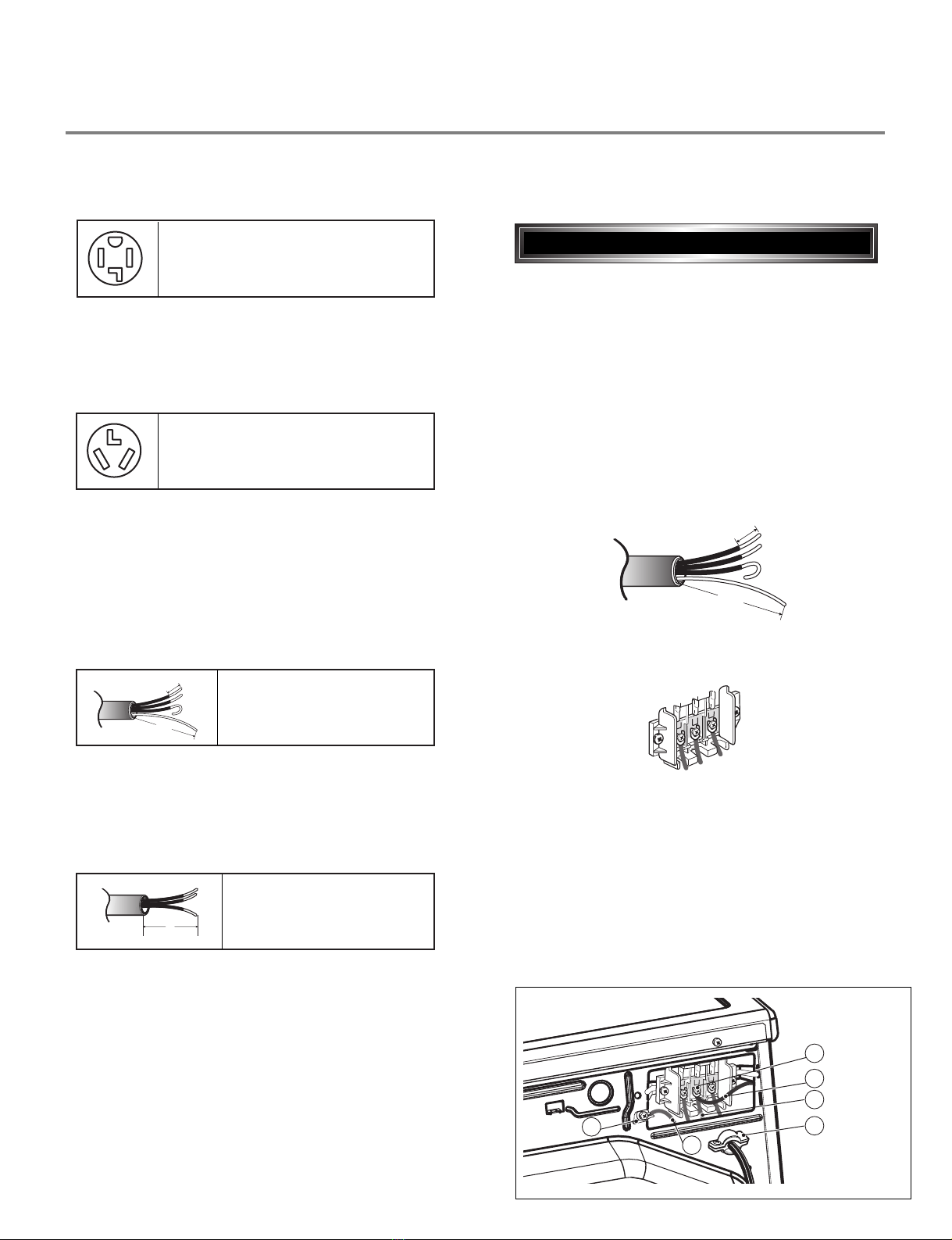
Use the instructions under option 2 or 3 if your
home has a 3-wire receptacle (NEMA type 10-30R).
Use option 2 if local codes and ordinances permit
the connection of a chassis ground to the neutral
connector. If this is not permitted, use option 3.
Review the following options to determine the appropriate electrical connection for your home:
Electric Dryer Only
If this type is available at your home. you will be
connecting to a fused disconnect or circuit breaker
box
Important : Grounding through the neutral conductor
is prohibited for (1) new branch-circuit installations,
(2) mobile homes, and (3) recreational vehicles, and
(4) areas where local codes prohibit grounding through
the neutral conductor.
Prepare minimum 5ft(1.52m) of length in order for
dryer to be replaced.
First, peel 5 inch (12.7cm) of covering material from
end. Make a 5 inch of ground wire bared. After cutting
1
1
/2inch (3.8cm) from 3 other wires. peel insulation
back 1inch (2.5cm). Make ends of 3 wires a hook
shape.
Then, put the hooked shape end of the wire under the
screw of the terminal block(hooked end facing rightward)
and pinch the hook together and screw tightly.
Use the instructions under option 1 if your home
homehas a 4-wire receptacle (NEMA type 14-30R).
If this type is available at your home. you will be
connecting to a fused disconnect or circuit breaker
box
1. Connect neutral wire(white) of power cord to center
terminal block screw.
2. Connect red and black wire to the left and right
terminal block screws.
3. Connect ground wire(green) of power cord to external
ground screw and move neutral ground wire of
appliance and connect it to center screw.
4. Make sure that the strain relief screw is tightened.
and be sure that all terminal block nuts are on tight and
power cord is in right position.
5"
(12.7 m)
31/2"
(8.6 m)
1"
(2.5 m)(2.5 m)
5"
(12.7 m)(12.7 m)
1"
(2.5 m)
3V2"
(8.9 m)
3-wire direct
4-wire receptacle
(NEMA type14-30R)
3-wire receptacle
(NEMA type10-30R)
4-wire direct
5"5"
(12.7 m)(12.7 m)
31/2"
(8.6 m)
1"
(2.5 m)
5"
(12.7 m)
1"
(2.5 m)
3V2"
(8.9 m)
4-wire connection : Direct wire
5"
(12.7 m)
31/2"
(8.6 m)
1"1"
(2.5 m)(2.5 m)
5"
(12.7 m)(12.7 m)
1"
(2.5 m)
3V
2
"
(8.9 m)
F
a
b
E
D
C

10
Important : Grounding through the neutral conductor
is prohibited for (1) new branch-circuit installations,
(2) mobile homes, and (3) recreational vehicles, and
(4) areas where local codes prohibit grounding through
the neutral conductor.
Prepare minimum 5ft(1.52m) of length in order for
dryer to be replaced.
First, peel 3 1/2inch (8.9cm) of covering material
from end and bare 1 inch from the ends.
1. Connect neutral wire(white) of power cord to
center terminal block screw.
2. Connect red and black wire to the left and right
terminal block screws.
3. Make sure that the strain relief screw is tightened
and be sure that all terminal block nuts are on
tight and power cord is in right position.
Then, put the hooked shape end of the wire under
the screw of the terminal block(hooked end facing
rightward) and pinch the hook together and screw
tightly.
5"
(12.7 m)
31/2"
(8.6 m)
1"
(2.5 m)
5"
(12.7 m)
1"
(2.5 m)
3V3V2"
(8.9 m)(8.9 m)
3-wire connection : Direct wire
1. Connect the neutral wire (white) of the power
cord to the center terminal block screw.
2. Connect the red and black wires to the left and
right terminal block screws.
3. Connect the ground wire (green) of the power
cord to the external ground screw. Remove the
neutral ground wire of appliance and connect it to
center screw.
4. Make sure that the strain relief screw is tightened
and that all terminal block nuts are tight and the
power cord is in the right position.
F
a
b
E
D
C
• lf your local codes or ordinances do not allow the
use of a 3 wire connection, or you are installing
your dryer in a mobile home, you must use a 4-
wire connection.
Option 1: 4-wire connection with
a Power supply cord.
E
a
D
B
C

11
1. Remove the appliance ground wire (D) (green)
fromthe external ground connector screw and
reconnect it, together with the center, white,
neutral wire (E) to the center, silver colored,
terminal block screw.
2. Connect the other two power cord wires (red and
black) to the left and right terminal block screws
and tighten securely.
3. Tighten the strain relief screws securely.
4. Connect an independent ground wire (F) from the
external ground connector screw to a proper
ground. (The ground wire must be long enough to
allow the appliance to be moved, if necessary, for
service or cleaning.)
C
B
A
lf your local codes or ordinances permit the
connection of a frame-grounding conductor to the
neutral wire, use these instructions. If your local
codes or ordinances do not allow the connection of
a frame-grounding conductor to the neutral wire,
use the instructions under Section 3: Optional
3-wire connection.
1. Connect the neutral (white or center) wire (B) to
the center, silver colored, screw (A) and tighten
securely.
2. Connect the other two power cord wires (red and
black) to the left and right terminal block screws
and tighten securely.
3. Tighten the strain relief screws (C) securely.
Option 2: 3-Wire Connection with
a Power Supply Cord
• If your local codes or ordinances do not allow the
connection of a frame-grounding conductor to the
neutral wire, use the instructions under this
section.
E
A
D
F
Option 3: Optional 3-wire
connection.

12
3-2. Connect Gas Supply Pipe (Gas Dryer ONL )
2
3
5
1
4
1. Make certain your dryer is equipped for use with the
type of gas in your laundry room. Dryer is equipped
at the factory for Natural Gas with a 3/8” N.P.T. gas
connection.
2. Remove the shipping cap from the gas connection
at the rear of the dryer. Make sure you do not
damage the pipe thread when removing the cap.
3. Connect to gas supply pipe using a new flexible
stainless steel connector.
4. Tighten all connections securely. Turn on gas and
check all pipe connections (internal & external) for
gas leaks with a non-corrosive leak detection fluid.
5. For L.P. (Liquefied Petroleum) gas connection, refer
to section on Gas Requirements.
For further assistance, refer to section on Gas Requirements.
1 New Stainless Steel Flexible Connector - Use
only if allowed by local codes (Use Design
A.G.A. Certified Connector)
2 1/8” N.P.T. Pipe Plug
(for checking inlet gas pressure)
3 Equipment Shut-Off Valve-Installed within 6’
(1.8 m) of dryer
4 Black Iron Pipe
Shorter than 20’ (6.1 m) - Use 3/8” pipe
Longer than 20’ (6.1 m) - Use 1/2” pipe
5 3/8” N.P.T. Gas Connection

13
DRYER CYCLE PROCESS
4
Time
Cycle
HEAVY DUTY
3Hr
3Hr
Off Time: 6min
On Time: 10sec
Temperature Control for each cycle
H GH
M D
H GH
MED UM
LOW
LOW
ULTRA
LOW
(H GH)
(M D
H GH)
COTTON/
TOWELS
NORMAL
PERM
PRESS
DEL CATES
ULTRA
DEL CATE
SPEED DRY
FRESHEN UP
A R DRY
-
(Normal)
(Normal)
(Normal)
(Normal)
(Normal)
(Normal)
-
-
-
54min Saturation
Saturation
Saturation
Saturation
Saturation
Saturation
Saturation
Saturation
55min
41min
36min
32min
34min
25min
20
min
30
min
(5min)
(5min)
(5min)
(5min)
(5min)
(5min)
(5min)
(5min)
N/A
68±4°C
66±4°C
60±4°C
52±3°C
52±3°C
45±3°C
(70±5°C)
(66±5°C)
No
heater
47±5°C
47±5°C
47±5°C
47±5°C
38±5°C
38±5°C
(47±5°C)
(47±5°C)
N/A
Saturation
Load
Sensor
Dry *
Manual
Dry **
Default
Drying
Electro-
sensor
Temp-
Control
Default
time
Temp-
Control **
Cooling Wrinkle care
Conditions of operation and termination
Temp-
erature
Dry
Level
Display
time
Motor
Heater
* Sensor dry : “Dry Level” is set by users.
** Manual dry : “Temperature control” is set by users.
Default settings can be adjusted by users.

14
When checking the Component, be sure to turn the power off, and do voltage discharge sufficiently.
COMPONENT TESTING INFORMATION
5
!
CAUTION
Component Test Procedure Check result Remark
1. Thermal cut off
• Check Top Marking:
N130
Measure resistance of terminal
to terminal
Open at 266 ±12°F
(130 ±7°C)
Auto reset 31°F (35°C)
Same shape as Outlet Thermostat.
f thermal fuse is open must
be replaced
Resistance value ≒∞
Continuity (250°F ) < 1Ω
• Heater case-
Safety
• Electric type
2. Hi limit Thermostat
(Auto reset)
Measure resistance of terminal
to terminal
Open at 257 ±9°F
(125 ±5°C)
Close at 221 ±9°F
(105 ±5°C)
Resistance value ≒∞
Resistance value < 5Ω
• Heater case -
Hi limit
• Electric type
3. Outlet Thermostat
( Auto reset)
• Check Top Marking:
N85
Measure resistance of terminal
to terminal
Open at 185 ±9°F
(85 ±5°C)
Close at 149 ±9°F
(65 ±5°C)
Same shape as Thermal cut off.
Resistance value ≒∞
Resistance value < 5Ω
• Blow housing -
Safety
• Electric type
4. Lamp holder Measure resistance of terminal
to terminal
Resistance value:
80Ω ~ 100Ω
6. dler switch Measure resistance of the
following terminal:
“COM - NC”
1. lever open
Resistance value < 1Ω
2. Lever push (close)
Resistance value ≒∞
5. Door switch Measure resistance of the
following terminal
1) Door switch knob: open
Terminal: “COM” - “NC” (1-3)
Terminal: “COM” - “NO” (1-2)
2) Door switch push: push
Terminal: “COM” - “NC” (1-3)
Terminal: “COM” - “NO” (1-2)
Resistance value < 1Ω
Resistance value ≒∞
Resistance value ≒∞
Resistance value < 1Ω
The state that
Knob is
pressed is
opposite to
Open
condition.

15
Component Test Procedure Check result Remark
7. Heater Measure resistance of the
following terminal
Terminal: 1 (COM) - 2
Terminal: 1 (COM) - 3
Terminal: 2 - 3
Resistance value: 10Ω
Resistance value: 20Ω
• Electric type
8. Thermistor Measure resistance of terminal
to terminal
Temperature condition:
58°F ~ (10~40°C)
58°F ~ 104F (10~40°C)
Resistance value: 10Ω • Heater case -
Hi limit
• Electric type
9. Motor • See Page 13
10. Gas valve valve 1
valve 2
Measure resistance of the
following terminal
Valve 1 terminal
Valve 2 terminal
Resistance value: > 1.5 kΩ
Resistance value: >
1.5~2.5 kΩ
• Gas type
11. gniter Measure resistance of terminal
to terminal
Resistance value: 100~800Ω • Gas type
12. Frame Detect Measure resistance of terminal
to terminal
Open at 370°F ((Maximum)
Close at 320°F
Resistance value ≒∞
Resistance value < 1Ω
• Gas type

16
Component Test Procedure Check result Remark
13. Outlet Thermostat
(Auto reset)
• Check Top Marking:
N95
Measure resistance of terminal
to terminal
Open at 203 ±7°F (95 ±5°C)
Close at 158 ±9°F (70 ±5°C)
Resistance value ≒∞
Continuity < 1Ω
• Gas type
• Gas funnel
14. Outlet Thermostat
(Manual reset)
• Check Top Marking:
N100
15. Semi-Conductor
Measure resistance of terminal
to terminal
Open at 212 ±12°F
(100 ±7°C)
Manual reset
Measure resistance of
terminal to terminal
Red-White :
300 ±20 Ω
White-Black :
300 ±20 Ω
f thermal fuse is open must
be replaced
Resistance value ≒∞
Continuity < 1Ω
Resistance value ≒∞
Continuity < 1Ω
• Gas type
• Gas funnel
• Elect type
• Gas type
BW
R

17
MOTOR DIAGRAM AND SCHEMATIC
6
Contact On / Off by Centrifugal Switch
STOP MODE
(When Motor does not operate)
RUN MODE
(Motor operates)
When checking Component, be sure to turn Power off, then do voltage discharge sufficiently.
NOTE
Centrifugal switch Centrifugal switch
(Pull Drive forward)

18
CONTROL LAY - OUT
7
PWB ASSEMBLY DISPLAY LAYOUT
PWB ASSEMBLY LAYOUT
MODEL D SPLAY AS D AGNOST C TEST
MODEL
DLE8377WM/
DLE8377NM
DLG388WM/
DLG8388NM
DP 1
XX
X
DP 3 OP 5
6871EL1011A
ELETRIC
OX
X
6871EL1011B
GAS
OPTION PART LED
DISPLAY P/No
MODEL AS D AGNOST C TEST
MODEL
DLE8377WM/
DLE8377NM
DLG388WM/
DLG8388NM
XXX
X
OO
6871EL1013D6170EC1006F
6170EC1006F 6871EL1013C
"a" RLY200 “b”x5
“c” TRANS
P/No
MICOM

19
ELECTRIC DRYER WIRING DIAGRAM
WIRING DIAGRAM
8
MOISTURE
SENSOR
BLACK
WHITE
RED
GRAY
LAMP
MEDOM CLP
1
2
1
3
2
4
8
7
6
5
4
3
2
1
ELECTRONIC CONTROL
HI - LIMIT THERMOSTAT
WH1
TRANS
ETIHW
KCA;B
DER
N WHITE
L2
WHITE
BLOWER
THERMOSTAT
RED
YELLOW
HEATER
BLUE
RED
BELT
SWITCH
L1 BLACK
NWORB
ETIHW
LIOC RENNI
LIOC RETUO
EULB
WOLLEY
DER
NWORB
BL2 NA6
DOOR SWITCH
NC
NO
COM
23
1
1
31
1
2
3
OVERLOAD
PROTECTOR
MOTOR
LAGUFIRTNEC
HCTIWS
YTEFAS TATSOMREHT
TAP RELAY
BLACK TAP RELAY
WHITE
21 3 7
10
DER
EGNARO
EULB
6 5 34 2 1
2 1 2 1
THERMISTOR
MOISTURE
SENSOR
GAS DRYER WIRING DIAGRAM
GRAY
LAMP
MEDOM CLP
1
2
1
3
2
4
8
7
6
5
4
3
2
1
BLACK
WHITE
RED
MOISTURE
SENSOR
ELECTRONIC CONTROL
SAFETY THERMOSTAT
HI-LIMIT
THERMOSTAT
BLOWER
THERMOSTAT
OVERLOAD
PROTECTOR
DOOR SWITCH
GRAY
NC
NO
BL2 YL2
WH1 TRANS BL3 NA6
COM
ETIHW
N WHITE
WHITE
YELLOW
RED
THERMISTOR
MOISTURE
SENSOR
DC VALVE1
FLAME
DETECTOR
IGNITER
MOTOR
NC NO
BELT
SWITCH
TAP RELAY
BLACK
DC VALVE2
L1 BLACK
GN/YL
POWER CORD
NWORB
NWORB
YARG
EULB
ETIHW
EULB EULB
EULB
EGNARO
DER
DER
DER
KNIP
ETIHW
WOLLEY
LAGUFIRTNEC
HCTIWS
23
1
1
3113
2
1
3
2 3 7 9
2 3
6 5 31 2 3 4 2 1
1 2 1 2
2 1 2 1
BLUE
Other manuals for DLE8377WM
3
This manual suits for next models
5
Table of contents
Other LG Dryer manuals
Popular Dryer manuals by other brands

Johnson
Johnson JDRY Series instruction manual

Frigidaire
Frigidaire Affinity FAQG7077K W Specification sheet

Warner Howard
Warner Howard EI1100W instructions

Maytag
Maytag MDE20PD User instructions

Beko
Beko DVTC710W Installation & operating instructions and drying guidance

FUST
FUST Novamatic TW727.2 E user manual

Russell Hobbs
Russell Hobbs RH3VTD800 instruction manual

ADC
ADC AD-310 Service manual

Siemens
Siemens iQ800 WT48Y800GB instruction manual

Whirlpool
Whirlpool CGM2751TQ - COMM GAS DRYR 3CYC 3TEMP 3LITE Brochure & specs

Insignia
Insignia NS-TDRE75W1 user guide

Mediclinics
Mediclinics M96A Installation and operating manual