LG 42700H - 42INCH CLASSHDTV Quick start guide

Lifds Good
LCD TV
OWNER'S MANUAL
32LG700H
37LG700H
42LG700H
Installer Reference for Commercial Mode
MPI/PPV Card Setup see page 19
Commercial Mode Setup see pages 85-107
Please read this manual carefully before operating
your set.
Retain it for future reference.
Record model hum
See the
tl dealer
service.
of the set.
:k cover and quote
leh
Serial:
This product qualifies for ENERGYSTARin the "factory
default" setting and this isthe setting in which power savings
will be achieved.
Changing the factory default picture setting or enabling other
features will increasepower consumption that could exceed
the limits necessary to quality for EnergyStar rating.
1-800-243-0000 usA_c_s_m__us_,
1-888-865-3026 usA__:_mm_oda_us__
1-888-542-2623 C,_NADA
P/NO :SAC30708043 (0902-REV03)

WARNING /CAUTION
WARNING/CAUTION
To prevent fire or shock hazards, do not expose
this product to rain or moisture.
WARNING/CAUTION
TO REDUCE THE RISK OF FIREAND ELECTRIC
SHOCK. DO NOT EXPOSE THIS PRODUCT TO
RAIN OR MOISTURE.
This reminder is provided to call the CATV system
installer's attention to Article 820-40 of the National
Electric Code (U.S.A.). The code provides guidelines for
proper grounding and, in particular, specifies that the
cable ground shall be connected to the grounding system
of the building, as close to the point of the cable entry
as practical.
Class B digital device
This equipment has been tested and found to comply
with the limits for a Class B digital device, pursuant to
Part 15 of the FCC Rules. These limits are designed
to provide reasonable protection against harmful
interference in a residential installation. This equipment
generates, uses and can radiate radio frequency energy
and, if not installed and used in accordance with the
instructions, may cause harmful interference to radio
communications. However, there is no guarantee that
interference will not occur in a particular installation.
If this equipment does cause harmful interference to
radio or television reception, which can be determined
by turning the equipment off and on, the user is
encouraged to try to correct the interference by one
or more of the following measures:
- Reorient or relocate the receiving antenna.
- Increase the separation between the equipment and
receiver.
- Connect the equipment to an outlet on a circuit
different from that to which the receiver is connected.
-Consult the dealer or an experienced radio/TV
technician for help.
This device complies with part 15 of the FCC Rules.
Operation is subject to the following two condi-
tions: (1) This device may not cause (harmful)
interference, and (2) this device must accept any
interference received, including interference that
may cause undesired operation (of the device).
Any changes or modifications in construction of this
device which are not expressly approved by the party
responsible for compliance could void the user's
authority to operate the equipment.
Do not attempt to modify this product in any way
without written authorization from LG Electronics.
Unauthorized modification could void the user's
authority to operate this product

SAFETYINSTRUCTIONS
IMPORTANT SAFETYINSTRUCTIONS
Read these instructions.
Keep these instructions.
Heed all warnings.
Follow all instructions.
O Do not usethis apparatus near water.
Clean only with dry cloth.
Do not block ventilation openings. Install in
any
accordance with the manufacturer's instructions.
0Do not install near any heat sources such as
radiators, heat registers, stoves, or other apparatus
(including amplifiers)that produce heat.
0Do not defeat the safety purpose of the polarized
or grounding-type plug. A polarized plug has
two blades with one wider than the other. A
grounding type plug has two blades and a third
grounding prong, The wide blade or the third
prong are provided for your safety. If the provided
plug does not fit into your outlet, consult an
electrician for replacement of the obsolete outlet.
0Protect the power cord from being walked on
or pinched particularly at plugs, convenience
receptacles, and the point where they exit from
the apparatus.
Only use attachments/accessories specified by
the manufacturer.
0Use only with the cart, stand, tripod, bracket,
or table specified by the manufacturer, or sold
with the apparatus. When a cart is used, use
caution when moving the cart/apparatus
combination to avoid injury from tip-over.
Unplug this apparatus during lighting storms or
when unused for long periods of time.
Refer all servicing to qualified service personnel.
Servicing is required when the apparatus has been
damaged in any way,such as power-supply cord or
plug is damaged, liquid has been spilled or objects
have fallen into the apparatus, the apparatus has
been exposed to rain or moisture, does not operate
normally, or has been dropped.
2

O
®
®
O
Never touch this apparatus or antenna during a
thunder or lighting storm.
When mounting a TV on the wall, make sure not to
install the TV by the hanging power and signal
cables on the back of the TV.
Do not allow an impact shock or any objects to fall
into the product, and do not drop onto the screen
with something.
CAUTION concerning the Power Cord :
It is recommend that appliances be placed upon a
dedicated circuit; that is,asingle outlet circuit which
powers only that appliance and has no additional
outlets or branch circuits. Check the specification
page of this owner's manual to be certain.
Do not connect too many appliances to the same
AC power outlet as this could result in fire or elec-
tric shock.
Do not overload wall outlets. Overloaded wall out-
lets, loose or damaged wall outlets, extension cords,
frayed power cords, or damaged or cracked wire
insulation are dangerous. Any of these conditions
could result in electric shock or fire. Periodically
examine the cord of your appliance, and if its
appearance indicates damage or deterioration,
unplug it, discontinue use of the appliance, and
have the cord replaced with an exact replacement
part by an authorized servicer. Protect the power
cord from physical or mechanical abuse, such as
being twisted, kinked, pinched, closed in a door, or
walked upon. Payparticular attention to plugs, wall
outlets, and the point where the cord exits the
appliance.
Do not make the TV with the power cord plugged
in. Do not use a damaged or loose power cord. Be
sure do grasp the plug when unplugging the power
cord. Do not pull on the power cord to unplug the
TV.
O
@
O
O
WARNING - To reduce the risk of fire or electrical
shock, do not expose this product to rain,moisture
or other liquids. Do not touch the TV with wet
hands. Do not install this product near flammable
objects such as gasoline or candles or expose the
TV to direct air conditioning.
Do not exposeto dripping or splashingand do not
placeobjectsfilledwith liquids,suchasvases,cups,
etc.on or overthe apparatus(e.g.on shelvesabove
the unit).
GROUNDING
Ensure that you connect the earth ground wire to
prevent possible electric shock (i.e. a TV with a
three-prong grounded AC plug must be connected
to a three-prong grouned AC outlet) If grounding
methods are not possible, have a qualified electri-
cian install a separate circuit breaker.
Do not try to ground the unit by connecting it to
telephone wires, lightening rods, or gas pipes.
Short-circuit
Breaker
Power
Supply
DISCONNECTING DEVICE FROM MAINS
Mains plug is the disconnecting device. The plug
must remain readily operable.
3

ANTENNAS
Outdoor antenna grounding
Ifan outdoor antenna is installed, follow the precau-
tions below. An outdoor antenna system should not
be located in the vicinity of overhead power lines or
other electric light or power circuits, or where it can
come in contact with such power lines or circuits as
death or serious injury can occur.
Besurethe antenna system isgrounded so asto pro-
vide some protection against voltage surges and
built-up static charges.
Section 810 of the National Electrical Code (NEC) in
the U.S.A.provides information with respect to prop-
er grounding of the mast and supporting structure,
grounding of the lead-in wire to an antenna dis-
chargeunit, sizeof grounding conductors, location of
antenna discharge unit, connection to grounding
electrodes and requirements for the grounding elec-
trode.
Antenna grounding according to the
National Electrical Code, ANSI/NFPA 70
Ground Clamp
NEC: National Electrical Code
Antenna Lead in Wire
Antenna Discharge Unit
(NEC Section 810-20)
Grounding Conductors
(NEC Section 810-21)
Ground Clamps
Power Service Grounding
Electrode System (NEC
Arf 250, Part H)
Cleaning
When cleaning, unplug the power cord and scrub
gently with a soft cloth to prevent scratching. Do not
spray water or other liquids directly on the TV as
electric shock may occur. Do not clean with chemi-
cals such as alcohol, thinners or benzene.
O Moving
Make sure the product is turned off, unplugged
and all cables havebeen removed. It may take 2 or
more people to carry larger TVs. Do not press
against or put stress on the front panel of the TV.
O
@
Ventilation
Install your TV where there isproper ventilation. Do
not install in a confined space such as a bookcase.
Do not cover the product with cloth or other mate-
rials (e.g.) plastic while plugged in. Do not install in
excessivelydusty places.
Ifyou smell smoke or other odors coming from the
TV or hear strange sounds, unplug the power cord
contact an authorized service center.
Do not strongly the panel with ahand or
press upon
sharp object such as nail, pencil or pen, or make a
scratch on it
l!_ Keep product away sunlight.
the from direct
For LCD TV
If the TV feels cold to the touch, there may be
a small "flicker" when it is turned on. This is
normal, there is nothing wrong with TV.
Some minute dot defects may be visible on the
screen, appearing as tiny red, green, or blue
spots. However, they have no adverse effect on
the monitor's performance.
Avoid touching the LCD screen or holding your
finger(s) against it for long periods of time.
Doing so may produce some temporary dis-
tortion effects on the screen.
ON DISPOSAL
(Only Hg lamp used LCD TV)
The fluorescent lamp used in this product contains
asmall amount of mercury. Do not dispose of
this product with general household waste.
Disposal of this product must be carried out in
accordance to the regulations ofyour local authority.
4

CONTENTS
WARNING /CAUTION ............................ 1
SAFETY INSTRUCTIONS ..........................2
FEATURES OF THIS TV ............................. 7
PREPARATION
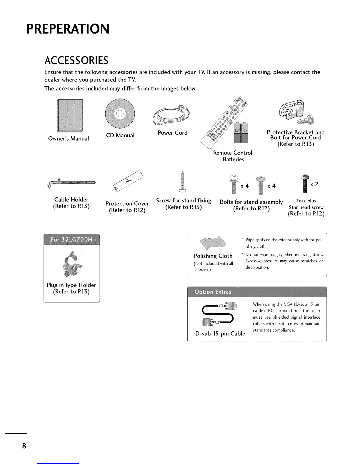
Accessories ...................................................... 8
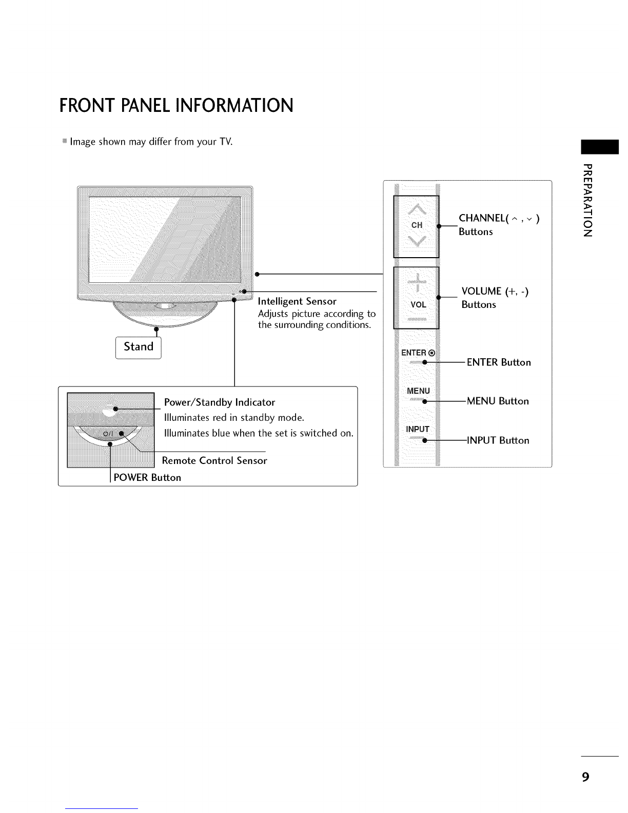
Front Panel Information ..................................... 9
Back Panel Information .................................... 10
Stand Instruction ............................................. 12
Cable Management ......................................... 13
Desktop Pedestal Installation ............................ 14
Swivel Stand.................................................... 14
Attaching the TV to a desk ............................... 15
VESAWall Mounting ........................................ 16
Securing the TV to the wall to prevent falling
Whenthe TV is usedon a stand .......................... 17
Antenna or Cable Connection .......................... 18
MPI Card Slot /PPV Card Installation ............... 19
HD ReceiverSetup
- Component Connection ........................... 20
- HDMI Connection ..................................... 21
- DVI to HDMI Connection .......................... 22
DVD Setup
- Component Connection ............................ 23
- HDMI Connection .................................... 24
VCR Setup
- Antenna Connection ................................. 25
- Composite (RCA) Connection ................... 25
Other A/V Source Setup ................................. 26
PC Setup
- VGA (D-Sub 15 pin) Connection ............... 27
- DVI to HDMI Connection .......................... 28
- Screen Setup for PC mode ........................ 29
Audio Out Connection .................................... 33
WATCHING TV/CHANNEL CONTROL
Remote Control Functions ............................... 34
Turning On TV ................................................ 36
Channel Selection ........................................... 36
Volume Adjustment ......................................... 36
On-Screen Menus Selection ............................. 37
Channel Setup
- Auto Scan (Auto Tuning) ........................... 38
- Add /Delete Channel (Manual Tuning) ...... 39
- Channel Editing ........................................ 40
Channel Label ................................................. 41
Input List ........................................................ 42
Example Electronic ProgramGuide ................... 43
PIP (Picture-ln-Picture) .................................... 44
Picture Size (Aspect Ratio) Control .................. 46
Preset Picture Settings
- Picture Mode - Preset ............................... 49
- Color Tone - Preset .................................. 50
Manual Picture Adjustment
- Picture Mode - User Mode ........................ 51
Picture Improvement Technology ..................... 52
Advanced Control- Black (Darkness) Level....... 53
Advanced Control - EyeCare ........................... 54
Advanced Control- Film Mode ......................... 55
Picture Reset ................................................. 56
7...................
SOUND & LANGUAGE CONTROL
Auto Volume Leveler (Auto Volume) ................. 57
Preset Sound Settings (Sound Mode) .............. 58
Sound Setting Adjustment - User Mode ........... 59
- SRSTruSurround XT ................................. 60
Clear Voice ..................................................... 61
Balance .......................................................... 62
TV Speakers On/Off Setup .............................. 63
Audio Reset ................................................... 64
Stereo/SAP Broadcast Setup ........................... 65
Audio Language .............................................. 66
On-Screen Menus Language Selection .............. 67
Caption Mode
- Analog Broadcasting System Captions ....... 68
- Digital Broadcasting System Captions ........ 69
- Caption Option ....................................... 70
TIME SETTING
Clock Setting
- Auto Clock Setup .................................... 71
- Manual Clock Setup ................................. 72
Auto On/Off Time Setting .............................. 73
Sleep Timer Setting ......................................... 74
Auto Shut-off Setting ....................................... 75
S

PARENTALCONTROL/RATINGS
Set Password& Lock System ........................... 76
Channel Blocking ............................................ 79
Movie & TV Rating ......................................... 80
Downloadable Rating ...................................... 83
External Input Blocking .................................... 84
Interactive TV Setup ........................................ 85
Installer Overview ............................................ 86
Interactive TV Overview ................................... 87
Commercial Mode Setup for Master TV ............ 88
Master TV Profile Setup Learning/Teaching with
USB Memory Card .......................................... 89
TLL-1100A Cloning Connections/Learning Setup
...................................................................... 1
LT2002 Cloning Connections/Learning Setup .. 92
LT2002 Cloning Learning Setup ...................... 93
Cloning Connections/Teaching Setup .............. 94
Installer Menu ................................................. 95
Reference: Detailed Instructions For Making A
Master TV ..................................................... 101
Reference: Procedures for adding Channel Label
Icons/Custom Channel Labels (2-5-4 + MENU
Mode) .......................................................... 102
Reference: Clonable Menu Features ................ 103
Reference: Power Saving Setup ....................... 104
TV Aux Input Configuration ........................... 106
TV Camport Auto Sense Operation ................ 107
z
APPENDIX
Troubleshooting ............................................ 108
Reference: LT2002 Cloning Procedure
Troubleshooting ............................................. 110
Troubleshooting Flow Chart ............................ 111
Commercial Mode Check ................................ 112
Reference: RJPmodel list and input hierarchy... 112
Glossary of Terms .......................................... 113
Maintenance .................................................. 114
Product Specifications .................................... 114
Programming the Remote Control ................... 115
IR Codes ....................................................... 118
Open Source License ..................................... 120
6

FEATURES OF THIS TV
HDMP, the HDMI logo and High-Definition
Hm_ll[11111 Multimedia Interface are trademarks or registered
trademarks of HDMI Licensing."
Manufactured under license from Dolby Laboratories.
DOLBY "Dolbz"and the double-D symbol are trademarks of
DIGITAL J Dolby Laboratories.
USBIN USB port shall be used for software update by service srs
SERVUCEONLY personnel only. TruSurround XT
SsrS_ is a trademark of SRS Labs, Inc.
TruSurround XT technology is incorporated under
license from SRS Labs, Inc.
,I_ IMPORTANT INFORMATION TO PREVENT"IMAGE BURN
/BURN-IN" ON YOURTV SCREEN
When a fixed image (e.g. Iogos. screen menus, video game. and computer display) is displayed on the TV
for an extended period, it can become permanently imprinted on the screen. This phenomenon is known
as "image burn" or "burn-in." Image burn is not covered under the manufacturer's warranty.
In order to prevent image burn. avoid displaying a fixed image on your TV screen for a prolonged period
(2 or more hours for LCD. 1 or more hours for Plasma).
Image burn can also occur on the letterboxed
areas of your TV if you use the 4:3 aspect
ratio setting for an extended period.
7

PREPERATION
ACCESSORIES
Ensure that the following accessories are included with your TV. If an accessory is missing, please contact the
dealer where you purchased the TV.
The accessories included may differ from the images below.
Owner's Manual CD Manual Power Cord
Remote Control,
Batteries
Protective Bracket and
Bolt for Power Cord
(Refer to R13)
x4 x4
Cable Holder
(Refer to P.13) Protection Cover Screw for stand fixing Bolts for stand assembly Torx plus
(Refer to R12) (Refer to R15) (Refer to R12) Star head screw
(Refer to R12)
Plug in type Holder
(Refer to R13)
Polishing Cloth
(Not included with all
models,)
* Wipe spots on the exterior only with the pol-
ishing cloth.
* Do not wipe roughly when removing stains.
Excessive pressure may cause scratches or
discoloration.
D-sub 15 pin Cable
When using the VGA (D-sub 15 pin
cable) PC connection, the user
must use shielded signal interface
cables with ferrite cores to maintain
standards compliance,
8

FRONTPANELINFORMATION
_ Image shown may differ from your TV.
Stand
@
Intelligent Sensor
Adjusts picture according to
the surrounding conditions.
Power/Standby Indicator
Illuminates red in standby mode.
Illuminates blue when the set is switched on.
Remote Control Sensor
POWER Button
_iiU¸¸¸ !_!
CH :,--
!;ii i[il
iiiii
VOL iii
E.TER®IIIii
uE.uiiii
CHANNEL(^ ,v )
Buttons
VOLUME (+,-)
Buttons
ENTER Button
MENU Button
INPUT Button
"O
_o
m
_o
0
z
9

PREPARATION
BACK PANELINFORMATION
_ Image shown may differ from your TV.
_a
r.l-I
_a
0
Ziiiiiiiiiiiiiii;lii]}iiiiiiiiiii:itii_i_i_i!_i!_i!_i!_i!_i!_i!_i!_i!_i!_i!/i!_i!_i!_I
iiiii¸:_ii_i_ii!!iiiiilililii/iiiilil
iiiiiiiiiiiiiiiiiiiiiiiiiiiiiil:_;!;!;!;!;!;!;!;!!!_ii!;;;;;;;ii_iiiFiiiiiiiiJi¸iilii]iiii!iiiiiiiiiiiiiiiiiii!!!i]iiiiiii!!i!iiiilii!iiiiiiiiiiiiiiiii!iiiii¸
/
[]
I
10

O HDMI/DVI IN
Digital Connection. Supports HD video and Digital
audio.
Accepts DVI video using an adapter or HDMI to
DVI cable (not included)
Q LAN (SERVICE ONLY)
For connecting to a control network.
@RESET
Performs a hardware reset.
UPDATE
Enables/disables software downloads and debug
mode.
O OPTICAL DIGITAL AUDIO OUT
Optical digital audio output for use with amps and
home theater systems.
Note: In standby mode, this port doesn't work.
0 SPEAKEROUT 8£2
Connect to external speaker input.
@RGB (PC)
Analog PC Connection. Uses a D-sub 15 pin cable
(VGA cable).
AUDIO (RGB/DVI)
1/8" headphone jack for analog PC audio input.
0 RS-232C IN (SERVICEONLY)
Used for software updates.
O
REMOTE CONTROL OUT
IR output for controlling an auxiliary device.
RJPINTERFACE (REMOTE JACK PACK PORT)
Connect to remote jack pack control output port.
COMPONENT IN
Analog Connection.
Supports HD.
Uses a red, green, and blue cable for video & a red
and white cable for audio.
AV (Audio/Video) IN 1
Analog composite connection. Supports standard
definition video only (480i).
Used for PC/DTV audio input jack.
O USB SERVICE ONLY
Used for software updates.
_ ANTENNA IN
Connect over-the air signals to this jack.
M.P.I.
Control port.
Power Cord Socket
For operation with AC power.
Caution: Never attempt to operate the TV on DC
power.
_D
_D
©
z
11

?RZRARATION
m
0
z
STAND INSTRUCTION
_ Image shown may differ from your TV.
INSTALLATION
OCarefully place the TV screen side down on a
cushioned surface to protect the screen from
damage.
O ssemble the STAND BODY to the COVER
BASE with the included screws.
BODY
O Insert the stand as shown.
ER BASE
O4
Tighten the stand with the
four screws(provided asparts
of the TV).
or
Tighten the two of thesefour screws
2 bx2 andthe tv_ Torxplusstarheadscrews
(providedasparts of the TV) to securethe TV. Tighten
the two Torx plusstar headscrewswith astar headdri-
ver bit (not provided asparts of the TV). 1
ieN EZ! :b i¸¸%¸¸¸¸¸?¸¸¸¸!¸¸¸¸¸¸¸¸¸¸¸¸¸¸¸¸¸¸
}_, Make Sure the Screws n the stand are fully i
tigh.tened. (If not tightened fully_ the product i
could tilt f6rward and fall). But do not over
tighten over-t ghtening can damage the threads
on the screws.
DETACHMENT
O
0
Carefully place the TV screen side down on a
cushioned surface to protect the screen from
damage.
,_ii!!i!iiiiiiiiiiiiiiiii_ii!_¸¸¸_
Remove the four screws that hold the base on.
0Detach the stand from TV.
PROTECTION COVER
After removing the stand, install the included
protection cover over the hole for the stand.
Press the PROTECTION COVER into the TV
until you hear it click.
12

CABLEMANAGEMENT
_ Image shown may differ from your TV.
OConnect the cables as necessary.
To connect additional equipment, see the
EXTERNAL EQUIPMENT SETUP section.
Secure the power cable with the PROTECTIVE
BRACKET/Screw or the Plug in type
Holder(For 32LG700H model). It will help
prevent the power cable from being removed
by accident.
PROTECTIVE BRACKET/Screw
(This feature is not available for
all models.) Or
PLUG IN TYPE HOLDER
(For32LGT00Hmodel)
OInstall the CABLE MANAGEMENT CLIP as
shown.
If your TV hasthe CABLE HOLDER, install it
as shown and bundle the cables.
CABLE MANAGEMENT CLIP
CABLE HOLDER
O ut the cables inside the CABLE MANAGEMENT
CLIP and snap it closed.
NOTE
Do not hold the CABLE MANAGEMENT CLIP
when moving the TV.
- If the TV is dropped, you may be injured or the
product may be broken.
With some TVs. the PLUG IN TYPE HOLDER
and the CABLE HOLDER are included. If these
holders are inserted into the hole provided on
back of the TV. they cannot be removed.
_D
m
_D
©
z
13

?RERARAI°ION
_o
rT1
_o
©
z
DESKTOP PEDESTALINSTALLATION
_ Image shown may differ from your TV.
For proper ventilation, allow a clearance of 4 inches on all four sides.
4inches
4 inches 4 inches
4 inches
_, Do not mount near or above any type of heat source.
SWIVELSTAND
The TV can be conveniently swivelled on its stand 90 ° to the left or right to provide the optimum viewing angle.
14

ATTACHING THE TV TO A DESK
The TV must be attached to a desk so it cannot be pulled in a forward/backward direction, potentially causing
injury or damaging the product.
-% /./
% .._-J
'%._ ./f
4-Screws
(not provided as parts of the product)
Stand
Desk
_D
_D
O
z
_o screw: MSXL ( *L_ Tabie depth _8C lo mm)
ex) Table dePth: !5 ram, Screw: M5 X25
1-Screw
(provided as parts of the product)
Stand
Desk
_ To prevent TV from fal ing over, the TV should be securely attached to the floor/wall per installation
instructions: Tipping i shakingl 0r rocking the TV may cause injury.
15

PRERARAI°ION
VESAWALL MOUNTING
-O
_a
i-rl
_a
0
z
Install your wall mount on a solid wall perpendicular to the floor. When attaching to other building materi-
als, please contact your nearest installer.
If installed on a ceiling or slanted wall, it may fall and result in severe personal injury.
We recommend that you use an LG brand wall mount when mounting the TV to a wall.
J
32LG700H 200 * 100 M4 4
.....................................................................................................................................................................................................
LCDTV 37LG700H 200 * 200 M6 4
.....................................................................................................................................................................................................
42LG700H 200 * 200 M6 4
NOTE
Screw length needed depends on the wall mount standard screw specifications, the length of the
used. For further information, refer to the instruc- screws may differ depending on their specifica-
tions included with the mount, tions.
Standard dimensions for wall mount kits are shown Do not use screws that do not comply with the
in the table. VESA standard screw specifications.
When purchasing our wall mount kit. a detailed Do not tighten the screws too much. It may dam-
installation manual and all parts necessary for age the TV or allow the TV to a fall and cause per-
assembly are provided, sonal injury. LG is not liable for these kinds of acci-
Do not use screws longer then the standard dimen- dents.
sion. as they may cause damage to the inside to LG is not liable for TV damage or personal injury
the TV. when a non-VESA or non specified wall mount is
For wall mounts that do not comply with the VESA used or the consumer fails to follow the TV installa-
tion instructions.
Do not install your wall mount kit while the TV is plugged in. It may result in personal injury due to electric
shock.
WARNING
To prevent injury, this apparatus must be securelv attached to the wall in accordance with the installa-
tion instructions.
16

SECURINGTHE TV TO THE WALLTO PREVENTFALLING
WHEN THE TV IS USED ON A STAND
_ You should purchase necessary components to prevent the TV from tipping over (when not using a wall mount).
_ Image shown may differ from your TV.
* This feature is not available for all models.
We recommend that you set the TV close to a wall so it cannot fall over if pushed backwards.
Additionally, we recommend that the TV be attached to a wall so it cannot be pulled in a forward direction,
potentially causing injury or damaging the product.
Caution: Please make sure that children don't climb on or hang from the TV.
_D
m
_D
©
z
_ Insert eye-bolts (or TV brackets and bolts) to attach the product to the wall as shown in the picture.
If your product has the bolts in the eye-bolts position before inserting the eye-bolts, loosen the bolts.
Insert the eye-bolts or TV brackets/bolts and tighten them securely in the upper holes.
Secure the wall brackets with screws (sold separately) to the wall. Match the height of the bracket that
is mounted on the wall to the holes in the product.
Ensure the eye-bolts or brackets are tightened securely.
Use a sturdy rope or cord (sold separately) to tie the product. It is
safer to tie the rope so it becomes horizontal between the wall and
the product (the less slack in the rope, the better).
NOTE
Use a platform or cabinet strong enough and large enough to support the size and weight of the TV.
To use the TV safely, make sure that the height of the bracket on the wall and the one on the TV are
the same.
17

?RERARATION
_ To prevent damage do not connect to the power outlet until all connections are made between the devices.
ANTENNA OR CABLECONNECTION
l-rl
©
z
1. Antenna (Analog or Digital)
Wall Antenna Socket or Outdoor Antenna without a Cable Box
Connection.
For optimum picture quality, adjust the direction if needed.
,_Multi-family Dwellings/Apartments
Wall enna socket)
Antenna ANTENNA IN
Socket
Outdo RFCoaxial Wire (75 ohm) .................................................................
Antenna
(VHF, UHF) ISingle-family Dwellings/Houses !Copper Wire_
)(Connect to wall jack for outdoor antenna) IBe careful not to bend the copper wire
Iwhen connecting the antenna.
2. CaNe
Cable TV
Wall Jack ...........................................................................%
..........._i. I
To improve the picture quality in a poor signal area, please purchase a signal amplifier and install properly.
If the antenna needs to be split for two TV's, install a 2-Way Signal Splitter.
If the antenna is not installed properly, contact your dealer for assistance.
18

MPI CARD SLOT/PPVCARD INSTALLATION
The MPI card is equipped with an RFjack for antenna/cable signal source connection.
The MPI card slot is also available for installing a PPV (Pay-Per-View) card.
MPI Card Removal/PPV Card Installation
1. Remove the two MPI card retainer screws.
2. Pull out current MPI card far enough so that the RF cable can be detached from the old card.
3. Detach RF cable.
4. Place new PPV card into slot and slide it in far enough to reconnect RF cable.
5. Insert card all the way into the slot making sure it is fully seated into back plane connector.
6. Replace the two card retainer screws.
-0
_o
m
_o
©
z
RF CABLE
RF cable needs to be
disconnected to remove
the current card.
M.P.I.
Card Slot
19
This manual suits for next models
3
Table of contents
Other LG LCD TV manuals