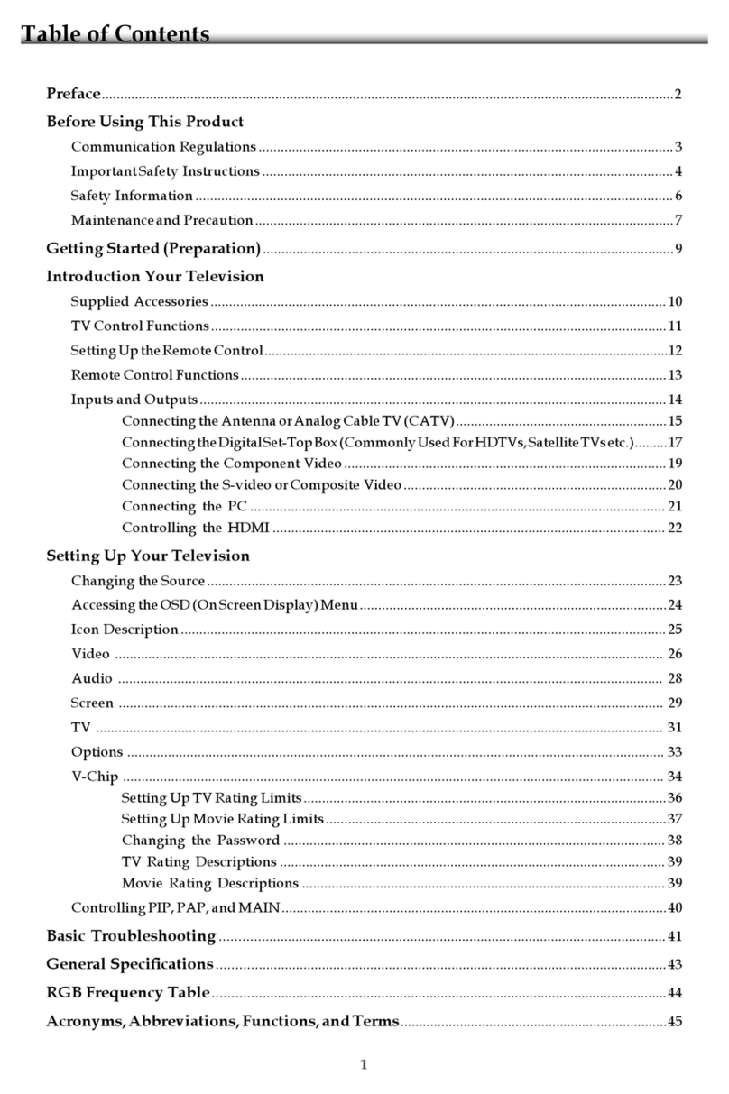
LG 42LH50 Series User manual

Order Number : GETEC-C1-09-018 FCC Class B Certification
Test Report Number : GETEC-E3-09-015 Page 1 / 1
EUT Type: LCD TV/Monitor
FCC ID.: BEJ47LH70UC
APPENDIX H
: USER’S MANUAL

Please read this manual carefully before operating
your set.
Retain it for future reference.
Record model number and serial number of the set.
See the label attached on the back cover and quote
this information to your dealer
when you require service.
LCD TV
OWNER’S MANUAL
42LH50
47LH50
32LH70
37LH70
42LH70
47LH70
P/NO : SAC33601904 (0901-REV00)
www.lgusa.com / www.lg.ca
This product qualifies for ENERGY STAR in the “factory
default (Home mode)” setting and this is the setting in which
power savings will be achieved.
Changing the factory default picture setting or enabling other
features will increase power consumption that could exceed
the limits necessary to quality for Energy Star rating.

2
WARNING / CAUTION
WARNING / CAUTION
To prevent fire or shock hazards, do not expose
this product to rain or moisture.
FCC NOTICE
Class B digital device
This equipment has been tested and found to comply
with the limits for a Class B digital device, pursuant to
Part 15 of the FCC Rules. These limits are designed
to provide reasonable protection against harmful
interference in a residential installation. This equipment
generates, uses and can radiate radio frequency energy
and, if not installed and used in accordance with the
instructions, may cause harmful interference to radio
communications. However, there is no guarantee that
interference will not occur in a particular installation.
If this equipment does cause harmful interference to
radio or television reception, which can be determined
by turning the equipment off and on, the user is
encouraged to try to correct the interference by one
or more of the following measures:
- Reorient or relocate the receiving antenna.
- Increase the separation between the equipment and
receiver.
- Connect the equipment to an outlet on a circuit
different from that to which the receiver is connected.
- Consult the dealer or an experienced radio/TV
technician for help.
Any changes or modifications not expressly approved
by the party responsible for compliance could void
the user’s authority to operate the equipment.
CAUTION
Do not attempt to modify this product in any way
without written authorization from LG Electronics.
Unauthorized modification could void the user’s
authority to operate this product
The lightning flash with arrowhead
symbol, within an equilateral triangle, is
intended to alert the user to the presence
of uninsulated “dangerous voltage” within the
product’s enclosure that may be of sufficient
magnitude to constitute a risk of electric shock to
persons.
The exclamation point within an equilateral
triangle is intended to alert the user to
the presence of important operating and
maintenance (servicing) instructions in the litera-
ture accompanying the appliance.
TO REDUCE THE RISK OF ELECTRIC SHOCK
DO NOT REMOVE COVER (OR BACK). NO
USER SERVICEABLE PARTS INSIDE. REFER TO
QUALIFIED SERVICE PERSONNEL.
WARNING/CAUTION
TO REDUCE THE RISK OF FIRE AND ELECTRIC
SHOCK, DO NOT EXPOSE THIS PRODUCT TO
RAIN OR MOISTURE.
NOTE TO CABLE/TV INSTALLER
This reminder is provided to call the CATV system
installer’s attention to Article 820-40 of the National
Electric Code (U.S.A.). The code provides guidelines for
proper grounding and, in particular, specifies that the
cable ground shall be connected to the grounding system
of the building, as close to the point of the cable entry
as practical.
PREPARATION
9
ACCESSORIES
PREPARATION
Ensure that the following accessories are included with your TV. If an accessory is missing, please contact the
dealer where you purchased the TV.
The accessories included may differ from the images below.
Option Extras
* Wipe spots on the exterior only with
the polishing cloth.
* Do not wipe roughly when removing
stain. Excessive pressure may cause
scratch or discoloration.
Polishing Cloth
(This feature is not available
for all models.)
Copyright© 2007 LGE,
All Rights Reserved.
D-sub 15 pin Cable
1.5V 1.5V
Owner’s Manual Power Cord
Remote Control,
Batteries
INPUT
FAV
MUTE
TV
STB
POWER
Q. MENU MENU
AV MODE
RETURN
ENTER
VOL CH
123
456
78
0
9
FLASHBK
P
A
G
E
DVD
VCR
CD Manual
When using the VGA (D-sub 15 pin
cable) PC connection, the user
must use shielded signal interface
cables with ferrite cores to maintain
standards compliance.
Cable management clip
(Refer to p.17)
Protection cover
(Refer to p.14)
bolts for stand assembly (Refer to p. 13)
Only 32/37/42/47LH7***
Stand rear cover
(Refer to p.15)
(37LH7*** only)
x 8
(42LH7*** only)
x 3 x 4
M4x20 M4x16
M4x20
(32LH7*** only)
x 7
M4x20
Protective Bracket and
Bolt for Power Cord
(Refer to P.18)
(Only 32/37/42/47LH7***)
(Only 37/42/47LH7***)
(47LH7*** only)
x 8
M4x16
Bolts for stand assembly
(Refer to p.12)
x 4
Only 37/42/47/55LH5***
Protection cover
(Refer to p.14)
1-screw for stand fixing
(Refer to p.15)
(Only 37/42LH5***, 32/37LH7***)

PREPARATION
10
FRONT PANEL INFORMATION
PREPARATION
■
Image shown may differ from your TV.
Only 32/37/42/47LH7***
ENTER
MENU
INPUT
CH
VOL
PROGRAMME
VOLUME
OK
MENU
INPUT
Intelligent Sensor
Adjusts picture according to
the surrounding conditions
POWER(Touch Sensor)
Power/Standby Indicator
• Illuminates red in standby mode.
• Illuminates White when the TV is switched on.
Note: You can adjust Power Indicator in the
OPTION menu.
Moving LED
Main Power Switch
Remote Control Sensor

PREPARATION
11
BACK PANEL INFORMATION
1
2
AUDIO IN
(RGB/DVI)
RGB IN
(PC)
RGB IN
COMPONENT IN
AUDIO
VIDEO
L/
L/
MONO
R
AUDIO
AUDIO
VIDEO
VIDEO
VARIABLE AUDIO OUT
VARIABLE AUDIO OUT
AV IN1 AV OUT
AV IN2
ANTENNA IN
RS-232C IN
(CONTROL)
2
57
1
Only 32/37/42/47LH7***
Power Cord Socket
For operation with AC power.
Caution: Never attempt to operate the TV on DC
power.
RGB/Audio Input
Connect the monitor output from a PC to the
appropriate input port.
Audio/Video Input
Connect audio/video output from an external
device to these jacks.
RS-232C IN (CONTROL) PORT
Used by third party devices.
Component Input
Connect a component video/audio device to
these jacks.
AV Output
Connect second TV or monitor to the AV OUT
socket on the TV.
Variable Audio Output
Connect an external amplifier or add a subwoofer
to your surround sound system.
Antenna Input
Connect RF antenna to this jack.
USB Input
Connect USB storage device to this jack.
HDMI Input
Connect a HDMI signal to HDMI IN.
Or DVI(VIDEO)signal to HDMI/DVI port with DVI
to HDMI cable.
1
2
3
4
6
7
8
4
3
6
1(DVI)
2
/DVI IN
3
8
9
5
9

PREPARATION
20
ANTENNA OR CABLE CONNECTION
PREPARATION
■To prevent damage do not connect to the power outlet until all connections are made between the devices.
1. Antenna (Analog or Digital)
Wall Antenna Socket or Outdoor Antenna without a Cable Box
Connections.
For optimum picture quality, adjust antenna direction if needed.
2. Cable
Wall
Antenna
Socket
Outdoor
Antenna
(VHF, UHF)
Cable TV
Wall Jack
Multi-family Dwellings/Apartments
(Connect to wall antenna socket)
RF Coaxial Wire (75 ohm)
Single-family Dwellings /Houses
(Connect to wall jack for outdoor antenna)
Be careful not to bend the bronze wire
when connecting the antenna.
Copper Wire
■To improve the picture quality in a poor signal area, please purchase a signal amplifier and install properly.
■If the antenna needs to be split for two TV’s, install a 2-Way Signal Splitter.
■If the antenna is not installed properly, contact your dealer for assistance.
ANTENNA/
CABLE IN
ANTENNA/
CABLE IN

EXTERNAL EQUIPMENT SETUP
21
EXTERNAL EQUIPMENT SETUP
HD RECEIVER SETUP
This TV can receive digital over-the-air/digital cable signals without an external digital set-top box. However, if
you do receive digital signals from a digital set-top box or other digital external device.
Component Connection
1. How to connect
Connect the video outputs (Y, PB, PR)of the digital set-
top box to the COMPONENT IN VIDEO 1 jacks on
the TV. Match the jack colors (Y = green, PB= blue, and
PR= red).
Connect the audio output of the digital set-top box to
the COMPONENT IN AUDIO 1 jacks on the TV.
2
1
2. How to use
■Turn on the digital set-top box.
(Refer to the owner’s manual for the digital set-top box. operation)
■Select the Component 1 input source on the TV using
the INPUT button on the remote control.
■If connected to COMPONENT IN2 input, select the
Component 2 input source on the TV.
■To prevent the equipment damage, never plug in any power cords until you have finished connecting all equipment.
■
Image shown may differ from your TV.
Y, CB/PB, CR/PR
Supported Resolutions
Horizontal Vertical
Frequency(KHz)Frequency(Hz)
15.73 59.94
15.73 60.00
31.47 59.94
31.47 60.00
44.96 59.94
45.00 60.00
33.72 59.94
33.75 60.00
26.97 23.94
27.00 24.00
33.71 29.97
33.75 30.00
67.432 59.94
67.50 60.00
Resolution
720x480i
720x480p
1280x720p
1920x1080i
1920x1080p
Signal
480i
480p
720p
1080 i
1080 p
Component
Yes
Yes
Yes
Yes
Yes
HDMI
No
Yes
Yes
Yes
Yes
1
2
COMPONENT IN
AUDIO
VIDEO
VAR
IVARIA
A
V
Y L RPBPR
12

EXTERNAL EQUIPMENT SETUP
22
EXTERNAL EQUIPMENT SETUP
HDMI Connection
Connect the digital set-top box to HDMI/DVI IN1,
2, 3, or 4 jack on the TV.
No separate audio connection is necessary.
HDMI supports both audio and video.
1. How to connect
2. How to use
■Turn on the digital set-top box.
(Refer to the owner’s manual for the digital set-top box.)
■Select the HDMI1, HDMI2, HDMI3, or HDMI4 input
source on the TV using the INPUT button on the remote
control.
2
1
HDMI-DTV
Horizontal Vertical
Frequency(KHz)Frequency(Hz)
31.47 59.94
31.50 60.00
44.96 59.94
45.00 60.00
33.72 59.94
33.75 60.00
26.97 23.94
27.00 24.00
33.71 29.97
33.75 30.00
67.432 59.939
67.50 60.00
Resolution
720x480p
1280x720p
1920x1080i
1920x1080p
1(DVI)
2
/DVI IN
3
HDMI OUTPUT
1

EXTERNAL EQUIPMENT SETUP
23
DVI to HDMI Connection
AUDIO IN
(RGB/DVI)
RGB IN
(PC)
RGB IN
1(DVI)
2
/DVI IN
3
L R
DVI OUTPUT AUDIO
1
2
GA DVI to HDMI cable or adapter is required for this con-
nection. DVI doesn't support audio, so a separate audio
connection is necessary.
NOTE
!
Connect the DVI output of the digital set-top box to
the HDMI/DVI IN 1, 2, 3, or 4jack on the TV.
Connect the digital set-top box audio output to the
AUDIO (RGB/DVI)jack on the TV.
1. How to connect
2. How to use
■Turn on the digital set-top box.
(Refer to the owner’s manual for the digital set-top box.)
■Select the HDMI1, HDMI2, HDMI3, or HDMI4 input
source on the TV using the INPUT button on the remote
control.
2
1

EXTERNAL EQUIPMENT SETUP
24
DVD SETUP
EXTERNAL EQUIPMENT SETUP
Component Connection
Component Input ports
To get better picture quality, connect a DVD player to the component input ports as shown below.
Component ports on the TV
YPBPR
Video output ports
on DVD player
Y
Y
Y
Y
PB
B-Y
Cb
Pb
PR
R-Y
Cr
Pr
Connect the video outputs (Y, PB, PR)of the DVD to the
COMPONENT IN VIDEO1 jacks on the TV.
Match the jack colors (Y = green, PB= blue, and PR= red).
Connect the audio outputs of the DVD to the
COMPONENT IN AUDIO1 jacks on the TV.
1. How to connect
2. How to use
■Turn on the DVD player, insert a DVD.
■Select the Component 1 input source on the TV using
the INPUT button on the remote control.
■If connected to COMPONENT IN 2 input, select the
Component 2 input source on the TV.
■Refer to the DVD player's manual for operating instructions.
2
1
1
2
COMPONENT IN
AUDIO
VIDEO
V
Y L RPBPR
1 2

EXTERNAL EQUIPMENT SETUP
25
Composite (RCA) Connection
AUDIO
L/
L/
MONO
MONO
AUDIO
AUDIO
VIDEO
VIDEO
VARIABLE AUDIO OUT
VARIABLE AUDIO OUT
AV IN1 AV OUT
AV IN2
RS-232C IN
(CONTROL)
R
L R
VIDEO
AUDIO
N
V
I)
12
HDMI Connection
1(DVI)
2
/DVI IN
3
HDMI OUTPUT
1
Connect the AUDIO/VIDEO jacks between TV and
DVD. Match the jack colors (Video = yellow, Audio Left
= white, and Audio Right = red)
1. How to connect
2. How to use
■Turn on the DVD player, insert a DVD.
■Select the AV1 or AV2 input source on the TV using the
INPUT button on the remote control.
■Refer to the DVD player's manual for operating instructions.
1
Connect the HDMI output of the DVD to the
HDMI/DVI IN1, 2, 3 or 4jack on the TV.
No separate audio connection is necessary.
HDMI supports both audio and video.
1. How to connect
2. How to use
■Select the HDMI1, HDMI2, HDMI3, or HDMI4 input
source on the TV using the INPUT button on the remote
control.
■Refer to the DVD player's manual for operating instructions.
2
1

EXTERNAL EQUIPMENT SETUP
26
VCR SETUP
EXTERNAL EQUIPMENT SETUP
Antenna Connection
■To avoid picture noise (interference), leave an adequate distance between the VCR and TV.
Connect the RF antenna out socket of the
VCR to the ANTENNA/CABLE IN sock-
et on the TV.
Connect the antenna cable to the RF
antenna in socket of the VCR.
1. How to connect
2. How to use
■Set VCR output switch to 3 or 4 and then
tune TV to the same channel number.
■Insert a video tape into the VCR and press
PLAY on the VCR. (Refer to the VCR owner’s
manual.)
2
1
ANTENNA INANTENNA IN
L R
S-VIDEO VIDEO
OUTPUT
SWITCH
ANT IN
ANT OUT
AUDIO
Wall Jack
Antenna
1
2

EXTERNAL EQUIPMENT SETUP
27
Composite (RCA) Connection
GIf you have a mono VCR, connect the audio cable from
the VCR to the AUDIO L/MONO jack of the TV.
NOTE
!
P
C)
GB
IN
AUDIO
D
EO
L/MONO
AUDIO
AUDIO
VIDEO
VIDEO
VARIABLE AUDIO OUT
VARIABLE AUDIO OUT
AV IN1 AV OUT
AV IN2
RS-23
2
(CON
T
R
AUDIO IN
(RGB/DVI)
L R
S-VIDEO VIDEO
AUDIO
OUTPUT
SWITCH
ANT IN
ANT OUT
1
Connect the AUDIO/VIDEO jacks between TV and
VCR. Match the jack colors (Video = yellow, Audio Left
= white, and Audio Right = red)
1. How to connect
2. How to use
■Insert a video tape into the VCR and press PLAY on the VCR.
(Refer to the VCR owner’s manual.)
■Select the AV1 input source on the TV using the INPUT
button on the remote control.
■If connected to AV IN2, select AV2 input source on the TV.
1

EXTERNAL EQUIPMENT SETUP
28
OTHER A/V SOURCE SETUP
EXTERNAL EQUIPMENT SETUP
L R
VIDEO
C
)
GB
IN
AUDIO
D
EO
L/
L/
MONO
MONO
AUDIO
AUDIO
VIDEO
VIDEO
VARIABLE AUDIO OUT
VARIABLE AUDIO OUT
AV IN1 AV OUT
AV IN2
ANT
EANTE
RS-232C IN
(CONTROL)
R
AUDIO IN
(RGB/DVI)
Camcorder
Video Game Set
Connect the AUDIO/VIDEO jacks
between TV and external equipment.
Match the jack colors
.
(Video = yellow, Audio Left = white, and
Audio Right = red)
1. How to connect
2. How to use
■Select the AV2 input source on the TV using
the INPUT button on the remote control.
■If connected to AV IN1 input, select the AV1
input source on the TV.
■Operate the corresponding external equipment.
1
1

EXTERNAL EQUIPMENT SETUP
29
PC SETUP
This TV provides Plug and Play capability, meaning that the PC adjusts automatically to the TV's settings.
VGA (D-Sub 15 pin) Connection
RS-232C IN
(
CONTROL&SERVICE)
OPTICAL DIGITAL
AUDIO OUT
ANTENNA/
CABLE IN
2
3
1
R
/DVI IN
AUDIO IN
(RGB/DVI)
RGB IN (PC)
RGB OUTPUT
AUDIO
12
Connect the VGA output of the PC to the RGB IN
(P C)jack on the TV.
Connect the PC audio output to the AUDIO IN
(RGB/DVI)jack on the TV.
1. How to connect
2. How to use
■Turn on the PC and the TV.
■Select the RGB-PC input source on the TV using the
INPUT button on the remote control.
2
1

EXTERNAL EQUIPMENT SETUP
30
EXTERNAL EQUIPMENT SETUP
GTo get the the best picture quality, adjust the PC
graphics card to 1920x1080.
GDepending on the graphics card, DOS mode may
not work if a HDMI to DVI Cable is in use.
GIn PC mode, there may be noise associated with
the resolution, vertical pattern, contrast or bright-
ness. If noise is present, change the PC output to
another resolution, change the refresh rate to
another rate or adjust the brightness and contrast
on the PICTURE menu until the picture is clear.
GAvoid keeping a fixed image on the screen for a
long period of time. The fixed image may become
permanently imprinted on the screen.
GThe synchronization input form for Horizontal and
Vertical frequencies is separate.
GDepending on the graphics card, some resolution
settings may not allow the image to be positioned
on the screen properly.
GIf there are overscan in HDMI-PC 1920x1080,
change aspect ratio to Just scan.
NOTES
!
DVI to HDMI Connection
O
AUDIO
L R
RS-232C IN
(
CONTROL&SERVICE)
OP
A
A
C
RGB IN (PC)
AV IN 1
MPONENT IN
MONO
( )
AUDIOVIDEO L R
AUDIO IN
(RGB/DVI)
2
3
1
/DVI IN
AUDIO
DVI OUTPUT
12
Connect the DVI output of the PC to the HDMI/DVI
IN1, 2, 3, or 4jack on the TV.
Connect the PC audio output to the AUDIO IN
(RGB/DVI) jack on the TV.
1. How to connect
2. How to use
■Turn on the PC and the TV.
■Select the HDMI1, HDMI2, HDMI3, or HDMI4 input
source on the TV using the INPUT button on the remote
control.
2
1

EXTERNAL EQUIPMENT SETUP
31
Resolution
HDMI-DTV mode
Horizontal Vertical
Frequency(kHz) Frequency(Hz)
31.468 70.09
31.469 70.08
31.469 59.94
35.15 56.25
37.87 60.31
48.36 60.00
56.47 70.06
47.77 59.87
47.71 60.01
63.98 60.02
67.50 60.00
Resolution
RGB-PC mode
Horizontal Vertical
Frequency(kHz) Frequency(Hz)
31.468 70.09
31.469 70.08
31.469 59.94
35.156 56.25
37.879 60.31
48.363 60.00
56.476 70.06
47.776 59.87
47.712 60.015
63.981 60.02
75.00 60.00
66.587 59.934
640x350
720x400
640x480
800x600
1024x768
1280x768
1360x768
1280x1024
1600x1200
1920x1080
640x350
720x400
640x480
800x600
1024x768
1280x768
1360x768
1280x1024
1920x1080p

EXTERNAL EQUIPMENT SETUP
32
EXTERNAL EQUIPMENT SETUP
Screen Setup for PC mode
Selecting Resolution
You can choose the resolution in RGB-PC mode.
The Position, Phase, and Size can also be adjusted.
Select PICTURE.
Select Screen (RGB-PC).
Select Resolution.
Select the desired resolution.
1024 x 768
1280 x 768
1360 x 768
1366 x 768
Auto config.
Resolution
G
Position
Size
Phase
Reset
SCREEN
Move
Prev.
1
MENU
3
4
2
ENTER
ENTER
ENTER
5
ENTER
Enter
Move
PICTURE
E
RG
• Contrast 100
• Brightness 50
• Sharpness 70
• Color 70
• Tint 0
• Advanced Control
• Picture Reset
Screen (RGB-PC)

EXTERNAL EQUIPMENT SETUP
33
Auto Configure
Automatically adjusts picture position and minimizes image instability. After adjustment, if the image is still
not correct, try using the manual settings or a different resolution or refresh rate on the PC.
Select Screen (RGB-PC).
Select Auto config..
Auto config. G
Resolution
Position
Size
Phase
Reset
SCREEN
Move
Prev.
To Set
3
2
ENTER
ENTER
Select Yes.
4
ENTER
Start Auto Configuration.
5
ENTER
Select PICTURE.
1
MENU
• If the position of the image is still not
correct, try Auto adjustment again.
• If picture needs to be adjusted again
after Auto adjustment in RGB-PC, you
can adjust the P os it ion, Size or
Phase.
Yes No
Enter
Move
PICTURE
E
RG
• Contrast 100
• Brightness 50
• Sharpness 70
• Color 70
• Tint 0
• Advanced Control
• Picture Reset
Screen (RGB-PC)
Other manuals for 42LH50 Series
7
This manual suits for next models
21
Table of contents
Other LG LCD TV manuals