LG 49UF640 SERIES User manual

CHASSIS : LD59R / LD5ZRCHASSIS : LD59R / LD5ZR
MODEL : 43/49UF640*MODEL : 43/49UF640*
43/49UF640*-ZA43/49UF640*-ZA
CAUTIONCAUTION
BEFORE SERVICING THE CHASSIS,BEFORE SERVICING THE CHASSIS,
READ THE SAFETY PRECAUTIONS IN THIS MANUAL.READ THE SAFETY PRECAUTIONS IN THIS MANUAL.
LED TVLED TV
SERVICE MANUALSERVICE MANUAL
North/Latin North/Latin
America America
http://aic.lgservice.comhttp://aic.lgservice.com
Europe/Africa http://eic.lgservice.comEurope/Africa http://eic.lgservice.com
Asia/Oceania Asia/Oceania
http://biz.lgservice.comhttp://biz.lgservice.com
Internal Use OnlyInternal Use Only


CONTENTSCONTENTS
CONTENCONTEN
TS TS
..................................
......................................
......................................
......................................
.................... ....................
22
SAFETY PRECASAFETY PRECA
UTIONS UTIONS
......................................
........................................
......................................
.............. ..............
33
SERVISERVI
CING CING
PRECAUTPRECAUT
IONS IONS
....................................
........................................
......................................
........... ...........
44
SPECIFICSPECIFIC
AA
TION TION
......................................
......................................
........................................
......................................
.......... ..........
66
ADJUSTMEADJUSTME
NT NT
INSTRUCTINSTRUCT
ION ..............................ION ..............................
......................................
............. .............
1515
BLOCK DIAGRAMBLOCK DIAGRAM
......................................
......................................
......................................
........................................
..... .....
2121
EXPLODEEXPLODE
D D
VIEW VIEW
......................................
......................................
......................................
........................................
..... .....
3030
SCHEMATIC CIRCUIT DIAGRAM ........................................... APPENDIXSCHEMATIC CIRCUIT DIAGRAM ........................................... APPENDIX
TROUBLTROUBL
E E
SHOOTING GUIDE SHOOTING GUIDE
..................................
......................................
............ ............
APPENDIAPPENDI
XX

Many elMany el
ectrical ectrical
and mechanicand mechanic
al parts al parts
in this in this
chassis chassis
have spechave spec
ial safetyial safety
-related -related
characteristics. characteristics.
These These
parts arparts ar
e identifiee identifie
d by d by
in thein the
Schematic Diagram and Schematic Diagram and
Exploded View.Exploded View.
It is essential that these special safety parts should be replaced with the same components as recommended in this manual to preventIt is essential that these special safety parts should be replaced with the same components as recommended in this manual to prevent
Shock, Fire, or other Hazards.Shock, Fire, or other Hazards.
Do not modify the original design Do not modify the original design
without permission of manufacturer.without permission of manufacturer.
General GuidanceGeneral Guidance
AnAn
isolation Transformer should always be usedisolation Transformer should always be used
during the during the
servicing of a receiver whose chassis is not isolated from the ACservicing of a receiver whose chassis is not isolated from the AC
power line. Use a transformer of adequate power rating as thispower line. Use a transformer of adequate power rating as this
protects the technician from accidents resulting in personal injuryprotects the technician from accidents resulting in personal injury
from electrical shocks.from electrical shocks.
It will also protect the receiver and it's components from beingIt will also protect the receiver and it's components from being
damaged by accidental shorts of the circuitry that may bedamaged by accidental shorts of the circuitry that may be
inadvertently introduced during the inadvertently introduced during the
service operation.service operation.
If any fuse (or Fusible Resistor) in this TV receiver is blown,If any fuse (or Fusible Resistor) in this TV receiver is blown,
replace it with the specified.replace it with the specified.
When replacing a high When replacing a high
wattage resistor (Oxide Metal Film Resistor,wattage resistor (Oxide Metal Film Resistor,
over 1 W), keep the over 1 W), keep the
resistor 10 mm away from PCB.resistor 10 mm away from PCB.
Keep wires away from high voltage or Keep wires away from high voltage or
high temperature parts.high temperature parts.
Before returning the receiver to the Before returning the receiver to the
customer,customer,
always perform analways perform an
AC leakage current checkAC leakage current check
on the exposedon the exposed
metallic parts of the cabinet, such as antennas, terminals, etc., tometallic parts of the cabinet, such as antennas, terminals, etc., to
be sure the set is safe to operate without damage of electricalbe sure the set is safe to operate without damage of electrical
Leakage Current Hot CheckLeakage Current Hot Check
(See below Figure)(See below Figure)
Plug the AC cord directly into the AC outlet.Plug the AC cord directly into the AC outlet.
Do not use a Do not use a
line Isolation Transformline Isolation Transform
er during this check.er during this check.
Connect 1.5 K / 10 watt resistor in parallel with a 0.15 uF capacitorConnect 1.5 K / 10 watt resistor in parallel with a 0.15 uF capacitor
between a known good earth ground (Water Pipe, Conduit, etc.)between a known good earth ground (Water Pipe, Conduit, etc.)
and the exposed metallic parts.and the exposed metallic parts.
Measure the AC voltage across the resistor using AC voltmeterMeasure the AC voltage across the resistor using AC voltmeter
with 1000 ohms/volt with 1000 ohms/volt
or more sensitivity.or more sensitivity.
Reverse plug the AC cord into Reverse plug the AC cord into
the AC outlet and repeat AC voltagethe AC outlet and repeat AC voltage
measurements for each exposed metallic part. Any voltagemeasurements for each exposed metallic part. Any voltage
measured must not exceed 0.75 volt RMS which is corresponds tomeasured must not exceed 0.75 volt RMS which is corresponds to
0.5 mA.0.5 mA.
In case any measurement is out of the limits specified, there isIn case any measurement is out of the limits specified, there is
possibility of shock hazard and the set must be checked andpossibility of shock hazard and the set must be checked and
repaired before it is returned to repaired before it is returned to
the customer.the customer.
Leakage Current Hot Check circuitLeakage Current Hot Check circuit
IMPORTANT SAFETY NOTICEIMPORTANT SAFETY NOTICE
SAFETY PRECAUTIONSSAFETY PRECAUTIONS

SERVICING PRECAUTIONS
CAUTION: Before servicing receivers covered by this service
manual and its supplements and addenda, read and follow the
SAFETY PRECAUTIONS
on page 3 of this publication.
NOTE
: If unforeseen circumstances create conict between
the
following servicing precautions and any of the safety precautions
on page 3 of this publication, always follow the safety precau-
tions. Remember: Safety First.
General Servicing Precautions
1. Always unplug the receiver AC power cord from the AC power
source before;
a. Removing or reinstalling any component, circuit board
module or any other receiver assembly.
b. Disconnecting or reconnecting any receiver electrical plug
or other electrical connection.
c. Connecting a test substitute in parallel with an electrolytic
capacitor in the receiver.
CAUTION
: A wrong part substitution or incorrect polarity
installation of electrolytic capacitors may result in an explo-
sion hazard.
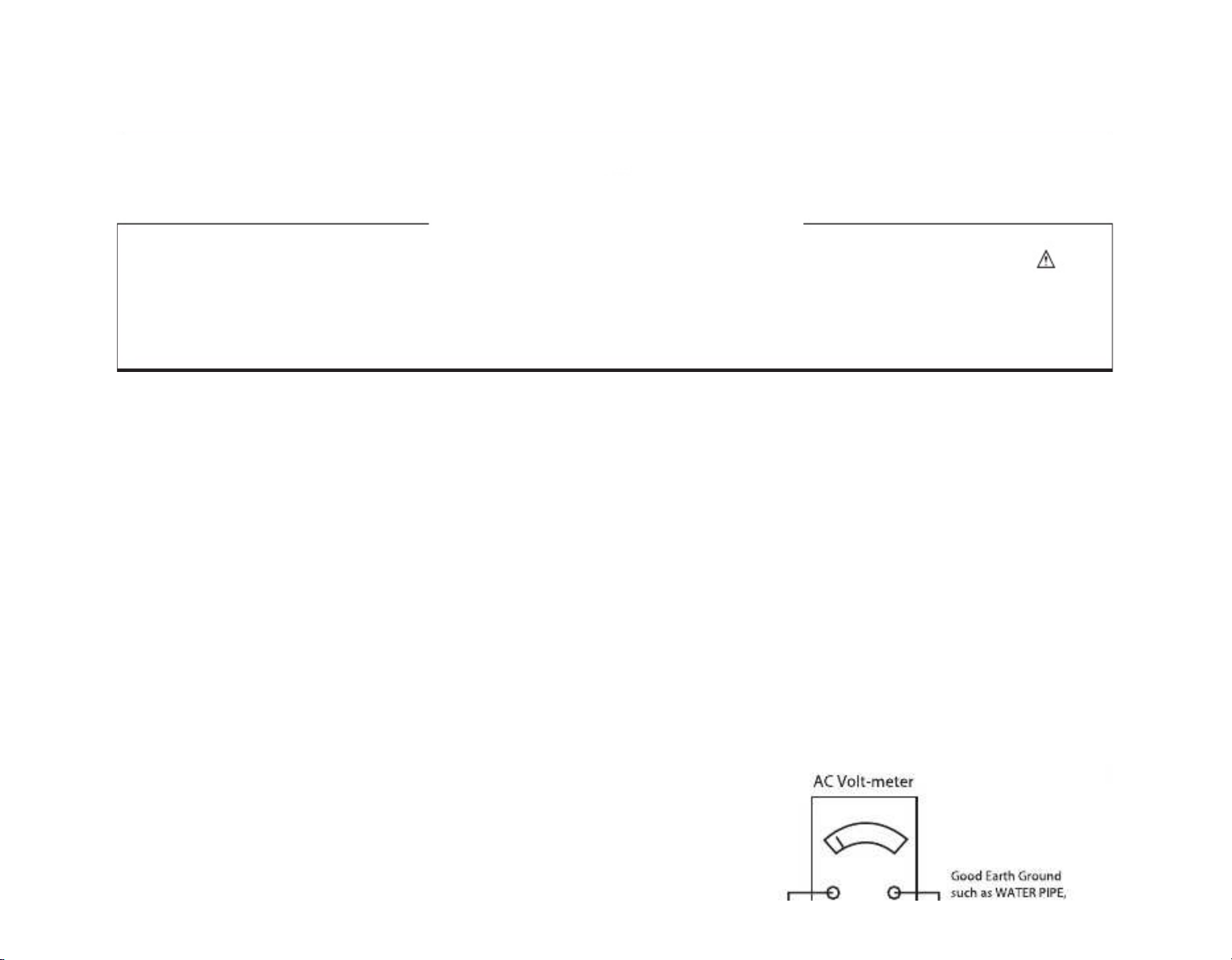
2. Test high voltage only by measuring it with an appropriate
high voltage meter or other voltage measuring device (DVM,
FETVOM, etc) equipped with a suitable high voltage probe.
Do not test high voltage by "drawing an arc".
3. Do not spray chemicals on or near this receiver or any of its
assemblies.
4. Unless specied otherwise in this service manual, clean
electrical contacts only by applying the following mixture to the
contacts with a pipe cleaner, cotton-tipped stick or comparable
non-abrasive applicator; 10 % (by volume) Acetone and 90 %
(by volume) isopropyl alcohol (90 % - 99 % strength)
CAUTION
: This is a ammable mixture.
Unless specied otherwise in this
service manual, lubrication
of contacts in not required.
5. Do not defeat any plug/socket B+ voltage interlocks with which
receivers covered by this service manual might be equipped.
6. Do not apply AC power to this instrument and/or any of its
2. After removing an electrical assembly equipped with ES
devices, place the assembly on a conductive surface such as
aluminum foil, to prevent electrostatic charge buildup or expo-
sure of the assembly.
3. Use only a grounded-tip soldering iron to solder or unsolder
ES devices.
4. Use only an anti-static type solder removal device. Some sol-
der removal devices not classied as “anti-static” can generate
electrical charges sufcient to damage ES devices.
5. Do not use freon-propelled chemicals. These can generate
electrical charges sufcient to damage ES devices.
6. Do not remove a replacement ES device from its protective
package until immediately before you are ready to install it.
(Most replacement ES devices are packaged with leads elec-
trically shorted together by conductive foam, aluminum foil or
comparable conductive material).
7. Immediately before removing the protective material from the
leads of a replacement ES device, touch the protective mate-
rial to the chassis or circuit assembly into which the device will
be installed.
CAUTION
: Be sure no power is applied to the chassis or cir-
cuit, and observe all other safety precautions.
8. Minimize bodily motions when handling unpackaged replace-
ment ES devices. (Otherwise harmless motion such as the
brushing together of
your clothes fabric or
the lifting
of your
foot from a carpeted oor can generate static electricity suf
-
cient to damage an ES device.)
General Soldering Guidelines
1. Use a grounded-tip, low-wattage soldering iron and appropri-
ate tip size and shape that will maintain tip temperature within
the range or 500 °F to 600 °F.
2. Use an appropriate gauge of RMA resin-core solder composed
of 60 parts tin/40 parts lead.
3. Keep the soldering iron tip clean and well tinned.
4. Thoroughly clean the surfaces to be soldered. Use a mall wire-
bristle (0.5 inch, or 1.25 cm) brush with a metal handle.
This manual suits for next models
3
Table of contents
Other LG LED TV manuals