-8-
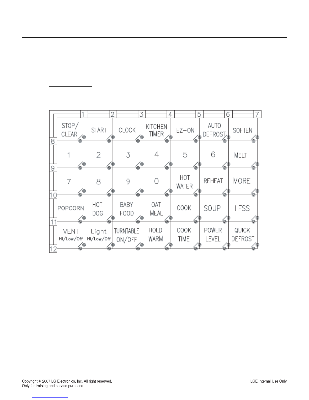
4-2. Explanation of Control Panel
1. DISPLAY The Display includes a clock and
indicators to tell you time of day, cooking time
settings and cooking unctions selected.
2. POPCORN Touch this pad when popping popcorn
in your microwave oven.
3. POTATO Touch this pad when roasting potato in
your microwave oven.
4. PIZZA Touch this pad when roasting pizza in your
microwave oven.
5. FROZEN ENTREE Touch this pad to select
frozen entree.
6. AUTO COOK Touch this pad to cook fresh
vegetable, frozen vegetable, rice, or casseroles.
7. AUTO REHEAT Touch this pad to reheat dinner
plate, soup/sauce, casserole, roll/muffin.
8. SOFTEN Touch this pad to soften butter, ice
cream, cream cheese, frozen juice.
9. MELT Touch this pad to melt butter or margarine,
chocolate, cheese, marshmallow.
10. AUTO DEFROST Meat, poultry, fish. Touch this
pad to select food type and defrost food by
weight.
11. TIME DEFROST This pad provides you with the
RAPID defrosting method for 1.0 pound frozen
foods.
12. TIME Touch this pad to set a cooking time.
13. CLOCK Touch this pad to enter the time of day.
14. POWER LEVEL Touch this pad to select a
cooking power level.
15. NUMBER Touch number pads to enter cooking
time, power level, quantities or weights.
16. START/ENTER Touch this pad to start a
function. If you open the door after oven begins
to cook, retouch START/ENTER.
17. STOP/CLEAR Touch this pad to stop the oven
or clear all entries.
18. LIGHT ON/OFF Touch this pad to turn the
cooktop/countertop light on or off.
19. VENT HI/LOW/OFF Touch this pad to turn the
Vent on or off.
20. ADD 30 SEC Touch this pad to control the add
30sec. cook time.


M Service manual")


