LG STUDIOWORKS User manual

SERVICE MANUAL
LG STUDIOWORKS 77M
MODEL

1. PICTURE TUBE
Size : 17 inch (Flat Square Tube)
Gun : In-line
DefIection Angle : 90°
Neck Diameter : 29.1 mm
Dot Pitch : 0.27 mm
2. SIGNAL
2-1. Horizontal & Vertical Sync
1) Input Voltage Level: Low=0~0.8V, High=2.5~5.5V
2) Sync Polarity : Positive or Negative
2-2. Video Input SIignal
1) Voltage Level : 0~0.7 Vp-p
a) Color 0, 0 : 0 Vp-p
b) Color 7, 0 : 0.467 Vp-p
c) Color 15, 0 : 0.7 Vp-p
2) Input Impedance : 75 Ω
3) Video Color : R, G, B Analog
4) Signal Format : Refer to the Timing Chart
2-3. Signal Connector
15 Pin D-Sub Connector
2-4. Operating Frequency
Horizontal : 30 ~ 70 kHz
Vertical : 50 ~ 160 Hz
3. STEREO AUDIO
3-1. Input Voltage : 0.707 Vrms
3-2. Input Impedance : 20kΩmin
3-3. Amp Output : 2W+2W rms
3-4. Speaker Impedance : 4Ω
3-5. Speaker Type : Dome, Bassreflex, Closed
.
4. POWER SUPPLY
4-1. Power Range
AC 100V~240V (Free Voltage), 50/60Hz, 2.3A Max.
4-2. Power Consumption
5. DISPLAY AREA
5-1. Active Video Area : 310 x 230 mm (12.20" x 9.06")
5-2. Display Color : Full Colors
5-3. Display Resolution : 1024 Dots x 768 Lines/85Hz
1280 Dots x 1024 Lines/60Hz
5-4. Video Bandwidth : 110 MHz
6. ENVIRONMENT
6-1. Operating Temperature: 15°C~30°C (59°F~86°F)
(Ambient)
6-2. Relative Humidity : 8%~80%
(Non-condensing)
6-3. Altitude : 5,000m
7. DIMENSIONS (With TILT/SWIVEL)
Width : 465.0 mm (18.31")
Depth : 442.0 mm (17.40")
Height : 435.5 mm (17.15")
8. WEIGHT (WithTILT/SWIVEL)
Net. Weight : 19.0 kg (41.89 lbs)
Gross Weight : 23.0 kg (50.71 lbs)
SPECIFICATIONS
- 2 -
MODE
NORMAL (ON)
STAND-BY
SUSPEND
OFF
H/V SYNC
ON/ON
OFF/ON
ON/OFF
OFF/OFF
POWER CONSUMPTION
less than 120W
less than 15W
less than 15W
less than 8W
LED COLOR
GREEN
ORANGE
ORANGE

CONTROL LOCATIONS
- 10 -
MAIN
VIDEO
8
9
10
7
123
456
SW201 VR201 VR202 SW206 SW205
SW204 SW203
SW202
CONTROL
EARPHONE JACK
MIC JACK
MIC OUT AUDIO IN
AUDIO
SPEAKER SPEAKER
FBT
VR701
VR901
Ref. No.
SW201
VR201
VR202
SW206
SW205
Control Function
POWER SWITCH
CONTRAST CONTROL
BRIGHTNESS CONTROL
SOUND MUTE
SOUND
No.
1
2
3
4
5
No.
6
7
8
9
10
Ref. No.
SW202
SW204
SW203
VR701
VR901
Control Function
ENTER BUTTON
OSD SELECT RIGHT
OSD SELECT LEFT
H/V ADJUSTMENT
B+ADJUSTMENT

ADJUSTMENT
- 17 -
GENERAL INFORMATION
All adjustment are thoroughly checked and corrected
when the monitor leaves the factory, but sometimes
several minor adjustment may be required.
Adjustment should be following procedure and after
warming up for a minimum of 30 minutes.
• Alignment appliances and tools.
- IBM compatible PC.
- Programmable Signal Generator.
(eg. VG-819 made by Astrodesign Co.)
- E(E)PROM with each mode data saved.
- Alignment Adaptor and Software.
- Digital Voltmeter.
- White Balance Meter.
- Luminance Meter.
- High-voltage Meter.
AUTOMATIC AND MANUAL DEGAUSSING
The degaussing coil is mounted around the CRT so that
automatic degaussing when turn on the monitor. But a
monitor is moved or faced in a different direction, become
poor color purity cause of CRT magnetized, then press
(DEGAUSSING) on the OSD menu.
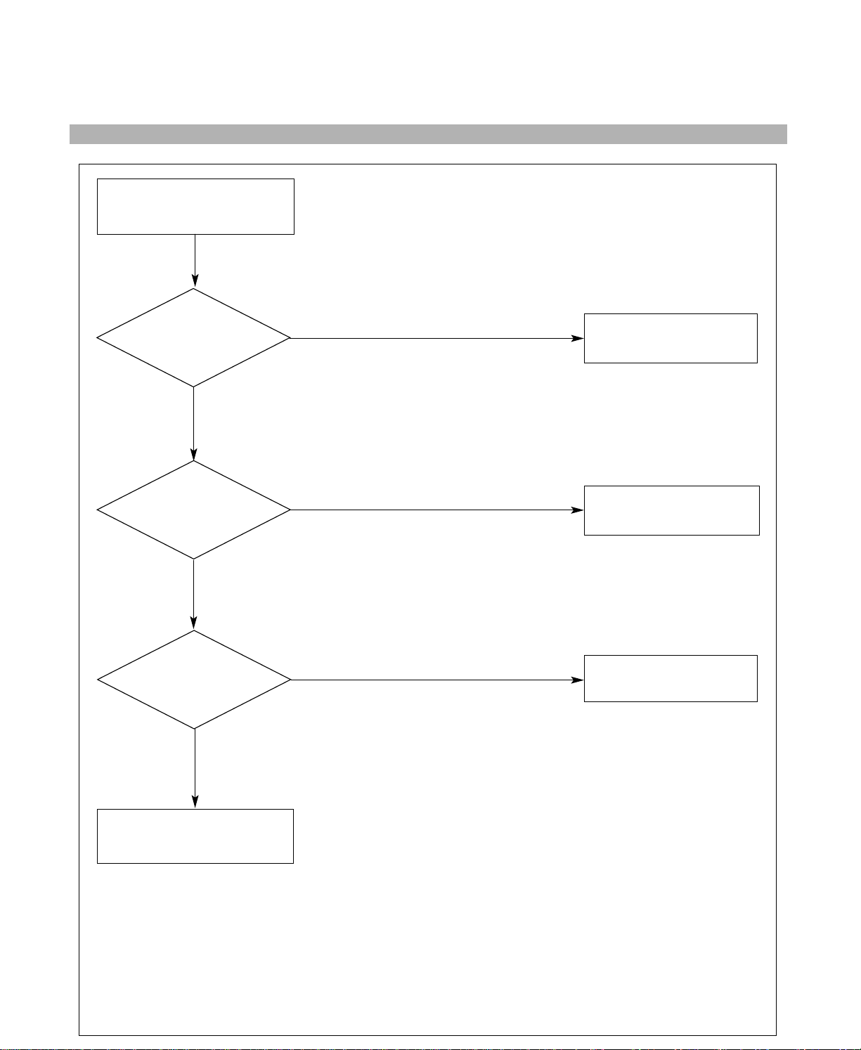
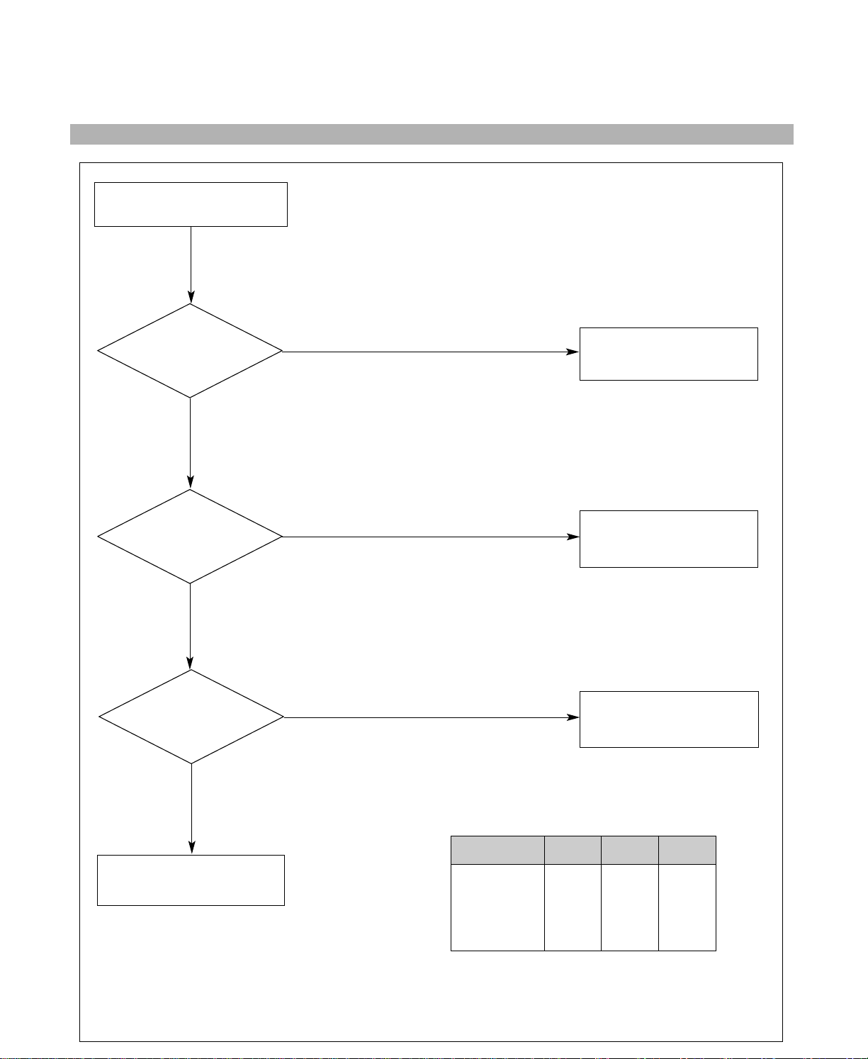
ADJUSTMENT PROCEDURE & METHOD
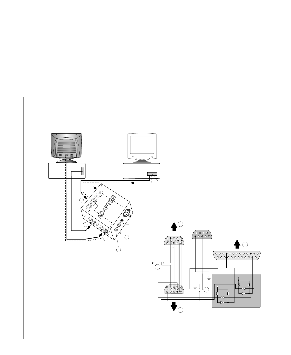
-Install the cable for adjustment such as Figure 1 and run
the alignment program on the DOS for IBM compatible PC.
-Set external Brightness and Contrast volume to max position.
1. Adjustment for B+ Voltage.
1) Display cross hatch pattern at Mode 4.
2) Adjust C951 + voltage to 160±0.5Vdc with VR901.
2. Adjustment for High-Voltage.
1) Display cross hatch pattern at Mode 4.
2) Adjust FBT Anode voltage to 141±0.5Vdc with
VR701.
5. Adjustment for Factory Mode (Preset Mode).
1) Display cross hatch pattern at Mode 1.
2) Run alignment program for MB776B on the IBM
compatible PC.
3) COMMAND →START →Y(Yes) command.
4) DIST. ADJ. →TILT command.
5) Adjust tilt as arrow keys to be the best condition.
6) DIST. ADJ. →BALANCE command.
7) Adjust balance of side-pincushion as arrow keys to
be the best condition.
8) DIST. ADJ. →FOS. ADJ →Mode No. →1 command.
9) Adjust V-SIZE as arrow keys to 230±2mm.
10)
Adjust V-POSITION as arrow keys to center of the
screen.
11)
Adjust H-SIZE as arrow keys to 310±2mm.
12)
Adjust H-POSITION as arrow keys to center of the
screen.
13)
Adjust S-PCC (Side-Pincushion) as arrow keys to
be the best condition.
14)
Adjust TRAPEZOID as arrow keys to be the best
condition.
15)
Display from Mode 2 to Mode 7 and repeat above
from number 9) to 14).
16)
PRESET EXIT → Y(Yes) command.
6. Adjustment for White Balance and Luminance.
1) Set the White Balance Meter.
2) Press the (DEGAUSSING) on the OSD menu for
demagnetization of the CRT.
3) Display color 0,0 pattern at Mode 4.
4) COLOR ADJ. → LUMINANCE command of the
alignment program.
5) Set Brightness and Sub-Brightness to max position.
6) COLOR ADJ. → BIAS ADJ. → COLOR NO. → 1
command of the alignment program.
7) Check whether blue color or not at R-BIAS and G-
BIAS to min position and adjust B-BIAS to
0.3±0.05FL of the raster luminance.
8) Adjust R-BIAS and G-BIAS command to
x=0.281±0.01 and y=0.311±0.01 on the White
Balance Meter with PC arrow keys.
9) Adjust SUB-BRIGHT command to 0.4±0.1FL of the
raster luminance.
10)
Display color 15,0 box pattern (70x70mm) at Mode4.
11)
DRIVE ADJ → No 1. command.
12)
Set Contrast and Sub-Contrast to max position.
13)
Set B-DRIVE to 2/3 150(96 decimal) position at
DRIVE of the alignment program.
14)
Adjust R-DRIVE and G-DRIVE command to white
balance x=0.283±0.001 and y=0.298±0.001 on the
White Balance Meter with PC arrow keys.
15)
Adjust Sub-Contrast command to 54±2FL(MPR),
46±2FL(TCO) of the raster luminance.
16)
Save in COLOR 1.

- 18 -
Figure 1. Cable Connection
220
Monitor to be
adjusted
VIDEO
SIGNAL GENERATOR
IBM
Compatible PC
PARALLEL PORT
Power inlet (required)
Power LED
ST Switch
Power Select Switch
(110V/220V)
Control Line
Not used
RS232C
PARALLEL
V-SYNC POWER
ST
VGS MONITOR
E
E
V-Sync On/Off Switch
(Switch must be ON.)
F
F
AA
B
B
C
C
1510
5
569
1
1
1
14
13
25
6
5V
5V
5V
4.7K
4.7K
4.7K
74LS06
74LS06
OFF ON
OFF
ON
11
17)
Display color 15,0 full white patten at Mode 4.
18)
COLOR ADJ. → LUMINANCE → ABL command.
19)
Adjust ABL to 35±1FL(MPR), 30±1(TCO) of the
luminance.
20)
Exit from the program.
* Note : Color mode 2 data is automatically save in
the EEPROM by the microprocessor.
7. Adjustment for Focus.
1) Display H character in full screen at Mode 4.
2) Adjust two Focus control on the FBT that focus
should be the best condition.

TROUBLESHOOTING GUIDE
- 19 -
NO POWER
(POWER INDICATOR OFF)
TROUBLE IN
D901, D902, D903, D904
TROUBLE IN FUSE
(F901)
TROUBLE IN
IC901, IC902
TROUBLE IN
D920, D922, D923,
D924, D926
TROUBLE IN
IC923, IC925, Q922,
Q923, Q924, Q926
CHECK
FUSE OK?
CHECK
C907 VOLTAGE?
(AC120V: 170VDC,
AC220V: 310VDC)
NO
YES
YES
YES
YES
NO
NO
NO
CHECK
IC901 PIN 3
WAVEFORM
(SQUARE WAVE
COMES OUT?)
CHECK
D920, D922, D924,
D923, D926
VOLTAGE?
1. NO POWER

- 20 -
2. NO CHARACTER
NO CHARACTER
CHECK
IC302 PIN 7, 15, 18,
21(8V) ?
CHECK
IC302 PIN 6, 8, 10 ?
CHECK
IC302 PIN 16, 19, 22 ?
CHECK
IC303
PIN 1, 3, 5 ?
CHECK
IC303 PIN 6 (70V)
10 (12V) ?
TROUBLE IN
P302 12V LINE, IC304
TROUBLE IN
PC SIGNAL,
P301 SIGNAL CABLE
TROUBLE IN
IC302
TROUBLE IN
P302 12V LINE/70V LINE
TROUBLE IN IC303
NO
YES
NO
NO
YES
YES
YES
YES
NO
NO
CHECK
R, G, B CATHODE
VOLTAGE?
TROUBLE IN
R338~R341,
R344, R345, L302~L304,
D307~D310, D312, D313
TROUBLE IN
CRT SOCKET
YES
NO

- 21 -
NO VIDEO
(POWER INDICATOR ON)
CHECK
POWER INDICATOR
GREEN or ORANGE?
CHECK
D712 ANODE
(-120V)?
CHECK
G1VOLTAGE?
(-10~20V)
TROUBLE IN
D712
TROUBLE IN
D926, Q925 (6.3V)
TROUBLE IN
Q801~Q806
DPM MODE
(NO H and/or V SYNC)
ORANGE
NO
GREEN
YES
YES
NO
3. NO RASTER

- 22 -
4. NO HORIZONTAL DEFLECTION
NO H-DEFLECTION
(ONE VERTICAL LINE)
CHECK
Q706?
CHECK
B+ VOLTAGE
(160V)?
CHECK
T701(FBT) PIN 3
(31KHZ 70V,
69KHZ 140V) ?
CHECK
Q705 COLLECTOR
WAVEFORM?
TROUBLE IN
Q706
TROUBLE IN
160V LINE
TROUBLE IN
Q717, Q718, Q719,
D707
TROUBLE IN
Q705
TROUBLE IN
T701, P701
NO
NO
YES
YES
YES
YES
NO
NO

- 23 -
5. TROUBLE IN H-LINEARITY
UNBALANCED OF H-LIN.
CHECK
IC401
PIN 18, 19, 20?
CHECK
Q711~Q716?
CHECK
L703?
TROUBLE IN
IC401 (MICOM)
TROUBLE IN
Q711 ~ Q716
TROUBLE IN
L703
TROUBLE IN
L720, R744
NO
NO
NO
YES
YES
YES Cs SIGNAL TABLE
HORIZONTAK
FREQUENCY(fH)
30K ~ 39K
39K ~ 47.5K
47.5K ~ 62K
62K ~ 70K
Cs0
L
L
L
H
Cs1
L
L
H
H
Cs2
L
H
H
H

- 24 -
6. NO VERTICAL DEFLECTION
NO V-DEFLECTION
(ONE HORIZONTAL LINE)
CHECK
IC601 PIN 3
(15V)?
CHECK
IC601 PIN 7
(40V)?
CHECK
IC701 PIN 12, 13?
TROUBLE IN
R603, Q601~Q603,
15V LINE
TROUBLE IN
HIGH-VOLTAGE OUT
CIRCUIT, D713
TROUBLE IN
IC701
TROUBLE IN
IC601, V-CIRCUIT
NO
NO
YES
YES
YES
NO
3V

- 25 -
TROUBLE IN
OSD PERIPHERAL
CIRCUIT
NO OSD
TROUBLE IN
5V LINE
TROUBLE IN
IC601 PIN8 (V-FBP),
T701 40V LINE
TROUBLE IN
IC302, IC301
TROUBLE IN
IC301, IC302
NO
YES
DC 5V
YES
YES
YES
NO
NO
NO
Pin 5 5V
Pin 10
5V
H+V
5V
H+V
CHECK
IC301 B+?
CHECK
IC311 PIN 12
WAVEFORM ?
(ENTER BUTTON MUST BE PRESSED.)
7. TROUBLE IN OSD
CHECK
IC301 PIN 5, 10
WAVEFORM?
CHECK
IC311 PIN 13, 14, 15 ?

- 26 -
CHECK
IC401 (MICOM)
PIN 1, 42 (H/V INPUT)
SIGNAL?
CHECK
IC401 PIN 6
WAVEFORM?
CHECK
IC401 (MICOM)
PIN 9, 12 ?
CHECK
B+LINE
(6.3V,15V) ?
CHECK PC,
(PC IS NOT GOING INTO
DPM OFF MODE)
TROUBLE IN
X401
TROUBLE IN
IC401 (MICOM)
TROUBLE IN
Q922, Q923, Q925, Q926
TROUBLE IN PC
OFF MODE FAILURE
INPUT H/V SYNC SIGNAL
NO H/V SYNC
(NO OFF MODE.)
NO
NO
NO (DPMF: 0V)
DPM TABLE
Mode Item
NORMAL
STAND-BY
SUSPEND
OFF
DPMS
H
H
H
L
LED
GREEN
ORANGE
ORANGE
ORANGE
DPMF
H
L
L
L
YES
SEE DPM TABLE
YES
YES
5V
6MHz
8. TROUBLE IN DPM

- 27 -
CHECK
IC401 PIN 22
(0V)?
CHECK
Q921 COLLECTOR
VOLTAGE?
CHECK
P902, P903?
CHECK
RL901?
TROUBLE IN
IC401 (MICOM)
TROUBLE IN
Q921
TROUBLE IN
P902, P903
TROUBLE IN
RL901
TROUBLE IN
TH902,
DEGAUSSING COIL
NO DEGAUSSING
DC 5V
NO
NO
NO
NO
YES
YES
YES
YES
(DEGAUSS ON THE OSD MENU MUST BE PRESSED.)
9. NO DEGAUSSING

- 28 -
10. NO TILT (NO ROTATION)
NO TILT (NO ROTATION)
TROUBLE IN
IC401 (MICOM)
TROUBLE IN
15V LINE, 6.3V LINE
TROUBLE IN
Q501~Q503
TROUBLE IN
P501, TILT COIL
NO
YES
YES
YES
CHECK
15V LINE
AND 6.3V LINE ?
CHECK
Q503 EMITTER
VOLTAGE ?
NO
NO
CHECK
Q504
WAVE FORM ?

- 29 -
11. TROUBLE IN AUDIO
TROUBLE IN
SPEAKER, P3, P4,
P801, P802, JA802
NO AUDIO
(NO SOUND)
TROUBLE IN
JA804, P1
TROUBLE IN
IC1
CHECK
IC1 PIN 7, 8
(AUDIO SIGNAL) ? NO
(INPUT WAVEFORM ; )
YES
YES
CHECK
IC2 PIN 2, 10 ?
NO
2Vp-p

- 14 -
BLOCK DIAGRAM
POWER INPUT
100~240VAC
(50/60Hz)
Line
Filter
Degaussing
Circuit
SMPS
TRANS
(T901)
SMPS
CONTROL
(IC901)
DPM
CONTROL
CIRCUIT
160V
15V
125V
70V
15V
12V
6.3V
5V
TILT
Control
Circuit
6.3V
6.3V
E2PROM
(IC402)
5V
OSD IC
(IC303)
H-Sync Sig
V-Sync Sig
I2C DATA(SDA)
I2C CLOCK(SCL)
VIDEO
PRE-AMP
(IC302)
Signal
Cable R
G
BVIDEO
MAIN AMP
(IC303)
8V REG.
(IC304)
8V
12V
CUT OFF
CONTROL
125V
8V
5V
H/V Sync Processor
( IC701 )
TDA4856 V-OUT
( IC601)
TDA4866
H-OUT
( Q706)
H-Linearity
Correction
DC/DC Converter
X-RAY
Protection
Circuit
FBT
( T701 )
Dynamic
Focus
Circuit
Auto
Beam
Limit
Vertical Blanking,
Brightness Control
- 120V
40V
6.3V
D/D Feed Back
30V
15V
MICOM
(IC401)
SCL / SDA
H/V Sync,
PWM Control
Sig 12V
15V
160V
DY CDT
Heater ( 6.3V )
I2C
I2C
I2C
H/V
Sync
G1
Screen
Dynamic Focus
Static Focus
H.V
R/G/B
Bias
R/G/B
Contrast
H-DRV
B-DRV
B+
15V
TILT
COIL
DEGAUSSING
COIL
I2C
VOLTAGE
FEEDBACK
12V
I2C
9V15V
SOUNDREGULATOR
(Q1)
AUDIO IN
MIC OUT TO PC
AUDIO PRE-AMP
(IC1) AUDIO AMP
(IC2) SPEAKER
< Front Control >
POWER
C-MIC
SELECT RIGHT
LEFT
BRIGHTNESS
CONTRAST
AUDIO CONTROL
AUDIO MUTE
H/V POSITION
H/V SIZE
SPPC
TRAPIZODE
PIN BALANCE
PARALLELOGRAM
TILT
MOIRE
VIDEO LEVEL
COLOR CONTROL
DEGAUSSING
OSD CONTROL
RECALL
LANGUAGE
INFORMATION
EXIT
VOLUME
TREBLE
BASS
BALANCE
MICROPHONE

DESCRIPTION OF BLOCK DIAGRAM
- 15 -
1. Line Filter & Associated Circuit.
This is used for suppressing noise of power input line
flowing into the monitor and/or some noise generated
in this monitor flowing out through the power input line.
That is to say, this circuit prevents interference
between the monitor and other electric appliances.
2. Degauss Circuit & Coil.
The degauss circuit consists of the degaussing coil,
the PTC(Positive Temperature Coefficient)
thermistor(TH901), and the relay(RL901). This circuit
eliminates abnormal color of the screen automatically
by degaussing the shadow mask in the CRT during
turning on the power switch. When you need to
degauss in using the monitor, select DEGAUSS on the
OSD menu.
3. SMPS(Switching Mode Power Supply).
This circuit is working of 90~264V AC(50/60Hz).
The operation procedure is as follows:
1) AC input voltage is rectified and smoothed by the
bridge diodes (D901~D904) and the capacitor
(C907).
2) The rectified voltage(DC) is applied to the primary
coil of the transformer(T901).
3) The control IC(IC901) generates switching pulse to
turn on and off the primary coil of the transformer
(T901) repeatedly.
4) Depending on turn ratio of the transformer, the
secondary voltages appear at the secondary coils
of the transformer(T901).
5) These secondary voltages are rectified by each
diode(D902, D922~D924, D926, D927) and
operate other circuit. (horizontal and vertical
deflection, video amplifier, sound, ...etc.)
4. X-ray Protection.
I
f the high voltage of the FBT reaches up to 29kV
(abnormal state), Q807 operates and IC401(MICOM) pin
11 come to low level. Then MICOM control IC701
(Deflection controller) to stop Horizontal drive pulse and
stop Horizontal Deflection.
5. Micom(Microprocessor) Circuit.
The operating procedure of Micom(Microprocessor)
and its associated circuit is as follows:
1) H and V sync signal is supplied from the signal
cable.
2) The Micom(IC401) distinguishes polarity and
frequency of H and V sync.
3) The Micom sets operating mode and offers the
controlled data. (H-size, H-position, V-size, ... etc.)
4) The controlled data of each mode is stored in itself.
5) User can adjust screen condition by each OSD
function. The data of the adjusted condition is
stored in EEPROM(IC402).
6) Users can control screen condition by the OSD,
Select, Right, Left, Audio, Audio Mute buttons, and
Brightness, Contrast volume.
6. Horizontal and Vertical Oscillation.
This circuit generates the horizontal pulse and the
vertical pulse by taking the H and V sync signal.
This circuit consists of the TDA4856(IC701) and the
associated circuit.
7. Oscillating Circuit for D/D Converter.
This circuit generates the saw-tooth wave which has
the horizontal period by taking output of the
TDA4856(IC701).
8. D/D(DC to DC) Converter.
This circuit supplies DC voltage to the horizontal
deflection output circuit by decreasing DC 160V which
is the secondary voltage of the SMPS in accordance
with the input horizontal sync signal.
9. Side-Pincushion & Trapezoid Correction Cirucit.
This circuit improves the side-pincushion and the
trapezoid distortion of the screen by mixing parabola
and saw-tooth wave to output of the horizontal
deflection D/D converter which is used for the supply
voltage(B+) of the deflection circuit.
10. Horizontal Deflection Output Circuit.
This circuit makes the horizontal deflection by
supplying the saw-tooth current to the horizontal
deflection yoke.
11. High Voltage Output & FBT(Flyback Transformer).
The high voltage output circuit is used for generating
pulse to the primary coil of the FBT(Flyback
Transformer (T701)). A boosted voltage(about 26kV)
appears at the secondary of the FBT and it is supplied
to the anode, focus, and screen voltage of the CRT.
12. H-Linearity Correction Circuit.
This circuit corrects the horizontal linearity for each
horizontal sync frequency.
13. Vertical Output Circuit.
This circuit takes the vertical ramp wave from the
TDA4856(IC701) and performs the vertical deflection
by supplying the saw-tooth current to the vertical
deflection yoke.

- 16 -
14. Dynamic Focus Output Circuit.
This circuit takes the horizontal and the vertical
parabola waves from the TDA4856(IC701) and
amplifies it to maintain constant focus on center and
corners in the screen.
15. Audio Circuit
MIC circuit sends the microphone sound to PC.
The sound circuit get to the audio gain with the
pre-amp (IC1) and the main amp (IC2).
16. H& V Blanking and Brightness Control.
Blanking circuit eliminates retrace line by supplying
negative pulse to the G1 of the CRT. And Brightness
circuit is used for control of the screen brightness by
changing DC level of the G1.
17. Image Rotation (Tilt) Circuit.
This circuit corrects the tilt of the screen by supplying
the image rotation signal to the tilt coil which is
attached near the deflection yoke of the CRT.
18. Video Pre-Amp Circuit.
This circuit amplifies the analog video signal from 0-
0.7V to 0-4V. It is operated by taking the clamp, R, G,
B drive and contrast signal from the Micom(IC401).
19. Video Output Amp Circuit.
This circuit amplifies the video signal which comes
from the video pre-amp circuit and amplified it to
applied the CRT cathode.

Other manuals for STUDIOWORKS
1
Table of contents
Other LG Monitor manuals

LG
LG 27BL650C-B.AEK User manual

LG
LG Flatron L1515S User manual

LG
LG UltraGear 24GN60R-B.BEU User manual

LG
LG 27UD68P-B.AUB User manual

LG
LG LAP015EL6B User manual

LG
LG L1752S User manual

LG
LG One:Quick Flex 43HT3WN User manual

LG
LG W2261V User manual

LG
LG 34BN780 User manual

LG
LG UltraGear 45GR95QE User manual