LG 15EL9500 User manual

OLED TV
SERVICE MANUAL
CAUTION
BEFORESERVICINGTHECHASSIS,
READTHE SAFETYPRECAUTIONSINTHISMANUAL.
CHASSIS:OD01J
MODEL:15EL9500 15EL9500-ZA
North/LatinAmericahttp://aic.lgservice.com
Europe/Africahttp://eic.lgservice.com
Asia/Oceaniahttp://biz.lgservice.com
InternalUseOnly
Printed in KoreaP/NO : MFL63267401 (1004-REV00)
纸型号咨询交流QQ:934158227
QQ:934158227 QQ:934158227 QQ:934158227
维修手册型号咨询交流QQ:934158227
CuuDuongThanCong.com https://fb.com/tailieudientucntt

LGEInternalUseOnlyCopyright 2010 LGElectronics.Inc.Allrightsreserved.
Onlyfortrainingandservicepurposes
-2-
CONTENTS
CONTENTS ..............................................................................................2
PRODUCTSAFETY.................................................................................3
SPECIFICATION.......................................................................................6
ADJUSTMENT INSTRUCTION................................................................9
BLOCKDIAGRAM...................................................................................14
EXPLODEDVIEW..................................................................................15
SVC.SHEET...............................................................................................
纸型号咨询交流QQ:934158227
QQ:934158227 QQ:934158227 QQ:934158227
维修手册型号咨询交流QQ:934158227
CuuDuongThanCong.com https://fb.com/tailieudientucntt

LGEInternalUseOnlyCopyright 2010 LGElectronics.Inc.Allrightsreserved.
Onlyfortrainingandservicepurposes
-3-
SAFETYPRECAUTIONS
Manyelectricalandmechanicalpartsin thischassishavespecialsafety-relatedcharacteristics.These partsare identifiedbyinthe
SchematicDiagramand Exploded View.
Itisessentialthatthese specialsafetypartsshouldbereplacedwiththesamecomponentsasrecommendedin thismanualto prevent
Shock,Fire,or other Hazards.
Donot modifytheoriginal designwithout permissionof manufacturer.
General Guidance
An isolation Transformershouldalwaysbeused duringthe
servicing ofareceiver whose chassisisnot isolatedfromtheAC
power line.Useatransformer of adequate power ratingasthis
protectsthetechnician fromaccidentsresulting in personal injury
fromelectricalshocks.
Itwill alsoprotectthereceiverandit'scomponentsfrombeing
damaged byaccidentalshortsof thecircuitrythatmaybe
inadvertentlyintroducedduringtheserviceoperation.
Ifany fuse(orFusibleResistor)in thisTVreceiverisblown,
replaceitwiththespecified.
Whenreplacing ahigh wattageresistor (OxideMetalFilmResistor,
over 1W), keeptheresistor 10mm awayfromPCB.
Keepwiresaway fromhigh voltageor hightemperature parts.
Beforereturningthereceiver tothecustomer,
alwaysperforman ACleakagecurrentcheck ontheexposed
metallicpartsofthecabinet, suchasantennas, terminals,etc., to
besurethesetissafeto operatewithoutdamageofelectrical
shock.
LeakageCurrent ColdCheck(Antenna ColdCheck)
WiththeinstrumentACplugremovedfromACsource, connectan
electricaljumper acrossthetwoACplugprongs.PlacetheAC
switchin theonposition,connect oneleadofohm-meter totheAC
plug prongstiedtogether and touch other ohm-meter lead inturnto
eachexposedmetallicpartssuch asantennaterminals,phone
jacks, etc.
If theexposedmetallicpart hasareturnpathto thechassis,the
measuredresistanceshould bebetween1M and5.2M .
Whentheexposed metalhasnoreturnpathto thechassisthe
reading mustbeinfinite.
Another abnormalityexiststhatmustbecorrectedbefore the
receiver isreturned to thecustomer.
LeakageCurrentHot Check (See below Figure)
PlugtheACcorddirectlyinto theACoutlet.
Do not usealineIsolation Transformerduring thischeck.
Connect1.5K/10 watt resistor in parallelwitha0.15uF capacitor
betweenaknowngoodearthground(WaterPipe,Conduit,etc.)
andtheexposed metallicparts.
MeasuretheACvoltage acrosstheresistor using ACvoltmeter
with1000 ohms/voltor more sensitivity.
Reverse plugtheAC cordinto theAC outlet and repeatAC voltage
measurementsforeachexposedmetallicpart. Any voltage
measuredmust not exceed0.75voltRMSwhichiscorrespondsto
0.5mA.
Incaseanymeasurementisout of thelimitsspecified,thereis
possibilityofshockhazardandthesetmustbechecked and
repaired before itisreturned tothecustomer.
LeakageCurrent HotCheckcircuit
1.5Kohm/10W
To Instrument!s
exposed
METALLICPARTS
GoodEarthGround
suchasWATER PIPE,
CONDUITetc.
ACVolt-meter
When25Aisimpressed betweenEarthand2ndGround
for1second, Resistancemustbelessthan0.1
*BaseonAdjustmentstandard
IMPORTANT SAFETY NOTICE
0.15 uF
纸型号咨询交流QQ:934158227
QQ:934158227 QQ:934158227 QQ:934158227
维修手册型号咨询交流QQ:934158227
CuuDuongThanCong.com https://fb.com/tailieudientucntt

LGEInternalUseOnlyCopyright 2010 LGElectronics.Inc.Allrightsreserved.
Onlyfortrainingandservicepurposes
-4-
CAUTION:Beforeservicingreceiverscoveredbythisservice
manualand itssupplementsandaddenda,readand followthe
ÍßÚÛÌÇÐÎÛÝßËÌ×ÑÒÍ onpage3of thispublication.
ÒÑÌÛæ
Ifunforeseencircumstancescreateconflictbetweenthe
followingservicingprecautionsandany of thesafety precautionson
page3ofthispublication, alwaysfollowthesafetyprecautions.
Remember:Safety First.
GeneralServicing Precautions
1.Alwaysunplugthereceiver ACpower cordfromtheACpower
sourcebefore;
a.Removing or reinstalling anycomponent,circuit board
moduleorany other receiver assembly.
b.Disconnecting or reconnectingany receiver electricalplugor
other electrical connection.
c.Connecting atestsubstitute inparallel withan electrolytic
capacitor inthereceiver.
CAUTION: Awrongpart substitutionorincorrectpolarity
installationofelectrolyticcapacitorsmayresultinan
explosionhazard.
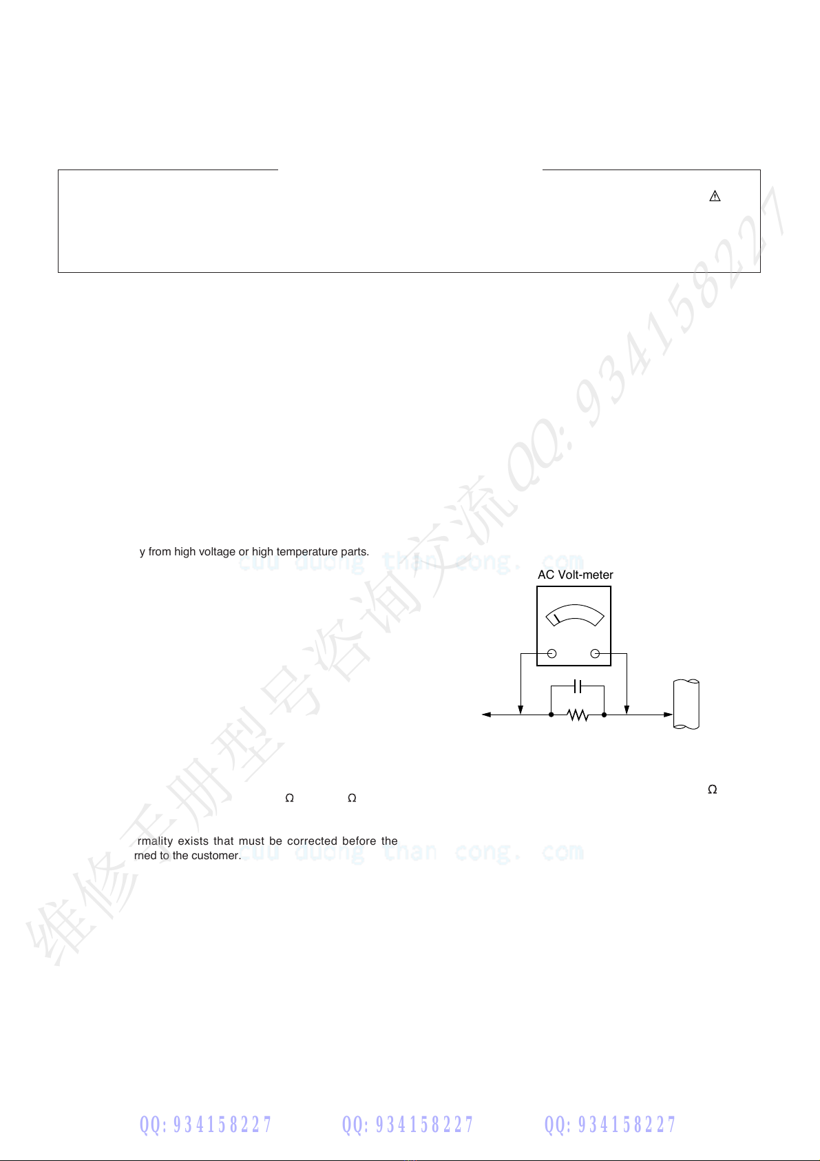
2.Testhighvoltageonlybymeasuring itwithan appropriatehigh
voltagemeterorother voltagemeasuringdevice(DVM,
FETVOM,etc)equipped withasuitablehigh voltageprobe.
Donot testhigh voltageby"drawing anarc".
3.Do notspray chemicalsonor nearthisreceiverorany ofits
assemblies.
4.Unlessspecified otherwisein thisservicemanual, clean
electricalcontacts onlyby applyingthefollowing mixture to the
contactswithapipecleaner, cotton-tippedstick or comparable
non-abrasiveapplicator;10 %(byvolume) Acetoneand90 %
(by volume) isopropyl alcohol (90 % -99% strength)
CAUTION: Thisisaflammablemixture.
Unlessspecifiedotherwiseinthisservicemanual,lubricationof
contactsinnot required.
5.Donotdefeatany plug/socket B+voltageinterlockswithwhich
receivers covered bythisservicemanual mightbeequipped.
6.Do not applyACpower to thisinstrumentand/orany of its
electricalassemblies unless all solid-state deviceheatsinksare
correctlyinstalled.
7.Alwaysconnectthetestreceiver ground leadto thereceiver
chassisgroundbefore connecting thetestreceiverpositive
lead.
Alwaysremovethetestreceiver ground lead last.
8. Ë-» ©·¬¸¬¸·- ®»½»·ª»®±²´§ ¬¸» ¬»-¬º·¨¬«®»- -°»½·º·»¼·²¬¸·-
-»®ª·½»³¿²«¿´ò
CAUTION: Donotconnectthetest fixture groundstraptoany
heatsinkinthisreceiver.
Electrostatically Sensitive(ES)Devices
Somesemiconductor (solid-state) devices can bedamagedeasily
by staticelectricity.Such componentscommonly are called
Û´»½¬®±-¬¿¬·½¿´´§Í»²-·¬·ª» øÛÍ÷Ü»ª·½»-ò Examplesof typicalES
devicesare integratedcircuitsandsome field-effecttransistors and
semiconductor"chip" components.Thefollowingtechniques
should beused to helpreducetheincidenceofcomponent
damagecaused bystaticbystaticelectricity.
1.Immediatelybefore handlingany semiconductor componentor
semiconductor-equipped assembly,drain offany electrostatic
charge onyourbodyby touching aknownearthground.
Alternatively,obtainandwearacommerciallyavailable
discharging wriststrap device, which should beremoved to
preventpotentialshockreasonsprior toapplying power to the
unitunder test.
2.After removingan electricalassemblyequipped withES
devices, placetheassemblyonaconductivesurfacesuchas
aluminumfoil, topreventelectrostaticcharge buildupor
exposureof theassembly.
3.Useonlyagrounded-tip solderingironto solder or unsolder ES
devices.
4.Useonlyananti-statictype solder removaldevice. Somesolder
removaldevicesnot classified as"anti-static"can generate
electrical charges sufficienttodamageESdevices.
5.Do not usefreon-propelledchemicals.Thesecangenerate
electrical charges sufficienttodamageESdevices.
6.DonotremoveareplacementESdevicefromitsprotective
packageuntilimmediatelybeforeyouarereadytoinstall it.
(MostreplacementESdevicesarepackagedwithleads
electricallyshortedtogether byconductivefoam,aluminumfoil
or comparableconductivematerial).
7.Immediatelybefore removingtheprotectivematerialfromthe
leadsofareplacementESdevice, touch theprotectivematerial
to thechassisorcircuitassembly into which thedevicewillbe
installed.
CAUTION: Be sure no power isapplied to thechassisorcircuit,
andobserveall other safetyprecautions.
8.Minimizebodilymotionswhenhandling unpackaged
replacementESdevices. (Otherwise harmless motionsuchas
thebrushing together ofyour clothes fabricor thelifting ofyour
foot fromacarpetedfloorcangenerate staticelectricity
sufficienttodamageanESdevice.)
GeneralSoldering Guidelines
1.Useagrounded-tip,low-wattagesoldering ironandappropriate
tipsizeandshapethatwill maintain tip temperature withinthe
rangeor 500 °Fto 600 °F.
2.Usean appropriate gaugeofRMAresin-core solder composed
of 60parts tin/40 partslead.
3.Keepthesoldering irontipclean and well tinned.
4.Thoroughlyclean thesurfaces tobesoldered.Useamallwire-
bristle(0.5inch,or 1.25 cm)brushwithametal handle.
Donot usefreon-propelledspray-oncleaners.
5.Usethefollowing unsoldering technique
a.Allow thesoldering irontip to reachnormal temperature.
(500 °Fto 600 °F)
b.Heatthecomponentlead until thesolder melts.
c.Quicklydrawthemeltedsolderwithan anti-static,suction-
typesolder removaldeviceorwithsolder braid.
CAUTION:Workquicklytoavoid overheatingthecircuit
board printed foil.
6.Usethefollowing solderingtechnique.
a.Allowthesolderingirontip toreachanormaltemperature
(500 °Fto 600 °F)
b.First, hold thesoldering irontip andsolder the strandagainst
thecomponentleaduntilthesoldermelts.
c.Quicklymovethesolderingirontipto thejunctionof the
componentleadandtheprintedcircuitfoil,andhold itthere
onlyuntilthesolderflowsontoandaround boththe
componentlead andthefoil.
CAUTION: Workquicklyto avoidoverheating thecircuit
board printed foil.
d.Closelyinspectthesolder areaandremoveanyexcessor
splashed solder withasmall wire-bristlebrush.
SERVICINGPRECAUTIONS
纸型号咨询交流QQ:934158227
QQ:934158227 QQ:934158227 QQ:934158227
维修手册型号咨询交流QQ:934158227
CuuDuongThanCong.com https://fb.com/tailieudientucntt

LGEInternalUseOnlyCopyright 2010 LGElectronics.Inc.Allrightsreserved.
Onlyfortrainingandservicepurposes
-5-
ICRemove/Replacement
Somechassiscircuitboardshaveslottedholes(oblong)through
which theIC leadsare inserted andthenbentflatagainstthe
circuitfoil.Whenholesare theslottedtype, thefollowingtechnique
should beusedto removeand replacetheIC.Whenworkingwith
boardsusing thefamiliarround hole, usethestandardtechnique
asoutlined inparagraphs5and6above.
λ³±ª¿´
1.DesolderandstraighteneachIC leadinoneoperationbygently
pryingupontheleadwiththesoldering irontip asthesolder
melts.
2.Drawawaythemelted solderwithan anti-staticsuction-type
solder removal device(or withsolderbraid)before removing the
IC.
λ°´¿½»³»²¬
1.Carefullyinsert thereplacementIC inthecircuitboard.
2.Carefullybend each IC leadagainstthecircuit foil pad and
solder it.
3.Clean thesoldered areaswithasmall wire-bristlebrush.
(Itisnot necessaryto reapplyacryliccoating totheareas).
"Small-Signal"DiscreteTransistor
Removal/Replacement
1.Removethedefectivetransistor byclippingitsleadsasclose as
possibletothecomponentbody.
2.Bend into a"U"shapetheendofeachofthreeleadsremaining
onthecircuitboard.
3.Bend into a"U"shapethereplacementtransistor leads.
4.Connectthereplacementtransistor leadsto thecorresponding
leadsextendingfromthecircuitboardandcrimpthe"U"with
long nosepliersto insuremetalto metalcontactthensolder
eachconnection.
PowerOutput, TransistorDevice
Removal/Replacement
1.Heatand removeall solder fromaround thetransistorleads.
2.Removetheheatsink mounting screw(if soequipped).
3.Carefullyremovethetransistor fromtheheatsinkofthecircuit
board.
4.Insert new transistor inthecircuitboard.
5.Solder each transistor lead,and clip off excesslead.
6.Replaceheatsink.
DiodeRemoval/Replacement
1.Removedefectivediodebyclippingitsleadsascloseas
possibleto diodebody.
2.Bend thetworemaining leadsperpendicularytothecircuit
board.
3.Observing diodepolarity,wrapeachleadofthenewdiode
around thecorresponding lead onthecircuitboard.
4.Securelycrimpeach connectionandsolder it.
5.Inspect(onthecircuitboardcopperside)thesolder joints of
thetwo "original"leads.If theyare not shiny,reheatthemandif
necessary,applyadditional solder.
Fuseand Conventional Resistor
Removal/Replacement
1.Clipeachfuse or resistor leadattopofthecircuitboardhollow
stake.
2.Securelycrimptheleadsofreplacementcomponentaround
notch atstaketop.
3.Solder theconnections.
CAUTION: Maintainoriginalspacingbetweenthereplaced
componentandadjacentcomponentsand thecircuitboardto
preventexcessivecomponenttemperatures.
Circuit BoardFoil Repair
Excessiveheatappliedto thecopper foil ofany printed circuit
boardwill weakentheadhesivethatbondsthefoil tothecircuit
boardcausing thefoil to separate fromor"lift-off"theboard.The
following guidelines andproceduresshouldbefollowedwhenever
thisconditionisencountered.
߬ ×Ýݱ²²»½¬·±²-
TorepairadefectivecopperpatternatIC connectionsusethe
following procedure to installajumper wire onthecopper pattern
side of thecircuit board. (Usethistechniqueonly onIC
connections).
1.Carefullyremovethedamaged copperpatternwith asharp
knife. (Removeonly asmuch copperasabsolutelynecessary).
2.carefullyscratchawaythesolderresist and acryliccoating(if
used)fromtheend of theremainingcopper pattern.
3.Bend asmall"U"in oneendofasmall gaugejumper wire and
carefullycrimpitaroundtheICpin.Solder theIC connection.
4.Routethejumperwire alongthepathoftheout-awaycopper
patternand let itoverlap thepreviouslyscrapedend ofthe good
copperpattern.Soldertheoverlappedareaandclip offany
excessjumper wire.
߬ Ѭ¸»® ݱ²²»½¬·±²-
Usethefollowing techniqueto repairthedefectivecopper pattern
atconnectionsother thanIC Pins.Thistechniqueinvolvesthe
installationofajumper wire onthecomponentsideofthecircuit
board.
1.Removethedefectivecopper patternwithasharpknife.
Removeatleast 1/4inchofcopper, toensure thatahazardous
conditionwill not existif thejumper wire opens.
2.Tracealongthecopperpatternfrombothsides ofthepattern
breakandlocatethenearestcomponentthatisdirectly
connected totheaffected copper pattern.
3.Connectinsulated 20-gaugejumperwire fromtheleadofthe
nearestcomponentononesideofthepatternbreak to thelead
of thenearestcomponentontheother side.
Carefullycrimpand solder theconnections.
CAUTION: Be suretheinsulatedjumper wire isdressedsothe
itdoesnot touch components or sharpedges.
纸型号咨询交流QQ:934158227
QQ:934158227 QQ:934158227 QQ:934158227
维修手册型号咨询交流QQ:934158227
CuuDuongThanCong.com https://fb.com/tailieudientucntt
Other manuals for 15EL9500
3
This manual suits for next models
1
Other LG OLED TV manuals

LG
LG OLED77GXPCA.AHK User manual

LG
LG 65EV960H User manual

LG
LG UltraGear 27GR95QE-B User manual

LG
LG 43UN570H0UA User manual

LG
LG OLED65G1PT / PVA Series User manual

LG
LG OLED77W9PUA User manual

LG
LG OLED55B6V-T Parts list manual

LG
LG OLEDSSE9PUA Parts list manual

LG
LG 15EL9500 User manual

LG
LG OLED55B6 Series Parts list manual

LG
LG 55EF9500-UA User manual

LG
LG OLED55B6 Series Parts list manual

LG
LG OLED55G2 Series User manual

LG
LG 55EG9A7V-ZB User manual

LG
LG OLED77G2PSA User manual

LG
LG EG9A7 Series Parts list manual

LG
LG OLED55E8PUA User manual

LG
LG OLED55CS A Series User manual

LG
LG OLED77M3 Series User manual

LG
LG EG91 User manual