A-9
MAKING CONNECTIONS
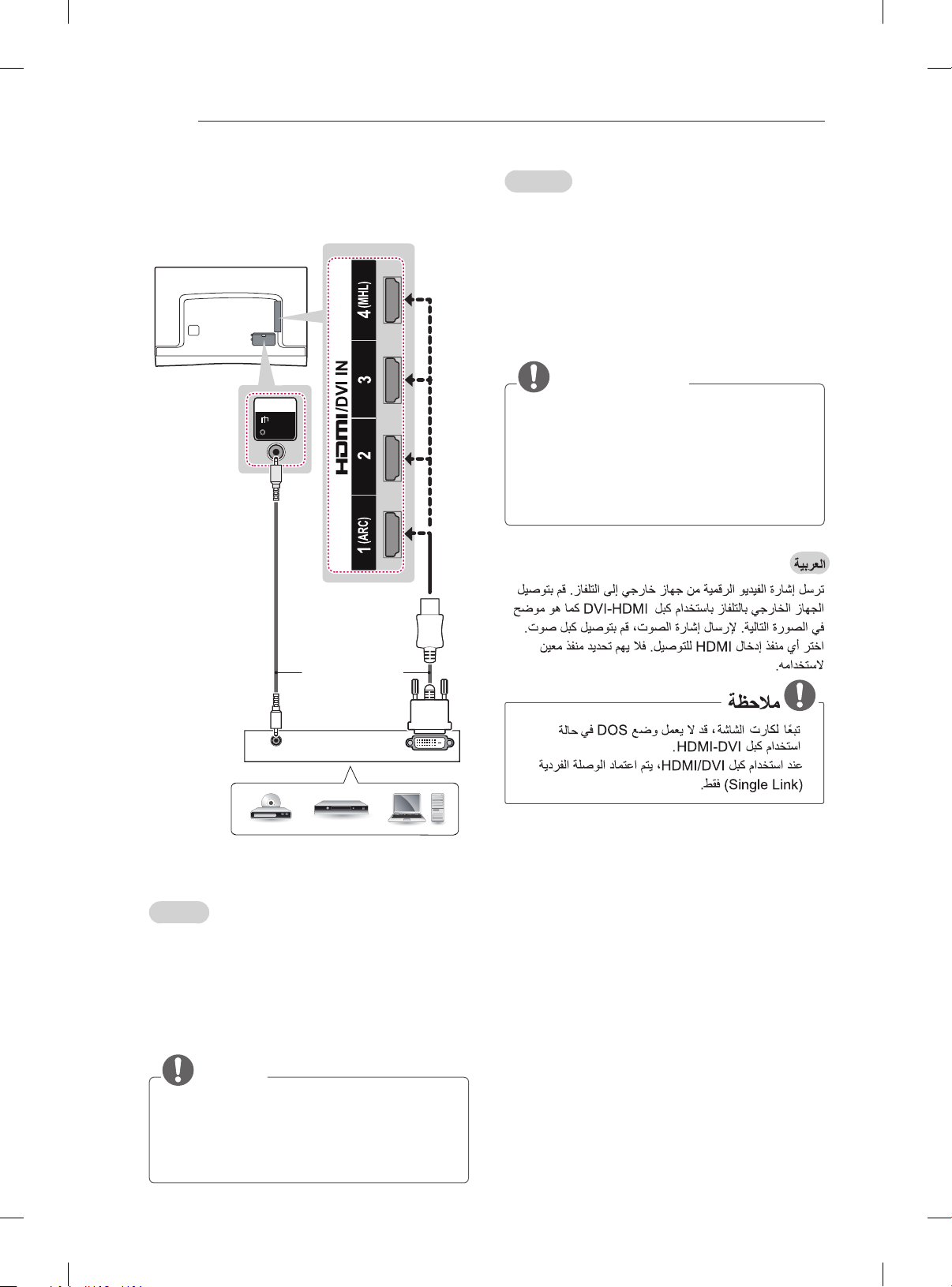
ARC (Audio Return Channel)
English
yAn external audio device that supports
SIMPLINK and ARC must be connected
using HDMI/DVI IN 1 (ARC) port.
yWhen connected with a high-speed HDMI
cable, the external audio device that
supports ARC outputs optical SPDIF without
additional optical audio cable and supports
the SIMPLINK function.
Français
yUn périphérique audio externe qui prend en
charge les technologies SIMPLINK et ARC
doit être connecté au port HDMI/DVI IN 1
(ARC).
ySi vous reliez un câble HDMI haut débit,
le périphérique audio externe qui prend en
charge les sorties ARC, prend également en
charge la sortie optique SPDIF sans câble
audio optique supplémentaire, ainsi que la
fonction SIMPLINK.
y
y
Français
Permet de transmettre les signaux vidéo et audio
numériques d’un périphérique externe vers la TV.
Connectez le périphérique externe et la TV avec
le câble HDMI comme indiqué sur l’illustration
suivante.
Choisissez un port d’entrée HDMI pour établir la
connexion. Peu importe le port que vous utilisez.
REMARQUE
yPour obtenir une meilleure qualité d’image,
il est recommandé d’utiliser la TV avec une
connexion HDMI.
yUtilisez le tout nouveau câble haut débit
HDMI™ avec la fonction CEC (contrôles
électroniques client).
yLes câbles HDMI™ haut débit sont testés
pour transporter un signal HD de 1080p ou
supérieur.
yFormats audio HDMI pris en charge : Dolby
Digital, DTS, PCM (jusqu'à 192 KHz, 32 KHz
/ 44,1 KHz / 48 KHz / 88 KHz / 96 KHz /
176 KHz / 192 KHz)
y
y
y
y