LG 42PG3500 User manual

Please read this manual carefully before operating
your TV.
Retain it for future reference.
Record model number and serial number of the TV.
Refer to the label on the back cover and quote this
information.
To your dealer when requiring service.
LCD TV
OWNER’S MANUAL
LCD TV MODELS
3322GG3355****
3377GG3355****
4422GG3355****
3322GG55******
3377GG5555****
4422GG5555****
4477GG5555****
5522GG5555****
3322GG7755****
3377GG7755****
4422GG7755****
4477GG7755****
5522GG7755****
PLASMA TV MODELS
4422PPGG2255****
5500PPGG2255****
4422PPGG3355****
5500PPGG3355****
5500PPGG4455****
4422PPGG6655****
5500PPGG6655****
5500PPGG7755****
Trade Mark of the DVB Digital Video
Broadcasting Project (1991 to 1996)
IIDD NNuummbbeerr((ss))::5095: 32 G5500 5093: 42PG6500
5096: 37 G5500 5094: 50PG6500
5097: 42 G5500 5526: 50PG4500
5442: 47 G5500 5527: 50PG7500
5443: 52 G5500 5567: 42PG3500
5602: 32 G7500 5566: 50PG3500
5601: 37 G7500 5669: 42PG2500
5603: 42 G7500 5670: 50PG2500
5604: 47 G7500
5605: 52 G7500
5716: 32 G3500
5717: 37 G3500
5718: 42 G3500
5720: 32 G5900
PLASMA TV
This feature is not available for all models.
(Except for 32/37/42/47/52 G75**)

“ This product incorporates copy protection technology that is protected by U.S. and
foreign patents, including patent numbers 5,315,448 and ,83 ,549, and other
intellectual property rights. The use of Macrovision’s copy protection technology in
the product must be authorized by Macrovision. Reverse engineering or disassembly
is prohibited. ”

1
ACCESSORIES
ACCESSORIES
Ensure that the following accessories are included with your TV. If an accessory is missing, please contact the
dealer where you purchased the TV.
Owner's
Manual
Owner's manual
Owner s Manual Batteries
OK
INPUTMODE
TV
D/A
DVD
EXIT
VOLPR
GUIDE
BACK
MENU
RATIO
I/II
VCR
POWER
123
456
789
0
Q.VIEW
LIST
INDEX
SLEEP
HOLD
REVEAL
?
SUBTITLE
TEXT
INPUT
BRIGHT
MUTE
TV/RADIO
UPDATE
SIMPLINK
INFO i
FAV
TIME
Remote Control
Power Cord
Polishing Cloth
Polishing cloth for use on the
screen.
ightly wipe any stains or fingerprints on
the surface of the TV with the polishing
cloth.
Do not use excessive force. This may
cause scratching or discolouration.
Protection Cover
PPAASSMMAA TTVV mmooddeellss
CCDD TTVV mmooddeellss
Cable management clip
(50PG65**,
50PG75** only)
(42/50PG25**,
42/50PG35**,
50PG45** only)
(32/37/42LG35**, 32/37/42LG55**,
32LG59**, 32LG75** only)
Cable Holder
(42PG25**/ 42PG35**/
42PG65**: 1EA, 50PG25**/
50PG35**/ 50PG45**: 2EA)
Ferrite Core
(This feature is not available
for all models.)
Bolts for stand assembly
(Refer to p.8)
x 4 x 4
1-screw for stand fixing
(Refer to p.5)
oror
Ferrite core can be used to reduce the electromagnetic
wave when connecting the power cord.
The closer the location of the ferrite core to the power
plug, the better it is.
Use of ferrite core (This feature is not available for all models.)
Install the power plug closely.

2
CONTENTS
CONTENTS
ACCESSORIES
. . . . . . . . . . . . . . . . . . . . . . . . . . . . . . . . . . . . . . . . . . . . .
1
PREPARATION
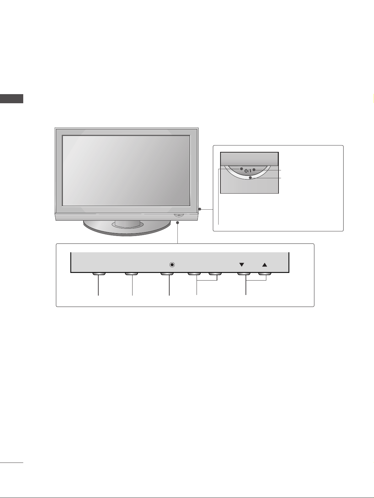
Front Panel Controls . . . . . . . . . . . . . . . . . . . . . . . . 4
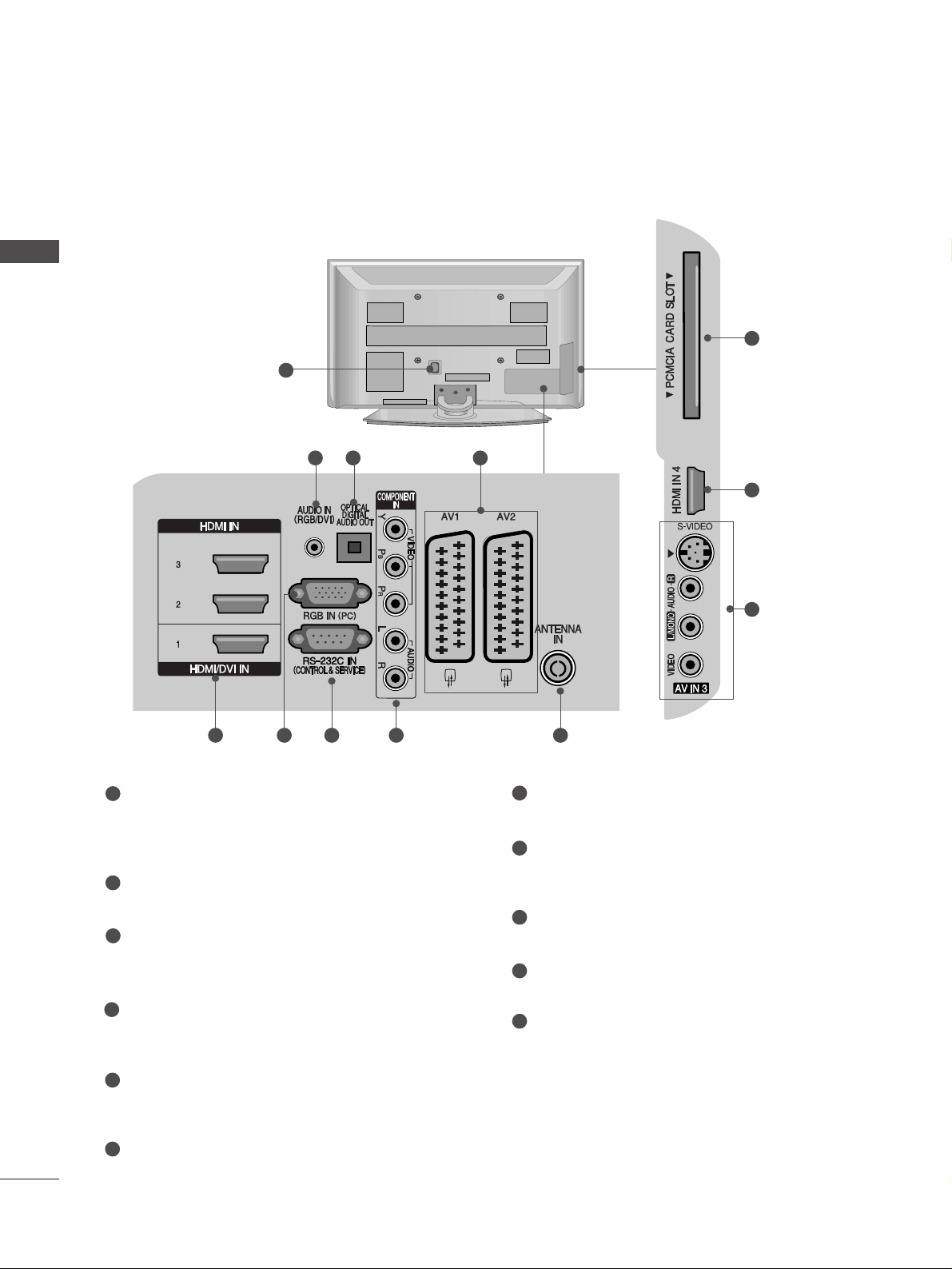
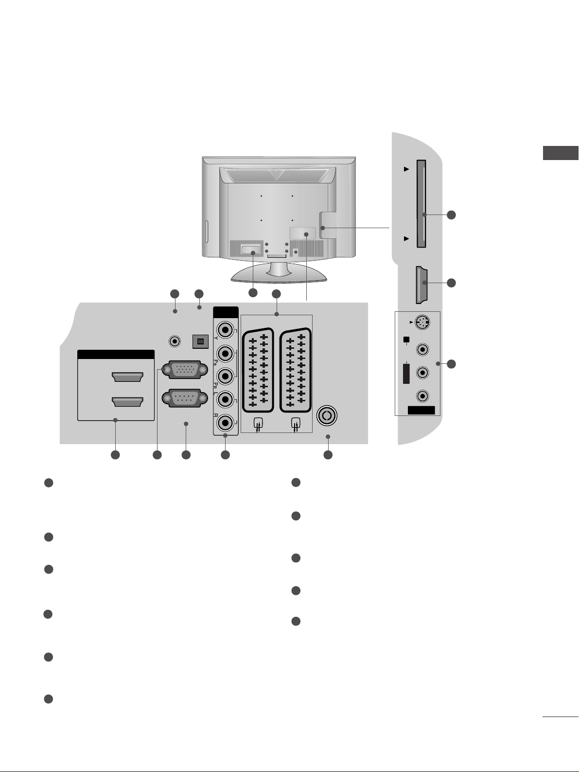
Back Panel Information . . . . . . . . . . . . . . . . . . . . . . 6
Stand Installation . . . . . . . . . . . . . . . . . . . . . . . . . . . 8
Please set it up carefully so the product
does not fall over . . . . . . . . . . . . . . . . . . . . . . . . . . . 9
Back Cover for Wire Arrangement . . . . . . . . . . . . . 10
Desktop Pedestal Installation . . . . . . . . . . . . . . . . . 12
Wall Mount: Horizontal installation . . . . . . . . . . . . 12
Antenna Connection . . . . . . . . . . . . . . . . . . . . . . . . 13
EXTERNAL EQUIPMENT SETUP
HD Receiver Setup . . . . . . . . . . . . . . . . . . . . . . . . 14
DVD Setup . . . . . . . . . . . . . . . . . . . . . . . . . . . . . . . . 16
VCR Setup . . . . . . . . . . . . . . . . . . . . . . . . . . . . . . . . 19
Digital Audio Out Setup . . . . . . . . . . . . . . . . . . . . . 22
Insertion of CI module . . . . . . . . . . . . . . . . . . . . . . 22
Other A/V Source Setup . . . . . . . . . . . . . . . . . . . . 23
PC Setup . . . . . . . . . . . . . . . . . . . . . . . . . . . . . . . . . 24
- Screen Setup for PC Mode . . . . . . . . . . . . . . . 27
WATCHING TV / PROGRAMME CONTROL
Remote Control Key Functions . . . . . . . . . . . . . . . . 31
Turning on the TV . . . . . . . . . . . . . . . . . . . . . . . . . . 33
Programme Selection . . . . . . . . . . . . . . . . . . . . . . . 34
Volume Adjustment . . . . . . . . . . . . . . . . . . . . . . . . 34
On-Screen Menus Selection and Adjustment . . . . 35
Auto Programme Tuning (In Digital Mode) . . . . . . 36
Manual Programme Tuning (In Digital Mode) . . . . 37
Programme Edit (In Digital Mode) . . . . . . . . . . . . . 38
Booster (In Digital Mode only) . . . . . . . . . . . . . . . 40
Software Update (In Digital Mode only) . . . . . . . . 41
Diagnostics (In Digital Mode only) . . . . . . . . . . . . 42
CI Information (In Digital Mode only) . . . . . . . . . . 43
Auto Programme Tuning (In Analogue Mode) . . . . . 44
Manual Programme Tuning (In Analogue Mode)
. . . . . . . 45
Fine Tuning (In Analogue Mode) . . . . . . . . . . . . . . 46
Assigning a Station Name (In Analogue Mode)
. . . . . . 46
Programme Edit (In Analogue Mode)
. . . . . . . . . . . . . 47
Selecting the Programme Table . . . . . . . . . . . . . . 49
Input Source Selection . . . . . . . . . . . . . . . . . . . . . 50
SIMP INK Function . . . . . . . . . . . . . . . . . . . . . . . . . 51
EPG (ELECTRONIC PROGRAMME GUIDE)
(IN DIGITAL MODE)
Switch on/off EPG . . . . . . . . . . . . . . . . . . . . . . . . . . 53
Select programme . . . . . . . . . . . . . . . . . . . . . . . . . . 53
Button function in NOW/NEXT guide mode . . . . . 54
Button Function in 8 Day Guide Mode . . . . . . . . . . 54
Button function in date change mode . . . . . . . . . . . 54
Button function in extended description box . . . . . 55
Button function in record/remind setting mode . . . 55
Button function in timer list mode . . . . . . . . . . . . . . 55
PICTURE CONTROL
Picture Size (Aspect Ratio) Control . . . . . . . . . . . . . . . . . 56
Preset Picture Settings
- Picture Mode-Preset . . . . . . . . . . . . . . . . . . . . . . . . . . 58
-
Auto Colour Tone Control (Warm/Medium/Cool)
. . .59
Manual Picture Adjustment
- Picture Mode-User option . . . . . . . . . . . . . . . . . . . . . 60
- Colour Tone - User option . . . . . . . . . . . . . . . . . . . . .61
XD - Picture Improvement Technology . . . . . . . . . . . . . . 62
XD Demo . . . . . . . . . . . . . . . . . . . . . . . . . . . . . . . . . . . . . . 63
Advanced - Cinema/Real Cinema . . . . . . . . . . . . . . . . . . . 64
Advanced - Black(Darkness) evel . . . . . . . . . . . . . . . . . . 64
Advanced - Trumotion . . . . . . . . . . . . . . . . . . . . . . 65
Picture Reset . . . . . . . . . . . . . . . . . . . . . . . . . . . . . . . . . . . . 66
TruMotion Demo . . . . . . . . . . . . . . . . . . . . . . . . . . 66
Image Sticking Minimization(ISM) Method . . . . . . . . . . . 67
ow-Power Picture Mode . . . . . . . . . . . . . . . . . . . . . . . . . . 68

3
CONTENTS
SOUND & LANGUAGE CONTROL
Auto Volume eveler . . . . . . . . . . . . . . . . . . . . . . . . 69
Preset Sound Settings - Sound Mode . . . . . . . . . . 70
Sound Setting Adjustment - User Mode . . . . . . . . . . 71
Balance . . . . . . . . . . . . . . . . . . . . . . . . . . . . . . . . . . . 72
TV Speakers On/Off Setup . . . . . . . . . . . . . . . . . . 73
Selecting Digital Audio . . . . . . . . . . . . . . . . . . . . . . 74
I/II
-
Stereo/Dual Reception (In Analogue Mode Only)
. . . . 75
-
NICAM Reception (In Analogue Mode Only) . . . . . . .
76
- Speaker Sound Output Selection . . . . . . . . . . 76
On-Screen Menu anguage
/Country Selection
. . . . 77
anguage selection (In Digital Mode only) . . . . . . 78
TIME SETTING
Clock Setup . . . . . . . . . . . . . . . . . . . . . . . . . . . . . 79
Auto On/Off Timer Setting . . . . . . . . . . . . . . . . . 80
Auto Shut-off Setting . . . . . . . . . . . . . . . . . . . . . . 81
Sleep Timer Setting . . . . . . . . . . . . . . . . . . . . . . . 82
PARENTAL CONTROL / RATINGS
Set Password & ock System . . . . . . . . . . . . . . . . . 83
Parental Control . . . . . . . . . . . . . . . . . . . . . . . . . . . 84
TELETEXT
Switch on/off . . . . . . . . . . . . . . . . . . . . . . . . . . . . . . 85
SIMP E Text . . . . . . . . . . . . . . . . . . . . . . . . . . . . . . . 85
TOP Text . . . . . . . . . . . . . . . . . . . . . . . . . . . . . . . . . 85
FASTEXT . . . . . . . . . . . . . . . . . . . . . . . . . . . . . . . . . 86
Special Teletext Functions . . . . . . . . . . . . . . . . . . . . 86
APPENDIX
Troubleshooting . . . . . . . . . . . . . . . . . . . . . . . . . . 87
Maintenance . . . . . . . . . . . . . . . . . . . . . . . . . . . . 89
Product Specifications . . . . . . . . . . . . . . . . . . . . . 90
Programming the Remote Control . . . . . . . . . . . . 93
IR Codes . . . . . . . . . . . . . . . . . . . . . . . . . . . . . . . . 95
External Control Device Setup . . . . . . . . . . . . . . 97

PR
VOL
-+
OK
MENU
INPUT
4
PREPARATION
FRONT PANEL CONTROLS
PREPARATION
AImage shown may differ from your TV.
AIf your TV has a protection film attached, remove the film and then wipe the TV with a polishing cloth.
PLASMA TV Models
PROGRAMMEVOLUMEMENU OKINPUT
PR
VOL
-+
OK
MENU
INPUT
Remote Control Sensor
POWER
Power/Standby Indicator
• illuminates red in standby mode.
• illuminates green when the TV is
switched on.
PR
PR
VOL
VOL
- +
OK
OK
MENU
MENU
INPUT
INPUT

5
PREPARATION
Intelligent Sensor
Adjusts picture according to the surrounding
conditions. (32/37/42/47/52 G5***,
32/37/42/47/52 G75** only)
POWER
Remote Control Sensor
Power/Standby Indicator
• illuminates red in standby mode.
• illuminates blue when the TV is switched on.
Note: You can adjust PPoowweerr IInnddiiccaattoorrin
the OPTION menu.
PR
VOL
MENU
INPUT
OK
+
-
OK
MENU
INPUT
PR
VOL
PROGRAMME
VOLUME
OK
MENU
INPUT
Attaching the TV to a desk (Only 32/37/42LG35**, 32/37/42LG55**, 32LG59**, 32LG75**)
WARNING
!
GG To prevent TV from falling over, the TV should be securely attached to the floor/wall per installation
instructions. Tipping, shaking, or rocking the machine may cause injury.
The TV must be attached to desk so it cannot be pulled in a forward/backward direction, potentially causing
injury or damaging the product. Use only an attached screw.
1-Screw
(provided as parts of the product)
Desk
Stand
LCD TV Models
or

6
PREPARATION
PREPARATION
PLASMA
TV Models
BACK PANEL INFORMATION
A
Image shown may differ from your TV.
Power Cord Socket
This TV operates on an AC power. The voltage is
indicated on the Specifications page. Never
attempt to operate the TV on DC power.
AUDIO IN (RGB/DVI)
Connect the audio from a PC.
OPTICAL DIGITAL AUDIO OUT
Connect digital audio from various types of equipment.
Note: In standby mode, these ports do not work.
Euro Scart Socket (AV1/AV2)
Connect scart socket input or output from an
external device to these jacks.
HDMI IN 1/2/3/4
Connect a HDMI signal to HDMI IN. Or DVI (VIDEO)
signal to HDMI/DVI port with DVI to HDMI cable.
RGB IN (PC)
Connect the output from a PC.
RS-232C IN (CONTROL & SERVICE) PORT
Connect to the RS-232C port on a PC.
Component Input
Connect a component video/audio device to
these jacks.
Antenna Input
Connect RF antenna to this jack.
PCMCIA (Personal Computer Memory Card
International Association) Card Slot
AV (Audio/Video) IN 3
Connect audio/video output from an external
device to these jacks.
S-VIDEO
Connect S-Video out from an S-VIDEO device.
1
2
3
4
5
7
8
9
10
11
1
10
5
11
24
3
95 7 8

RGB IN
(PC)
OPTICAL
DIGITAL
AUDIO OUT
AV 1 AV 2
ANTENNA IN
RS-232C IN
(CONTROL & SERVICE)
AUDIO IN
(RGB/DVI)
HDMI/DVI IN
2
1(DVI)
COMPONENT
IN
VIDEO AUDIO
AV IN 3
L/ MONO
R
AUDIO
HDMI IN 3 PCMCIA CARD SLOT
VIDEO
S-VIDEO
7
PREPARATION
LCD TV Models
Power Cord Socket
This TV operates on an AC power. The voltage is
indicated on the Specifications page. Never
attempt to operate the TV on DC power.
AUDIO IN (RGB/DVI)
Connect the audio from a PC.
OPTICAL DIGITAL AUDIO OUT
Connect digital audio from various types of equipment.
Note: In standby mode, these ports do not work.
Euro Scart Socket (AV1/AV2)
Connect scart socket input or output from an
external device to these jacks.
HDMI IN 1/2/3
Connect a HDMI signal to HDMI IN. Or DVI (VIDEO)
signal to HDMI/DVI port with DVI to HDMI cable.
RGB IN (PC)
Connect the output from a PC.
RS-232C IN (CONTROL & SERVICE) PORT
Connect to the RS-232C port on a PC.
Component Input
Connect a component video/audio device to
these jacks.
Antenna Input
Connect RF antenna to this jack.
PCMCIA (Personal Computer Memory Card
International Association) Card Slot
AV (Audio/Video) IN 3
Connect audio/video output from an external
device to these jacks.
S-VIDEO
Connect S-Video out from an S-VIDEO device.
1
2
3
4
5
7
8
9
10
11
2 43
AV IN 3
L/MONO
R
AUDIO
AUDIO
HDMI IN 3
HDMI IN 3
PCMCIA CARD SLOT
PCMCIA CARD SLOT
VIDEO
VIDEO
S-VIDEO
95 7 8
10
5
11
1

8
PREPARATION
PREPARATION
STAND INSTALLATION
(Only 32/37/42LG35**, 32/37/42LG5***, 32/37/42LG75**)
13
4
Carefully place the TV screen side down on a
cushioned surface to protect the screen from
damage.
2Assemble the parts of the ssttaanndd bbooddyywith
ccoovveerr bbaasseeof the TV.
Assemble the TV as shown.
Fix the 4 bolts securely using the holes in the
back of the TV.
Swivel Stand
After installing the TV, you can adjust the TV set
manually to the left or right direction by 20 degrees
to suit your viewing position.
Stand Body
Cover Base
A
When assembling the desk type stand, check whether the bolt is fully tightened. (If not tightened fully, the
product can tilt forward after the product installation.) If you tighten the bolt with excessive force, the bolt
can deviate from abrasion of the tightening part of the bolt.

9
PLEASE SET IT UP CAREFULLY SO THE PRODUCT DOES NOT
FALL OVER.
■You should purchase necessary components to fix the TV to the wall on the market.
■Position the TV close to the wall to avoid the possibility of it falling when pushed.
■The instructions shown below are a safer way to set up the TV, which is to fix it to the wall, avoiding the possi-
bility of it falling forwards if pulled. This will prevent the TV from falling forward and causing injury. This will
also prevent the TV from damage. Ensure that children do not climb or hang from the TV.
NOTE
!
G When moving the TV undo the cords first.
G Use a platform or cabinet strong and large enough to support the size and weight of the TV.
G To use the TV safely make sure that the height of the bracket on the wall and on the TV is the same.
3
1
2
Use the eye-bolts or TV brackets/bolts to fix the TV to the wall as shown in the picture.
(If your TV has bolts in the eyebolts, loosen these bolts.)
* Insert the eye-bolts or TV brackets/bolts and tighten them securely in the upper holes.
Secure the wall brackets with the bolts on the wall. Match the height of the bracket that is mounted
on the wall.
3Use a sturdy rope to tie the TV. It is safer to tie the rope so it becomes horizontal between the wall
and the TV.
PREPARATION
2
1
2
1

10
PREPARATION
PREPARATION
BACK COVER FOR WIRE ARRANGEMENT
Connect the cables as necessary.
To connect additional equipment, see the
EExxtteerrnnaall eeqquuiippmmeenntt SSeettuuppsection.
1
Install the CCAABBEE MMAANNAAGGEEMMEENNTT CCIIPPas shown.
2
■
Image shown may differ from your TV.
CABLE MANAGEMENT CLIP
Plasma TV models
Connect the cables as necessary.
To connect additional equipment, see the
EExxtteerrnnaall eeqquuiippmmeenntt SSeettuuppsection.
1
Install the CCAABBEE MMAANNAAGGEEMMEENNTT CCIIPPas shown.
2
CABLE MANAGEMENT CLIP
42/50PG25**, 42/50PG35**,
42PG65**, 50PG45** 50PG65**, 50PG75**
Fix the CCaabbllee HHoollddeerras
shown and bundle the
cables.
42/50PG25**, 42/50PG35**,
50PG45**

11
LCD TV models
Connect the cables as necessary.
To connect additional equipment, see the
External Equipment Setup section of the
manual.
1
Open the CCAABBEE MMAANNAAGGEEMMEENNTT CCIIPPas
shown and manage the cables.
2
CABLE MANAGEMENT CLIP
Fit the CCAABBEE MMAANNAAGGEEMMEENNTT CCIIPPas
shown.
3
PREPARATION
Hold the CCAABBEE MMAANNAAGGEEMMEENNTT CCIIPPwith both hands and pull it upward.
For the 42PG65** model, press the center of the CCAABBEE MMAANNAAGGEEMMEENNTT CCIIPP and then lift up it.
NOTE
!
GGDo not use the CABLE MANAGEMENT CLIP to lift the TV.
- If the TV is dropped, you may be injured or the TV may be damaged.
HHooww ttoo rreemmoovvee tthhee ccaabbllee mmaannaaggeemmeenntt cclliipp
50PG65**/50PG75**
42PG65**
42/50PG25**,
42/50PG35**, 50PG45**
Separate CAB E
MANAGEMENT from
TV by pressing two
latches.

12
PREPARATION
PREPARATION
DESKTOP PEDESTAL INSTALLATION
R
For adequate ventilation allow a clearance of 4” (10cm) all around the TV.
EARTHING
Ensure that you connect the earth wire to prevent possible
electric shock. Do not try to earth the TV by connecting it
to telephone wires, lightening rods or gas pipes.
Power Supply
Circuit
breaker
■The TV can be installed in various ways such as on a wall or on a desktop etc.
■The TV is designed to be mounted horizontally.
4 inches
4 inches 4 inches 4 inches
WALL MOUNT: HORIZONTAL INSTALLATION
For adequate ventilation allow a clearance of 4” (10cm) all around the TV. We recommend that you use a
wall mounting bracket of G brand when mounting the TV to a wall.
4 inches
4 inches
4 inches 4 inches
4 inches
When installing the wall-mounted
unit, use the protection cover for
desk-type stand installation. Insert
the PPRROOTTEECCTTIIOONN CCOOVVEERRinto
the TV until clicking sound.
Not using the desk-type stand
AImage shown may differ from your TV.
< PLASMA TV > < LCD TV >
or

13
ANTENNA IN
ANTENNA IN
■For optimum picture quality, adjust antenna direction.
■An antenna cable and converter are not supplied.
■To prevent damage do not connect to the mains outlet until all connections are made between the devices.
Multi-family Dwellings/Apartments
(Connect to wall antenna socket)
Single-family Dwellings /Houses
(Connect to wall jack for outdoor antenna)
Outdoor
Antenna
(VHF, UHF)
Wall
Antenna
Socket
RF Coaxial Wire (75 ohm)
ANTENNA CONNECTION
Antenna
UHF
Signal
Amplifier
VHF
■In poor signal areas, to achieve better picture quality it may be necessary to install a signal amplifier to the
antenna as shown above.
■If signal needs to be split for two TVs,use an antenna signal splitter for connection.
AV 1 AV 2
ANTENNA
IN
VARIABLE
AUDIO OUT
VIDEO
AUDIO
COMPONENT IN
AV IN 3
L/MONO
R
AUDIO
VIDEO
HDMI IN
12
RGB IN
S-VIDEO
PREPARATION

14
EXTERNAL EQUIPMENT SETUP
HD RECEIVER SETUP
■This TV can receive Digital RF/Cable signals without an external digital set-top box. However, if you do receive
Digital signals from a digital set-top box or other digital external device, refer to the diagram as shown below.
RGB IN
(PC)
OPTICAL
DIGITAL
AUDIO OUT
AV
RS-232C IN
(CONTROL & SERVICE)
AUDIO IN
(RGB/DVI)
HDMI/DVI IN
2
1(DVI)
COMPONENT
IN
VIDEO AUDIO
Connecting with a component cable
Connect the video outputs (Y, PB, PR)of the digital set
top box to the CCOOMMPPOONNEENNTT IINN VVIIDDEEOOjacks on
the TV.
Connect the audio output of the digital set-top box to
the CCOOMMPPOONNEENNTT IINN AAUUDDIIOOjacks on the TV.
Turn on the digital set-top box.
(Refer to the owner’s manual for the digital set-top
box.)
Select COMPONENT input source using the
IINNPPUUTT button on the remote control.
2
3
4
1
Signal
480i/576i
480p/576p
720p/1080i
108 0 p
Component
Yes
Yes
Yes
Yes
(Only 32 G59**,
37/42/47/52 G55**,
32/37/42/47/52 G75**,
50PG45**, 50PG75**)
HDMI1/2/3/4
(HDMI4 : only P ASMA TV Models)
No
Yes
Yes
Yes
1 2
■To avoid damaging any equipment, never plug in any power cords until you have finished connecting all equipment.
■This section on EXTERNAL EQUIPMENT SETUP mainly uses diagrams for the LCD TV models.

15
RGB IN
(PC)
RS-232C IN
(CONTROL & SERVICE)
HDMI/DVI IN
2
1(DVI)
VIDEO AUDIO
HDMI-DTV OUTPUT
Connecting a set-top box with an HDMI cable
Connect the digital set-top box to HHDDMMII IINN 22jack on
the TV.
Turn on the digital set-top box.
(Refer to the owner’s manual for the digital set-top box.)
Select HDMI2 input source using the IINNPPUUTTbutton
on the remote control.
If connected to HHDDMMII IINN 33(or HHDDMMII IINN 44) jack,
select HDMI3 (or HDMI4) input source.
2
3
1
1
RGB IN
(PC)
OPTICAL
DIGITAL
AUDIO OUT
AV 1
RS-232C IN
(CONTROL & SERVICE)
AUDIO IN
(RGB/DVI)
HDMI/DVI IN
2
1(DVI)
COMPONENT
IN
VIDEO AUDIO
12
Connect the digital set-top box to HHDDMMII//DDVVII IINN
11((DDVVII)) jack on the TV.
Connect the audio output of the digital set-top box to
the AAUUDDIIOO IINN ((RRGGBB//DDVVII)) jack on the TV.
Turn on the digital set-top box. (Refer to the owner’s
manual for the digital set-top box.)
Select HDMI1 input source using the IINNPPUUTTbutton
on the remote control.
2
3
4
1
Connecting with a HDMI to DVI cable
EXTERNAL EQUIPMENT SETUP

16
EXTERNAL EQUIPMENT SETUP
DVD SETUP
Connecting with a component cable
Component Input ports
To achieve better picture quality, connect a DVD player to the component input ports as shown below.
Component ports on the TV
YPBPR
Video output ports
on DVD player
Y
Y
Y
Y
PB
B-Y
Cb
Pb
PR
R-Y
Cr
Pr
Connect the video outputs (Y, PB, PR)of the DVD to the
CCOOMMPPOONNEENNTT IINN VVIIDDEEOOjacks on the TV.
Connect the audio outputs of the DVD to the
CCOOMMPPOONNEENNTT IINN AAUUDDIIOOjacks on the TV.
Turn on the DVD player, insert a DVD.
Select COMPONENT input source using the IINNPPUUTT
button on the remote control.
Refer to the DVD player's manual for operating
instructions.
2
3
4
5
1
RGB IN
(PC)
OPTICAL
DIGITAL
AUDIO OUT
AV
RS-232C IN
(CONTROL & SERVICE)
AUDIO IN
(RGB/DVI)
HDMI/DVI IN
2
1(DVI)
COMPONENT
IN
VIDEO AUDIO
AV IN 3
L/ MONO
R
AUDIO
HDMI IN 3 PCMCIA CARD SLOT
VIDEO
S-VIDEO
1 2

17
Connecting with a Euro scart
Connect the Euro scart socket of the DVD to the AAVV11
Euro scart socket on the TV.
Turn on the DVD player, insert a DVD.
Select AV 1 input source using the IINNPPUUTTbutton on
the remote control.
If connected to AV 2 Euro scart socket, select AV 2
input source.
Refer to the DVD player's manual for operating
instructions.
2
3
4
1
(PC)
OPTICAL
DIGITAL
AUDIO OUT
AV 1 AV 2
ANTENNA IN
C IN
SERVICE)
COMPONENT
IN
VIDEO AUDIO
AV IN 3
L/ MONO
R
AUDIO
HDMI IN 3 PCMCIA CARD SLOT
VIDEO
S-VIDEO
(R) AUDIO (L)
AUDIO/
VIDEO
1
NOTE
!
GGIf you want to use the EURO scart cable, you have to use
the signal shielded Euro scart cable.
Connecting with a S-Video cable
AV IN 3
L/L/MONOMONO
R
AUDIOAUDIO
HDMI IN 3HDMI IN 3 PCMCIA CARD SLOTPCMCIA CARD SLOT
VIDEOVIDEO
S-VIDEO
L R
S-VIDEOVIDEO
OUTPUT
SWITCH
ANT IN
ANT OUT
Connect the S-VIDEO output of the DVD to the SS--
VVIIDDEEOOinput on the TV.
Connect the audio outputs of the DVD to the AAUUDDIIOO
input jacks on the TV.
Turn on the DVD player, insert a DVD.
Select AV 3 input source using the INPUT button on
the remote control.
Refer to the DVD player's manual for operating
instructions.
2
3
4
5
1
12
EXTERNAL EQUIPMENT SETUP

18
EXTERNAL EQUIPMENT SETUP
RGB IN
(PC)
DIGITAL
AUDIO OUT
AV
RS-232C IN
(CONTROL & SERVICE)
AUDIO IN
(RGB/DVI)
HDMI/DVI IN
2
1(DVI)
IN
VIDEO AUDIO
AV IN 3
L/ MONO
R
AUDIO
HDMI IN 3 PCMCIA CARD SLOT
VIDEO
S-VIDEO
Connecting HDMI cable
Connect the HDMI output of the DVD to the HHDDMMII
IINN 22jack on the set.
Select HDMI2 input source using the IINNPPUUTTbutton
on the remote control.
If connected to HHDDMMII IINN 33(or HHDDMMII IINN 44) jack,
select HDMI3 (or HDMI4) input source.
Refer to the DVD player's manual for operating
instructions.
1
2
3
GGThe TV can receive video and audio signals simultaneously
when using a HDMI cable.
GGIf the DVD does not support Auto HDMI, you must set the
output resolution appropriately.
NOTE
!
1
This manual suits for next models
23
Table of contents
Other LG Plasma TV manuals

LG
LG 42 2P PQ Q1 11 User manual

LG
LG 42PQ210R User manual

LG
LG 50PN650T.ADK User manual

LG
LG RU-42PZ90 - Stand For 42 Inch Plasma EDTV... User manual

LG
LG 60PB6600 User manual

LG
LG 42PQ20 Series User manual

LG
LG 50PK950N User manual

LG
LG 50PM9700 User manual

LG
LG 50PY2DR User manual

LG
LG 50PB560B User manual
Popular Plasma TV manuals by other brands

Panasonic
Panasonic Viera TH-P55ST30A operating instructions

Philips
Philips 42 IN PLASMA FLAT TV HDTV MONITOR 42FD9954 Specifications

Samsung
Samsung PS51E6505 user manual

Optoma
Optoma SP50A Specification sheet

Panasonic
Panasonic Viera TC-P50U50 owner's manual

Panasonic
Panasonic TC-P42C1 - 41.6" Plasma TV operating instructions