- 8 - LGE Internal Use OnlyCopyright©2007 LG Electronics. Inc. All right reserved.
Only or training and service purposes
( ) Component1, RGB adjustment method.
1) Select Component1, RGB as the input with Color Bar
Pattern in 1080p 60Hz mode and select ‘Component1’
as input mode.
2) A ter receiving signal or at least 1 second, press the
ADJ Key on the Service R/C to enter the ‘Ez - Adjust’
and select the ‘2. ADC 480i Comp1/RGB’. Pressing the
Vol+ Key to adjust the component1.
3) When the adjustment is normally completed, the
message ‘ADC Component1 Success’ is displayed, or i
not, the message ‘ADC Component1 1080P Fail’ is
displayed. A ter adjusting the Component1 is
completed, it is automatically switched to the RGB-DTV
mode, and the RGB adjustment starts. I adjusting is
normally completed, the message ‘ADC RGB 1080P
Success’ is displayed.
4) When the adjustment is not normally completed, check
the pattern or the adjustment condition, and then adjust
it again. The error message is same to (4)) o (1)
5) A ter adjustment is complete, exit the adjustment mode
by pressing the ADJ KEY.
(MSPG-925FA : -> model : 225, pattern : 65)
5. Video Set Adjustment
It is the adjustment to reduce the color di erence o the RF
and the video signal, which adjusts Analog RF, AV-PAL, and
AV-NTSC.
5-1. Adjustment method
(1) Analog RF and AV-PAL adjustment method.
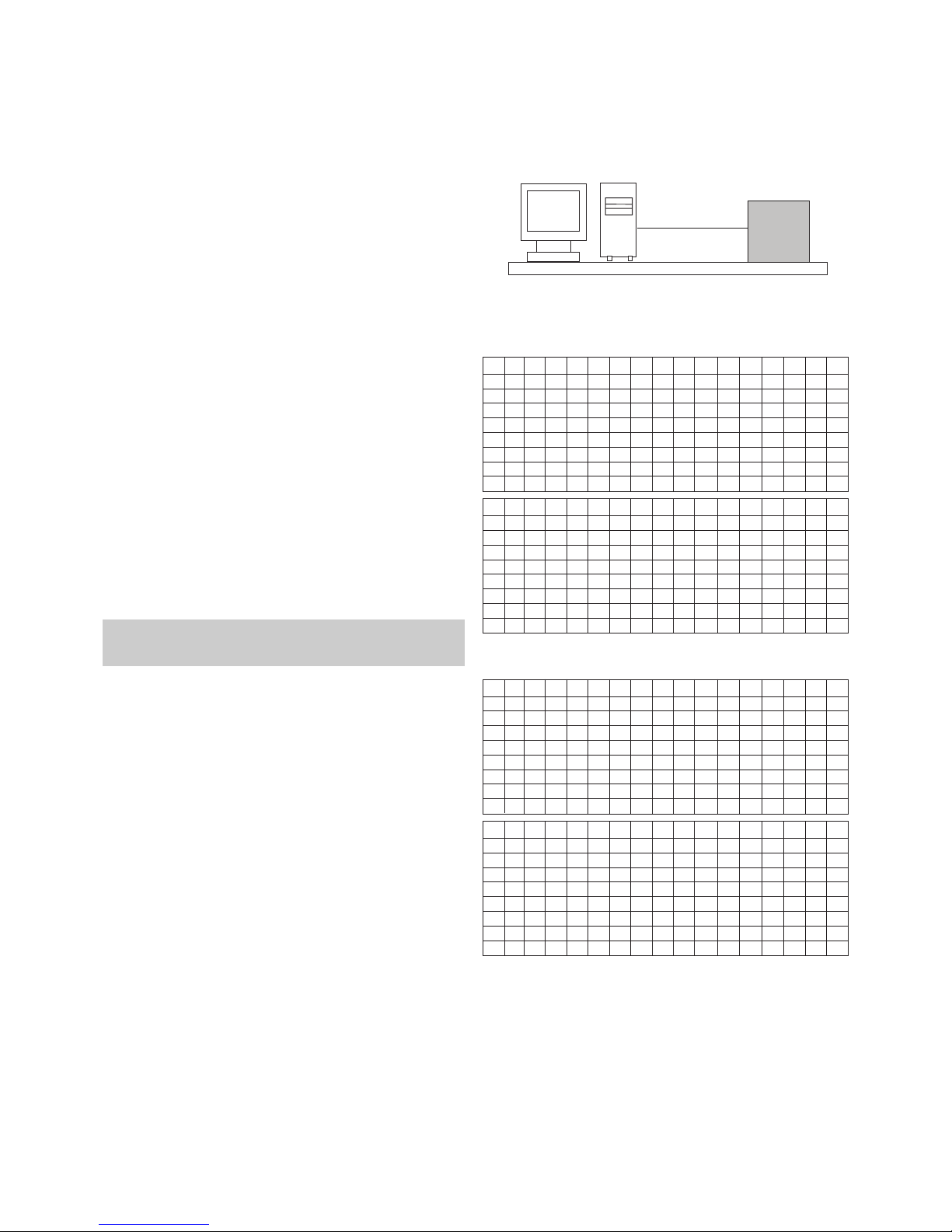
1) Connect the Video Signal Generator (Master) to the AV
input o the TV via the AV output. At this time, when
entering the input pattern with Model : 202(PAL) and
Pattern : 33(100% color Bar), the ollowing screen is
displayed.
* It should be checked because the above pattern may be
di erent according to the model and the pattern o the used
equipment.
2) A ter entering the in-house signal, when it is checked
that the signal is received, press the ADJ KEY o the
adjusting R/C to enter into ‘EZ-ADJUST’ Select ‘3.
Adjust RF and AV_PAL’ and press the right arrow key
(G) to enter into the adjustment mode.
3) When it enters into the adjustment mode, the screen is
automatically switched to TV 3CH and the ollowing
window is displayed.
4) When the automatic adjustment starts, the main screen
is adjusted, and i adjusting is completed, the message
‘RF-PAL Con iguration Success’ is displayed. I
adjusting is ailed, the message ‘RF-PAL Con iguration
Fail’ is displayed.
5) When the automatic adjustment o the RF signal is
completed, it is automatically switched to AV1 Mode
and the automatic adjustment is per ormed to the AV-
PAL. When the automatic adjustment is completed, the
message ‘AV-PAL Con iguration Success’ is displayed.
I the adjustment is ailed, the message ‘AV-PAL
Con iguration Fail’ is displayed.
( ) AV-NTSC adjustment method.
1) Connect the Video Signal Generator (Master) to the AV
input o the TV via the AV output. At this time, when
entering the input pattern with Model : 201(NTSC) and
Pattern : 33(100% color Bar), the ollowing screen is
displayed.
* It should be checked because the above pattern may be
di erent according to the model and the pattern o the used
equipment.
2) Press the ADJ KEY o the adjusting R/C to enter into
‘EZ-ADJUST’ Select ‘4. Adjust AV_NTSC’ and press the
right arrow key (G) to enter into the adjustment mode.
3) When the automatic adjustment is completed, the
message ‘AV-NTSC Con iguration Success’ is
displayed. I the adjustment is ailed, the message ‘AV-
NTSC Con iguration Fail’ is displayed.
<Fig.3> Model : 202(PAL), Pattern : 33(100% Color Bar)
<Fig.4> Model : 201(NTSC), Pattern : 33(100% Color Bar)