LG 42PQ3000 User manual

OWNER’S MANUAL
PLASMA TV MODELS
4422PPQQ1100****
5500PPQQ1100****
4422PPQQ1111****
5500PPQQ1111****
4422PPQQ2200****
5500PPQQ2200****
4422PPQQ3300****
5500PPQQ3300****
PLASMA TV
Please read this manual carefully before operating
your TV
Retain it for future reference
Record the model number and serial number of the
TV
Refer to the label on the back cover and quote this
information
To your dealer when requiring any service
Model :
Serial No :
ENGLISH
Trade Mark of the DVB Digital Video
Broadcasting Project (1991 to 1996)
IIDD NNuummbbeerr((ss))::6551 : 42PQ1000-ZA
6549 : 50PQ1000-ZA
6630 : 42PQ1000-ZD
6631 : 50PQ1000-ZD
6632 : 42PQ1100-ZE
6633 : 50PQ1100-ZE
6023: 42PQ2000-ZA
6320 : 42PQ2010-ZB
6024: 50PQ2000-ZA
6319 : 50PQ2010-ZB
6025: 42PQ3000-ZA
6020: 50PQ3000-ZA
6026: 42PQ6000-ZA
6875 : 42PQ6010-ZB
6029: 50PQ6000-ZA
6884 : 50PS2000-ZB
6322 : 50PS3000-ZB
6341: 50PS6000-ZC
6609 : 60PS4000-ZA
This product qualifies for ENERGY
STAR in the “factory default (Home
Use mode)” setting and this is the set-
ting in which power savings will be
achieved
Changing the factory default picture
setting or enabling other features will
increase power consumption that could
exceed the limits necessary to qualify
for Energy Star rating
4422PPQQ6600****
5500PPQQ6600****
5500PPSS2200****
5500PPSS3300****
5500PPSS6600****
6600PPSS4400****

HDMI, the HDMI logo and High-Definition Multimedia Interface are trade-
marks or registered trademarks of HDMI Licensing LLC

1
ACCESSORIES
ACCESSORIES
Ensure that the following accessories are included with your TV If an accessory is missing, please contact the
dealer where you purchased the TV
■
Image shown may differ from your TV
Owner’s Manual Batteries Remote Control
or
Power Cord
Owner's
Manual
AVMODE
VMODE
ENERGY
ENERGY SASAVINGVING
RETURN /
EXIT
MENU
Q.MENU INFO GUIDE MARK
i
MUTE
MUTE
POWERPOWER
LIST
LIST
Q.VIEW
Q.VIEW
FAV
ENERGY SAVIN G
RATIO
FREEZE
Protection Cover
(Refer to p 8)
Bolts for stand assem ly
(Refer to p 8)
(Except for 60PS40**)
x 4
Ca le Holder
(Refer to p 8)
Ferrite core can be used to reduce the electromagnetic
wave when connecting the power cord
The closer the location of the ferrite core to the power
plug, the better it is
Use of ferrite core (This item is not included for all models )
Install the power plug closely
x 2
Ferrite Core
(
This item is not included for
all models.
)
Polishing Cloth
Polishing cloth for use on the screen
*
Lightly wipe any stains or fingerprints on the surface
of the TV with the polishing cloth
Do not use excessive force This may cause scratching
or discolouration
This item is not included for all models.
Ca le management clip
(Refer to p 8)
(Only 60PS40**)
AW-50PG60MS
(Except for 60PS40**)
Wall Mounting Bracket
(Separate purchase)
AW-60PG60MS
(Only 60PS40**)

CONTENTS
2
CONTENTS
ACCESSORIES 1
PREPARATION
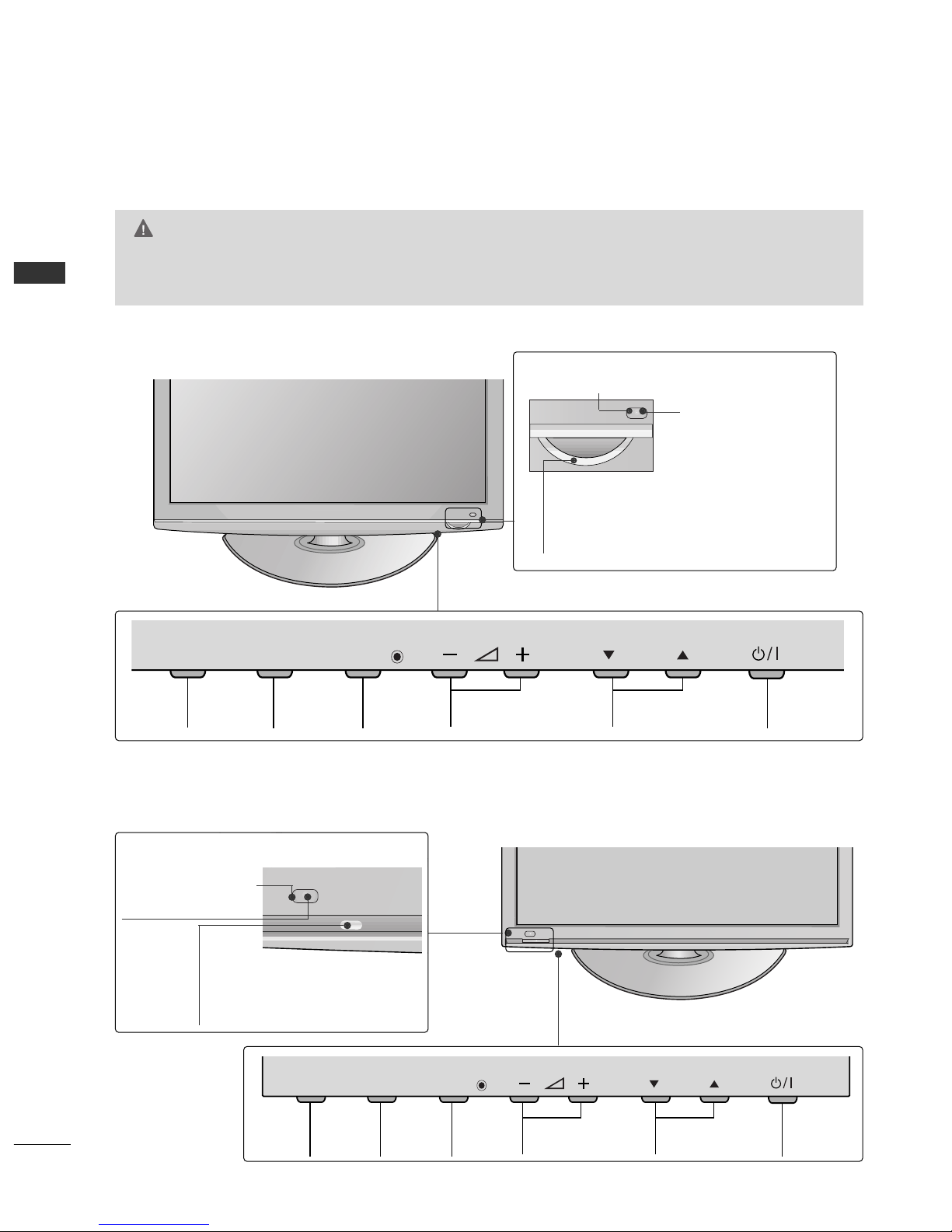
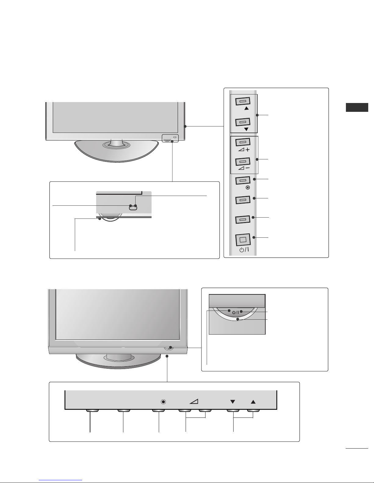
Front Panel Controls 4
Back Panel Information 6
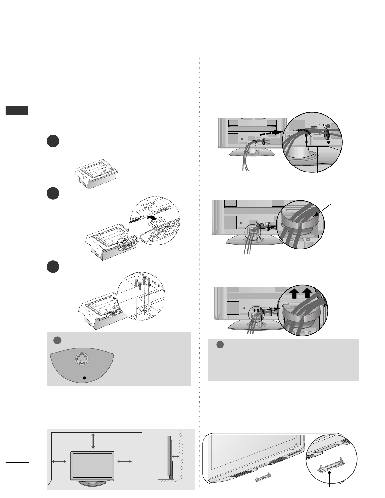
Stand Installation 8
Back Cover for Wire Arrangement 8
Desktop Pedestal Installation 8
Careful installation advice 9
Wall Mount: Horizontal Installation 9
Antenna Connection 10
Swivel Stand 10
EXTERNAL EQUIPMENT SETUP
HD Receiver Setup 11
DVD Setup 13
VCR Setup 16
Insertion of CI Module 19
Digital Audio Out Setup 19
Other A/V Source Setup 20
Usb Setup 20
PC Setup 21
- Screen Setup for PC Mode 24
WATCHING TV / PROGRAMME CONTROL
Remote Control Key Functions 28
Turning on the TV 32
Initializing setup 32
Programme Selection 32
Volume Adjustment 32
Quick Menu 33
On-Screen Menus Selection and Adjustment 34
Auto Programme Tuning 35
Manual Programme Tuning (In Digital Mode) 36
Manual Programme Tuning (In Analogue Mode) 37
Programme Edit 39
Software Update 42
Diagnostics 43
CI[COMMON INTERFACE] INFORMATION 44
Selecting the Programme Table 45
Input List 46
47
Data Service 49
Input Label 49
AV Mode 50
Simple manual 51
Initializing (Reset to original factory settings) 52
TO USE A USB DEVICE
When connecting a USB device 53
Photo List 54
Music List 58
Movie List 61
DivX Registration Code 65
Deactivation 66
EPG (ELECTRONIC PROGRAMME
GUIDE) (IN DIGITAL MODE)
- Switch on/off EPG 67
- Select Programme 67
- Button Function in NOW/NEXT Guide Mode 68
- Button Function in 8 Day Guide Mode 68
- Button Function in Date Change Mode 69
- Button Function in Extended Description Box 69
- Button Function in Record/Remind Setting Mode 70
- Button Function in Schedule List Mode 70
PICTURE CONTROL
Picture Size (Aspect Ratio) Control 71
ENERGY SAVING / POWER SAVING 73
Preset Picture Settings
- Picture Mode-Preset 74
Manual Picture Adjustment
- Picture Mode-User option 75
Picture Improvement Technology 76
Expert Picture Control 78

CONTENTS
3
Picture Reset 81
Image Sticking Minimization (ISM) Method 82
Demo Mode 83
Mode Setting 84
SOUND & LANGUAGE CONTROL
Auto Volume Leveler 85
Preset Sound Settings - Sound Mode 86
Sound Setting Adjustment -User Mode 87
SRS TruSurround XT 87
Clear Voice II 88
Balance 88
TV Speakers On/ Off Setup 89
Selecting Digital Audio Out 90
Audio Reset 91
Audio description 92
I/II
- Stereo/Dual Reception (In Analogue Mode Only) 93
- NICAM Reception (In Analogue Mode Only) 94
- Speaker Sound Output Selection 94
On-Screen Menu Language/Country Selection 95
Language Selection (In Digital Mode only) 96
TIME SETTING
Clock Setup 97
Auto On/ Off Timer Setting 98
Sleep Timer Setting 99
PARENTAL CONTROL /34
RATINGS
Set Password & Lock System 100
Block Programme 101
Parental Control 102
Input Block 103
Key Lock 104
TELETEXT
Switch on/off 105
SIMPLE Text 105
TOP Text 105
FASTEXT 106
Special Teletext Functions 106
DIGITAL TELETEXT
Teletext within Digital Service 107
Teletext in Digital Service 107
APPENDIX
Troubleshooting 108
Maintenance 110
Product Specifications 111
IR Codes 113
External Control Device Setup 115

PREPARATION
4
PREPARATION
FRONT PANEL CONTROLS
■
Image shown may differ from your TV
42/50PQ10**, 42/50PQ20**, 50PS20**
PROGRAMMEVOLUMEMENU OKINPUT POWER
P
MENUMENU
INPUTINPUT OKOK
OKMENUINPUT
P
MENU
INPUT OK
VOLUME PROGRAMME POWER
P
MENUMENU
INPUTINPUT OKOK
CH
VOL
MENU
INPUT ENTER
Power/Standby Indicator
Illuminates red in standby mode
Illuminates blue when the TV is
switched on
Intelligent Sensor
Adjusts picture according
to the surrounding
conditions
Remote
Control
Sensor
P
MENU
INPUT OK POWER
42/50PQ11**, 42/50PQ30**, 50PS30**
P
MENU
INPUT OK POWER
Intelligent Sensor
Adjusts picture according
to the surrounding
conditions (Except for
42/50PQ11**)
Remote Control
Sensor
Power/Standby Indicator
• Illuminates red in standby mode
•
Illuminates blue when the TV is switched on
P
MENU
INPUT OK POWER
P
MENU
INPUT OK POWER
CAUTION
GWhen the TV cannot be turned on with the remote control, press the main power button on the TV
(When the power is turned off with the main power button on the TV, it will not be turned on with the
remote control )
(Except for 42/50PQ10**)

5
PREPARATION
42/50PQ60**, 50PS60**
60PS40**
PROGRAMMEVOLUMEMENU OKINPUT
P
-+
OK
MENU
INPUT
P
-+
OK
MENU
INPUT
Remote Control Sensor
POWER
Power/Standby Indicator
• illuminates red in standby mode
• illuminates green when the TV is
switched on
P
- +
OK
OK
MENU
MENU
INPUT
INPUT
Power/Standby Indicator
• Illuminates red in standby mode
• The LED is off while the TV remains on
Remote Control
Sensor
Intelligent Sensor
Adjusts picture accord-
ing to the surrounding
conditions
MENU
INPUT
OK
P
P
PROGRAMME
VOLUME
OK
MENU
INPUT
POWER
P
MENU
INPUT OK POWER

6
PREPARATION
PREPARATION
BACK PANEL INFORMATION
A
Image shown may differ from your TV
42/50PQ10**, 42/50PQ11**
Power Cord Socket
This TV operates on an AC power The voltage is
indicated on the Specifications page Never
attempt to operate the TV on DC power
OPTICAL DIGITAL AUDIO OUT
Connect digital audio to various types of equipment
Connect to a Digital Audio Component
Use an Optical audio cable
Euro Scart Socket (AV1/AV2)
Connect scart socket input or output from an
external device to these jacks
HDMI Input
Connect an HDMI signal to HDMI IN
RS-232C IN (CONTROL & SERVICE) PORT
Connect to the RS-232C port on a PC
This port is used for Service or Hotel mode
Antenna Input
Connect RF antenna to this jack
PCMCIA (Personal Computer Memory Card
International Association) Card Slot
Insert the CI Module to PPCCMMCCIIAACCAARRDD SSLLOOTT
(This feature is not available in all countries )
SERVICE ONLY PORT
1
2
3
4
5
6
7
8
USB IN
SERVICE ONLY
1
HDMI IN
USB IN
SERVICE ONLY
(CONTROL & SERVICE)
USB IN
USB IN
SER
SER
VICE ONL
VICE ONL
Y
7
8
3
2
64 5

7
PREPARATION
Power Cord Socket
This TV operates on an AC power The voltage is
indicated on the Specifications page Never
attempt to operate the TV on DC power
RGB/DVI Audio Input
Connect the audio from a PC or DTV
OPTICAL DIGITAL AUDIO OUT
Connect digital audio to various types of equipment
Connect to a Digital Audio Component
Use an Optical audio cable
Euro Scart Socket (AV1/AV2)
Connect scart socket input or output from an
external device to these jacks
HDMI Input
Connect an HDMI signal to HDMI IN Or DVI (VIDEO)
signal to HDMI/DVI port with DVI to HDMI cable
RGB Input
Connect the output from a PC
RS-232C IN (CONTROL & SERVICE) PORT
Connect to the RS-232C port on a PC
This port is used for Service or Hotel mode
Component Input
Connect a component video/audio device to
these jacks
Antenna Input
Connect RF antenna to this jack
PCMCIA (Personal Computer Memory Card
International Association) Card Slot
Insert the CI Module to PPCCMMCCIIAACCAARRDD SSLLOOTT
(This feature is not available in all countries )
USB Input
Connect USB storage device to this jack
Audio/Video Input
Connect audio/video output from an external
device to these jacks
S-Video Input
Connect S-Video out from an S-VIDEO device
1
2
3
4
5
6
7
8
9
10
11
12
R
VARIABLE AUDIO OUT
1
HDMI IN
HDMI/DVI IN
2
1
AV IN 3
L/MONO
R
AUDIO
VIDEO
S-VIDEO HDMI IN 3
USB IN
SERVICE ONLY
AV IN 3
L/
L/
MONO
MONO
R
AUDIO
AUDIO
VIDEO
VIDEO
S-VIDEO
S-VIDEO
HDMI IN 3
HDMI IN 3
USB IN
SERVICE ONLY
10
11
5
24
3
95 6 7 8
12
42/50PQ20**, 42/50PQ30**, 42/50PQ60**, 50PS20**,
50PS30**, 50PS60**, 60PS40**

8
PREPARATION
PREPARATION
BACK COVER FOR
WIRE ARRANGEMENT
■
Image shown may differ from your TV
After Connecting the cables as necessary, install
CABLE HOLDER as shown and bundle the cables
STAND INSTALLATION
1
2
3
Carefully place the TV screen side down on a cushioned
surface to protect the screen from damage
Assemble the TV as shown
Fix the 4 bolts securely using the holes in the
back of the TV
■Image shown may differ from your TV
When installing the wall-mounted unit, use the protection
cover Insert the PPRROOTTEECCTTIIOONN CCOOVVEERRinto the TV
until clicking sound
NOT USING THE DESK-TYPE STAND
protection cover
CABLE HOLDER
4 inches
4 inches 4 inches 4 inches
DESKTOP PEDESTAL INSTALLATION
For adequate ventilation allow a clearance of 4”
(10cm) all around the TV
GGWhen assembling the
stand, make sure to dis-
tinguish and assemble
the front and rear side of
the stand correctly
NOTE
!
FRONT
■
Image shown may differ from your TV
■
When assembling the desk type stand, check
whether the bolt is fully tightened (If not tight-
ened fully, the product can tilt forward after the
product installation ) If you tighten the bolt with
excessive force, the bolt can deviate from abrasion
of the tightening part of the bolt
Only 60PS40**
Install the CCAABBLLEE MMAANNAAGGEEMMEENNTT CCLLIIPPas shown
CABLE
MANAGE-
MENT CLIP
Hold the CCAABBLLEE MMAANNAAGGEEMMEENNTT CCLLIIPPwith both
hands and pull it upward
How to remove the ca le management clip
NOTE
!
GGDo not use the CABLE MANAGEMENT CLIP to
lift the TV
- If the TV is dropped, you may be injured or the
TV may be damaged
(Except for 60PS40**)

9
PREPARATION
CAREFUL INSTALLATION ADVICE
AYou should purchase necessary components to fix the
TV safety and secure to the wall from the market
APosition the TV close to the wall to avoid the pos-
sibility of it falling when pushed
AThe instructions shown below are a safer way to set
up the TV, by fixing it to the wall, avoiding the possi-
bility of it falling forwards if pulled This will prevent
the TV from falling forward and causing injury This
will also prevent the TV from damage Ensure that
children do not climb or hang from the TV
NOTE
!
G When moving the TV undo the cords first
G
Use a platform or cabinet strong and large
enough to support the size and weight of the TV
G
To use the TV safely make sure that the height of
the bracket on the wall and on the TV is the same
3
1
2
Use the eye-bolts or TV brackets/bolts to fix the
product to the wall as shown in the picture
(If your TV has bolts in the eyebolts, loosen then bolts )
* Insert the eye-bolts or TV brackets/bolts and
tighten them securely in the upper holes
Secure the wall brackets with the bolts on the
wall Match the height of the bracket that is
mounted on the wall
3Use a sturdy rope to tie the product for align-
ment It is safer to tie the rope so it becomes
horizontal between the wall and the product
A The TV can be installed in various ways such as on
a wall, or on a desktop etc
A The TV is designed to be mounted horizontally
Power Supply
Circuit reaker
EARTHING
Ensure that you connect the earth wire to prevent
possible electric shock If grounding methods are not
possible, have a qualified electrician install a separate
circuit breaker
Do not try to earth the TV by connecting it to tele-
phone wires, lightening rods or gas pipes
WALL MOUNT: HORIZONTAL
INSTALLATION
AWe recommend the use of a LG Brand wall mounting
bracket when mounting the TV to a wall
AWe recommend that you purchase a wall mounting
bracket which supports VESA standard
ALG recommends that wall mounting be performed by a
qualified professional installer
4 inches
4 inches
4 inches
4 inches
4 inches
NOTE
!
G Should Install wall mount on a solid wall perpendicular to
the floor
G Should use a special wall mount, if you want to install it to
ceiling or slanted wall
G The surface that wall mount is to be mounted on should
be of sufficient strength to support the weight of TV set;
e g concrete, natural rock, brick and hollow block
G Installing screw type and length depends on the wall
mount used Further information, refer to the instructions
included with the mount
G LG is not liable for any accidents or damage to property or
TV due to incorrect installation:
- Where a non-compliant VESA wall mount is used
- Incorrect fastening of screws to surface which may cause
TV to fall and cause personal injury
- Not following the recommended Installation method
AA
BB
Model VESA
(A *B) Standard
Screw Quantity
42PQ10**
50PQ10**
42PQ11**
50PQ11**
42PQ20**
50PQ20**
42PQ30**
50PQ30**
42PQ60**
50PQ60**
50PS20**
50PS30**
50PS60**
60PS40**
400 * 400
400 * 400
400 * 400
400 * 400
400 * 400
400 * 400
400 * 400
400 * 400
400 * 400
400 * 400
400 * 400
400 * 400
400 * 400
600 * 400
M6
M6
M6
M6
M6
M6
M6
M6
M6
M6
M6
M6
M6
M8
4
4
4
4
4
4
4
4
4
4
4
4
4
4
2
1
2
1

10
PREPARATION
PREPARATION
AV IN 3
L/MONO
R
AUDIO
VIDEO
S-VIDEO HDMI IN 3
USB IN
SERVICE ONLY
AV IN 3
L/MONO
R
AUDIO
VIDEO
S-VIDEO HDMI IN 3
USB IN
SERVICE ONLY
ANTENNA CONNECTION
AV IN 3
L/ MONO
R
AUDIO
VIDEO
S-VIDEO HDMI IN 3
USB IN
SERVICE ONLY
■For optimum picture quality, adjust antenna direction
■An antenna cable and converter are not supplied
■To prevent damage do not connect to the mains outlet until all connections are made between the devices
Multi-family Dwellings/Apartments
(Connect to wall antenna socket)
Single-family Dwellings /Houses
(Connect to wall jack for outdoor antenna)
Outdoor
Antenna
(VHF, UHF)
Wall
Antenna
Socket
RF Coaxial Wire (75 ohm)
Antenna
UHF
Signal
Amplifier
VHF
■In poor signal areas, to achieve better picture quality it may be necessary to install a signal amplifier to the
antenna as shown above
■If signal needs to be split for two TVs,use an antenna signal splitter for connection
SWIVEL STAND
After installing the TV, you can adjust the TV manually to the left or right direction by 20 degrees to suit your viewing position

11
EXTERNAL EQUIPMENT SETUP
HD RECEIVER SETUP
■To avoid damaging any equipment, never plug in any power cords until you have finished connecting all equipment
■This section on EXTERNAL EQUIPMENT SETUP mainly uses diagrams for the 42PQ30** models
■
Image shown may differ from your TV
Connecting with a component ca le
(Except for 42/50PQ10**, 42/50PQ11**)
1
2
Signal
480i/576i
480p/576p
720p/1080i
1080 p
Component
O
O
O
O
(50/60Hz only)
HDMI
X
O
O
O
(24Hz/30Hz/50Hz/60Hz)
■This TV can receive Digital RF/Cable signals without an external digital set-top box However, if you do receive
Digital signals from a digital set-top box or other digital external device, refer to the diagram as shown below
Connect the video outputs (Y, PB, PR)of the digital set
top box to the CCOOMMPPOONNEENNTT IINN VVIIDDEEOOjacks on the
TV
Connect the audio output of the digital set-top box to
the CCOOMMPPOONNEENNTT IINN AAUUDDIIOOjacks on the TV
Turn on the digital set-top box
(Refer to the owner’s manual for the digital set-top box )
Select CCoommppoonneennttinput source using the IINNPPUUTT
button on the remote control
2
3
4
1
(For 42/50PQ10**, 42/50PQ11**)
HDMI IN
HDMI OUT
Component to
HDMI adapter
CCoonnnneeccttiinngg wwiitthh aa ccoommppoonneenntt ttoo HHDDMMII aaddaapptteerr
* You can receive HD broadcasting by using
Component to HDMI adapter
(You can inquire and purchase Component to
HDMI adapter at Website or Market )

12
EXTERNAL EQUIPMENT SETUP
Connecting a set-top ox with an HDMI ca le
HDMI IN
HDMI/DVI IN
2
1
1
Connecting with an HDMI to DVI ca le
(Except for 42/50PQ10**, 42/50PQ11**)
HDMI IN
HDMI/DVI IN
2
1
12
Connect the digital set-top box to HHDDMMII//DDVVII IINN 11,
HHDDMMII IINN,, HHDDMMII IINN 22or HHDDMMII IINN 33jack on the
TV
Turn on the digital set-top box
(Refer to the owner’s manual for the digital set-top box )
Select HHDDMMII11, HHDDMMII22or HHDDMMII33input source using
the IINNPPUUTTbutton on the remote control
2
3
1
Connect the digital set-top box to HHDDMMII//DDVVII IINN 11
jack on the TV
Connect the audio output of the digital set-top box to
the AAUUDDIIOO IINN ((RRGGBB//DDVVII)) jack on the TV
Turn on the digital set-top box (Refer to the owner’s
manual for the digital set-top box )
Select HHDDMMII11input source using the IINNPPUUTTbutton
on the remote control
2
3
4
1
GGCheck that your HDMI cable is version 1 3 or higher
If the HDMI cables don’t support HDMI version 1 3, flicker-
ing or no screen display can result Please use the latest
cables that support at least HDMI version 1 3
NOTE
!

13
EXTERNAL EQUIPMENT SETUP
DVD SETUP
Connecting with a component ca le
(Except for 42/50PQ10**, 42/50PQ11**)
AV IN 3
L/MONO
R
AUDIO
VIDEO
S-VIDEO HDMI IN 3
Component Input ports
To achieve better picture quality, connect a DVD player to the component input ports as shown below
Component ports on the TV
YP
BPR
Video output ports
on DVD player
Y
Y
Y
Y
PB
B-Y
C
P
PR
R-Y
Cr
Pr
1
2
Connect the video outputs (Y, PB, PR)of the DVD to the
CCOOMMPPOONNEENNTT IINN VVIIDDEEOOjacks on the TV
Connect the audio outputs of the DVD to the
CCOOMMPPOONNEENNTT IINN AAUUDDIIOOjacks on the TV
Turn on the DVD player, insert a DVD
Select CCoommppoonneenntt input source using the IINNPPUUTT
button on the remote control
Refer to the DVD player's manual for operating instruc-
tions
2
3
4
5
1

14
EXTERNAL EQUIPMENT SETUP
(R) AUDIO (L)
AUDIO/
VIDEO
AV IN 3
L/MONO
R
AUDIO
VIDEO
S-VIDEO HDMI IN 3
1
2
3
4
1
Connecting with a Euro Scart ca le
Connect the Euro scart socket of the DVD to the AAVV11
Euro scart socket on the TV
Turn on the DVD player, insert a DVD
Select AAVV11input source using the IINNPPUUTTbutton on
the remote control
If connected to AAVV22Euro scart socket, select AAVV22
input source
Refer to the DVD player's manual for operating
instructions
NOTE
!
GGAny Euro scart cable used must be signal shielded
Scart
AV1
AV2
Input
Video Audio RGB
Output
Video, Audio
ATV only
ATV, DTV, AV1/2/3 output is available
OOO
OOX
Digital TV
Analogue TV
AV1/2/3
Component/RGB/HDMI
AV1
(TV Out)
XO O
OO O
OO O
OX O
AV2
(Monitor Out)
AV2
(When DTV scheduled recording is in
progress using recording equipment )
GGTV Out : Outputs analog
TV video signals
Monitor Out: Outputs the
current screen image
GG
AV3, Component, RGB :
Except for 42/50PQ10**,
42/50PQ11**
(The input mode is converted to
DTV automatically )
Output Type
Current
input mode

15
EXTERNAL EQUIPMENT SETUP
HDMI IN
HDMI/DVI IN
2
1
AV IN 3
L/MONO
R
AUDIO
VIDEO
S-VIDEO HDMI IN 3
Connecting the HDMI ca le
Connect the HDMI output of the DVD to the
HHDDMMII//DDVVII IINN 11,HHDDMMII IINN,, HHDDMMII IINN 22or HHDDMMII
IINN 33jack on the TV
Select HHDDMMII11, HHDDMMII22or HHDDMMII33input source using
the IINNPPUUTTbutton on the remote control
Refer to the DVD player's manual for operating
instructions
2
3
1
1
GGThe TV can receive video and audio signals simultaneously
when using a HDMI cable
GGIf the DVD does not support Auto HDMI, you must set the
output resolution appropriately
GGCheck that your HDMI cable is version 1 3 or higher
If the HDMI cables don’t support HDMI version 1 3, flicker-
ing or no screen display can result Please use the latest
cables that support at least HDMI version 1 3
NOTE
!
Connecting with a S-Video ca le
(Except for 42/50PQ10**, 42/50PQ11**)
AV IN 3V IN 3
L/MONOMONO
R
AUDIOAUDIO
VIDEOVIDEO
S-VIDEOS-VIDEO HDMIHDMI ININ 3
L R
S-VIDEOVIDEO
OUTPUT
SWITCH
ANT IN
ANT OUT
Connect the S-VIDEO output of the DVD to the SS--
VVIIDDEEOOinput on the TV
Connect the audio outputs of the DVD to the AAUUDDIIOO
input jacks on the TV
Turn on the DVD player, insert a DVD
Select AAVV33input source using the IINNPPUUTTbutton on
the remote control
Refer to the DVD player's manual for operating instruc-
tions
2
3
4
5
1
12

16
EXTERNAL EQUIPMENT SETUP
VCR SETUP
■To avoid picture noise (interference), allow adequate distance between the VCR and TV
AV IN 3
L/MONO
R
AUDIO
VIDEO
S-VIDEO HDMI IN 3
AV IN 3
L/MONO
R
AUDIO
VIDEO
S-VIDEO HDMI IN 3
OUTPUT
SWITCH
ANT IN
R
S-VIDEO VIDEO
ANT OUT L
Wall Jack
Antenna
1
2
Connecting with a RF Ca le
EXTERNAL EQUIPMENT SETUP
Connect the AANNTT OOUUTTsocket of the VCR to the AANNTTEENNNNAA IINNsocket on the TV
Connect the antenna cable to the AANNTT IINNsocket of the VCR
Press the PPLLAAYYbutton on the VCR and match the appropriate channel between the TV and VCR for
viewing
2
3
1

17
EXTERNAL EQUIPMENT SETUP
(R) AUDIO (L)
AUDIO/
VIDEO
AV IN 3
L/MONO
R
AUDIO
VIDEO
S-VIDEO HDMI IN 3
AV IN 3
L/MONO
R
AUDIO
VIDEO
S-VIDEO HDMI IN 3
Connecting with a Euro Scart ca le
1
Connect the Euro scart socket of the VCR to the AAVV11
Euro scart socket on the TV
Insert a video tape into the VCR and press PLAY on
the VCR (Refer to the VCR owner’s manual )
Select AAVV11input source using the IINNPPUUTTbutton on
the remote control
If connected to AAVV22 Euro scart socket, select AAVV22
input source
2
3
4
1
NOTE
!
GGAny Euro Scart cable used must be signal shielded
Scart
AV1
AV2
Input
Video Audio RGB
Output
Video, Audio
ATV only
ATV, DTV, AV1/2/3 output is available
OOO
OOX
Digital TV
Analogue TV
AV1/2/3
Component/RGB/HDMI
AV1
(TV Out)
XO O
OO O
OO O
OX O
AV2
(Monitor Out)
AV2
(When DTV scheduled recording is in
progress using recording equipment )
(The input mode is converted to
DTV automatically )
Output Type
Current
input mode
GGTV Out : Outputs analog
TV video signals
Monitor Out: Outputs the
current screen image
GG AV3, Component, RGB :
Except for 42/50PQ10**,
42/50PQ11**

18
EXTERNAL EQUIPMENT SETUP
GGIf both S-VIDEO and VIDEO sockets have been connected to
the S-VHS VCR simultaneously, only the S-VIDEO can be
received
NOTE
!
AV IN 3V IN 3
L/MONOMONO
R
AUDIOAUDIO
VIDEOVIDEO
S-VIDEOS-VIDEO HDMIHDMI IN 3
LR
S-VIDEO VIDEO
OUTPUT
SWITCH
ANT IN
ANT OUT
AV IN 3
L/MONO
R
AUDIO
VIDEO
S-VIDEO HDMI IN 3
Connecting with a S-Video ca le
(Except for 42/50PQ10**, 42/50PQ11**)
Connect the S-VIDEO output of the VCR to the SS --
VVIIDDEEOOinput on the TV set The picture quality is
improved; compared to normal composite (RCA cable)
input
Connect the audio outputs of the VCR to the AAUUDDIIOO
input jacks on the TV
Insert a video tape into the VCR and press PLAY on the
VCR (Refer to the VCR owner’s manual )
Select AAVV33input source with using the IINNPPUUTTbutton on
the remote control
2
3
4
1
12
Connecting with a RCA ca le
(Except for 42/50PQ10**, 42/50PQ11**)
AV IN 3
L/MONO
R
AUDIO
VIDEO
S-VIDEO HDMI IN 3
AV IN 3V IN 3
L/MONO
R
AUDIOAUDIO
VIDEOVIDEO
SS-VIDEO HDMI IN 3
LR
S-VIDEO
VIDEO
OUTPUT
SWITCH
ANT IN
ANT OUT
Connect the AAUUDDIIOO/VVIIDDEEOOjacks between TV and
VCR Match the jack colours (Video = yellow, Audio Left
= white, and Audio Right = red)
Insert a video tape into the VCR and press PLAY on
the VCR (Refer to the VCR owner’s manual )
Select AAVV33input source using the IINNPPUUTTbutton on
the remote control
1
2
3
GGIf you have a mono VCR, connect the audio cable from the
VCR to the AAUUDDIIOO LL//MMOONNOOjack of the TV
NOTE
!
1
This manual suits for next models
17
Other LG Plasma TV manuals