LG GF-50712 Series User manual

1
GF-50712**
GR-J24F****
REFRIGERATOR
SERVICE MANUAL

Chapter 1 Safety Warning and Cautions ..........................................................................................3
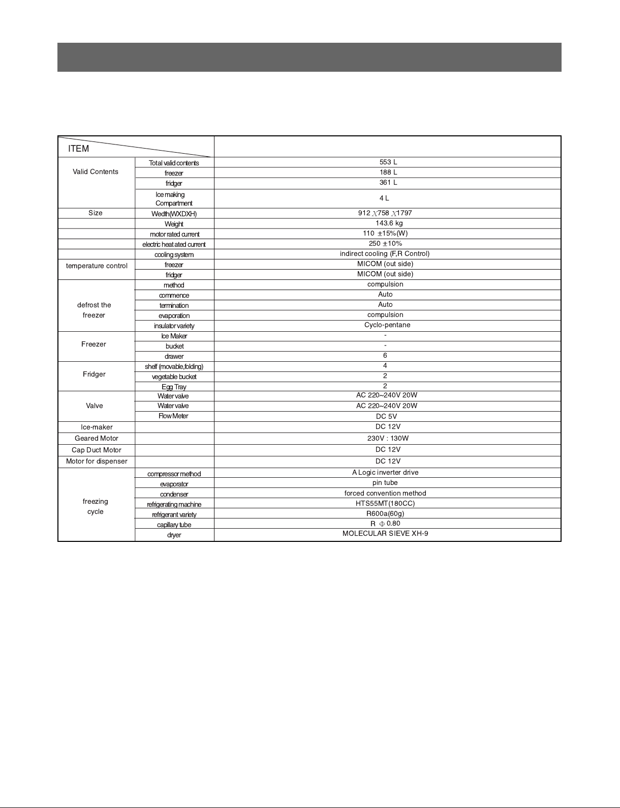
Chapter 2 Product Standards ...........................................................................................................8
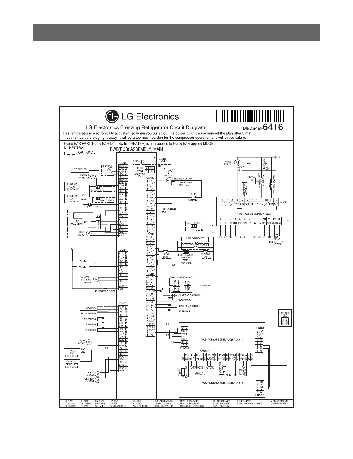
Chapter 3 Circuit Diagram ...............................................................................................................10
Chapter 4 Appearance Size of Refrigerator and Name of Every Part .........................................11
1. Appearance Size of Refrigerator ...............................................................................................11
2. Major Names ............................................................................................................................12
Chapter 5 Micom Function...............................................................................................................13
1. Operating panel drawing ..........................................................................................................13
2. Function description .................................................................................................................14
Chapter 6 PCB Picture......................................................................................................................21
Chapter 7 Trouble Shooting.............................................................................................................23
1. Error code summary .................................................................................................................23
2. Function description .................................................................................................................24
Chapter 8 Description of MICOM circuit. .......................................................................................45
1. Under/Overcooling compensation circuit of refrigerator ............................................................45
2. Undercooling compensation circuit of freezer ..........................................................................46.
3. Sensor resistance characteristics table ....................................................................................48
Chapter 9 COMPRESSOR ...............................................................................................................49
1. How to judge A-inverter linear compressor error ......................................................................49
Chapter 10 How to replace doors ...................................................................................................74
1. Removing and Replacing Refrigerator Doors ...........................................................................74
Chapter 11 How to service the refrigerator home bar ..................................................................78
1. Family Home bar Model ...........................................................................................................78
How to replace Reed Switch......................................................................................................81
2. Wide Home bar Model...............................................................................................................82
3. Pillar disassembly and assembly...............................................................................................82
Chapter 12 How to replace refrigerator Cover TV Assembly .......................................................83
1. Cover TV service method .........................................................................................................83
Chapter 13 How to disassemble refrigerator Multi Duct Assembly ............................................84
1. Multi duct service method .........................................................................................................84
Chapter 14 How to adjust the refrigerator door level difference .................................................85
1. When the door height is different ..............................................................................................85
Chapter 15 How to adjust the door front and rear level difference .............................................86
1. When the bottom part of refrigerator door unleveled ................................................................86
2. When the bottom part of freezer door unleveled .....................................................................86
Chapter 16 How to Replace Water Valve & Fan .............................................................................87
Chapter 17 Heavy Repair Method of Refrigerator with R600a Refrigerant .................................89
1. Outline ......................................................................................................................................89
2. Heavy repair SVC method ........................................................................................................90
2
Table of Contents
Chapter 18 Exploded view ..........................................................................97

3
Safety Warning and Cautions
'Cautions for safety should be observed since they are for previously prevent accidents and
dangers when properly use or repair products in a safe manner.
Cautions are classified into Warning and Caution and meaning of them are as follows
Warning
Warning
Warning means symbol to inform any accidents that may result in large danger such
as death or severe injury,etc when violating instructions.
Caution
Caution means symbol to inform any accidents that may result in injury or physical
damage of houses or furniture,etc when violating instructions.
Be cautions of air ventilation in case of repairing refrigerator cycle.
Remove heat source or fire appliance for working since R600a
refrigerant is inflammable. (Absolute no-smoking)
Be cautious of electric shock.
Control board uses power supply of
about 310V.
During the replacement of PWB
parts,make sure to pull out
the power plug and wait for
at least 3 min.,and first
pull out the power plug before
replacing or repairing other electric parts.
Check that power plugs are not
pressed by the rear side of
refrigerator.
Damage of power
plugs could result in
fire or electric shock.
Do not allow consumers to directly
repair,disassemble or modify
refrigerator.
Harm,electric shock
or fire could occur.
Use dedicate socket for power
socket.
Inserting various products
into a power socket at the
same time for use could
result in fire due to
overheat of the socket part.
Chapter 1 Safety Warning and Cautions

Inputting products requiring strict temperature
control may result in change
of quality or
dangerdue to
unexpected
reaction.
4
Safety warnings and cautions
If grounding is required,be sure to
perform grounding.
Be sure to perform grounding if deemed there
is danger of
electric shock
by water or
moisture.
Do not allow to store inflammable
ether, benzene, alcohol, chemical
drugs, LP gas, etc in a refrigerator.
There is danger of
explosion and fire.
Ether
Benzene
LPgas
Do not allow to keep drugs or
academic data, etc.in a refrigerator.
DRUG
academic
data
When getting refrigerator away,
remove its door
and do not leave
refrigerator at a place
where children play.
If children go in it and are
entrapped in it,it is
dangerous.
Take power plugs from socket for
cleaning or repair.In addition,plug
out or plug in with the wet hands.
Electric shock or
harm may occur.
Firstly take power socket out for
replacement of indoor lamp.
Electric shock may occur.
Check that dusts are adhered to the
power socket and securely insert
plugs by the end of pin so that
shaking may not occur.
Dust or incomplete connection
may result in fire.
When dusts etc are stained to the
pin part of the power socket,cleanly
wipe out them.
Fire may occur.
Warning
Grounding nut
Grounding wire
More than
75cm
Copper
plate

5
Safety warnings and cautions
Do not expand or modify length of
power plugs to use.
Electric shock or fire
may occur due to
electrical damage of
power cables.
Do not place heavy objects on a
refrigerator.
Dropping of objects during
opening or closing doors
may cause injury.
Do not hang to the door of a
refrigerator.
The refrigerator may fall
down or the hands may be
held between doors and
damaged.Especially,
be cautious of children.
Do not use an inflammable spray
near a refrigerator.
There is danger of fire since
it is inflammable material.
Leave fire appliances at a remote
location.
There is danger of fire.
Do not touch a refrigerator or socket
when gas leaks and open the door
for ventilation.
There is danger of
burning due to
explosion and
sparking.
Do not spray water inside or outside
of the refrigerator.
Bad insulation of electrical
part may result in electric
shock or fire.
Do not use a refrigerator for other
purpose than for home purpose
(keeping of medical drugs or
experimental materials,
for vessel)
Unexpected danger
such as fire,electric
shock or deterioration
of objects kept.
Always use inundated
refrigerator after service.
Electric shock or fire may occur.
Warning

6
Safety warnings and cautions
Do put the vessel that flower
base,cup,cosmetics or
drugs,etc are contained
on the refrigerator.
Fire or electric shock may occur,or
injury due to dropping may occur.
Do not accumulate objects on a
refrigerator or do not keep
foods in random method.
Dropping of objects when
opening or closing the door may
cause physical injury.
Do not put bottles,etc in the freezing
room.
There is injury danger due
to icing and breaking of
contents.
Be sure to rated parts for
replacement of electric parts.
Check marking of model,rated
voltage,rated current,operation
temperature,etc of electrical parts.
Accurately arrange wiring of the
housing part for failure repair.
Check that the hanging part
of the housing part is firmly
suspended.
Do not damage,process or forcedly
bend,take out or twist power cords.
Damage of power cords may
cause fire or electric shock.
Entirely remove dusts or foreign
materials from housing part,wiring
part and checking part,etc
for failure repair.
Danger of fire can be
prevented from
tracking,short,etc.
Check assembling status of parts
after failure repair.
Parts should show same status
before repair.
Check that there is a track that
moisture is penetrated into electric
parts.
If there is a track that moisture is
penetrated,replace parts or take a necessary
step such as insulation tapping.
Insert power plug into a socket after
more than 3 minutes pass when
taking out plugs and then
inserting them again.
Unreasonable operation of a
compressor may cause failure.
Caution

7
Safety warnings and cautions
While you pull out the power
plugs,hold the end of the plug,not
the cord.
Fire may occur due to electric
shock or short-circuit.
Do not use power cords or power
plugs when they are damaged or
holes of power plugs are loose.
Fire may occur due to electric
shock or short-circuit.
Take power plugs from the socket
when not using them for a long time.
Electric shock,electrical leakage
or fire may occur due to weaken
insul ati on.
Install the product at the place where
the floor is strong and horizontal.
If installing the product at
unstable place,the refrigerator
may upset due to closing or
opening of doors of refrigerator
and user may be damaged.
Do not install product at a place with
much moisture and where water
spatters.
Deterioration of insulation
may cause electrical
leakage.
Transport product catching with
handles on the bottom side and the
top side when transporting.
If not catching with handles,
you can be damaged since
the hands are slipped.
Do not touch foods or vessels (made
of metal)in the freezing room with
the wet hands.
You may be frostbitten.
Be careful when opening or closing
refrigerator door since a person near
the refrigerator may be injured.
Be cautious since the hands or
foots are lay between door gaps
and children beside the doors
may be damaged by the corners
of product.
Do not put the hands under the
bottom of the refrigerator.
The bottom side of the
refrigerator is made of iron plate
and so you may be damaged.
Do not put live animals in the
refrigerator.
Caution

8
Product Standard
Chapter 2 Product Standard
Totalvalid contents
freezer
f
Ice making
ompartment
ridger
Wedth(WXDXH)
Weight
motor rated current
electric heat ated current
cooling system
freezer
fridger
method
commence
termination
evaporation
insulator variety
Ice Maker
bucket
drawer
shelf (movable,folding)
vegetable bucket
Egg Tray
compressor method
evaporator
condenser
refrigerating machine
refrigerant variety
capillary tube
dryer
ITEM
553 L
188 L
361 L
4L
912 758 1797
143.6 kg
110 15%(W)
250 10%
indirect cooling (F,R ontrol)
MI OM (out side)
MI OM (out side)
compulsion
Auto
Auto
compulsion
yclo-pentane
-
-
6
4
2
2
A Logic inverter drive
pin tube
forced convention method
HTS55MT(180 )
R600a(60g)
R0.80
MOLE ULAR SIEVE XH-9
Valid ontents
Size
temperature control
defrost the
freezer
Fridger
Water valve
Water valve
Flow Meter
A 220~240V 20W
A 220~240V 20W
D 5V
Valve
D 12V
Ice-maker
230V : 130W
Geared Motor
D 12V
ap Duct Motor
D 12V
Motor for dispenser
freezing
cycle
Freezer

9
Product Standard
Home bar Door Switch
Main Fuse
Power cord
overload device
freezer fan motor
cooling compressor fan motor
Hygiene fan motor
first defroster
defroster period
break period
defroster sensor
temperature fuse
(rating/operation)
Heater Sheath/
Heater L-cord
ap duct heater
fridger hombar heater
freezer homebar heater
Dispenser heater
Pillar heater
driving
multi drawer corner
Side
bacteriostatic filter
To p
Side
fridger
freezer
freezer 7hours ~ 50hours (Vary depending on the conditions of use)
freezer 7mins
freezeer 5 (Vary depending on the conditions of use)
250V / 10A / 72
A 240V ( freezer : 250W )
D 12V / 3W
A 240V/6W
A 240V/7.1W
Not use
D 12V/1W 2EA
Beta duct heater D 12V / 1W
Icing fan heater A 240V / 9W
Water pipe heater D 12V / 0.8W
MRA12362-9201
D 13V
D 13V
Icing Fan motor D 13V
D 12V/1.3W
D 12V/2.16W
D 12V/0.25W
D 12V/3.6W
D 5V/2.16W
5V/2.5mA
D 5V/2.5mA
5V/2.5mA
-
250V 7.5A, 10A KO E-3 0.75
defroster
component
dew formation
prevention
component
ompressor
capacitor
de-icing
element
freezer lamp
fridger lamp
Door Switch
electric
part
standa
rd
freezer 4hours (Vary depending on the conditions of use)

10
Circuit Diagram
Chapter 3 Circuit Diagram

11
Appearance Size of Refrigerator and Name of Every Part
Chapter 4 Appearance Size of Refrigerator and Name of Every Part
1. Appearance Size of Refrigerator
(Unit : mm)
Front View
Plane View
Width
Depth
Height
Minimum air
circulation
space
Width(A)
When opening door by 90 (including handle/button) (B)
Case (including back handle) (C)
After disassembling door (including hinge, L) (D)
Including door (not including handle) (E)
Including handle/button (F)
When opening door by 90 (G)
Cabinet (H)
Including Cover PCB (J)
Including door (K)
Top part
Side part
Rear part
912
1019
631
698
775
758
1118
1750
1797
1785
300
20
50

12
Appearance Size of Refrigerator and Name of Every Part
2. Major Names
Cover Hinge
Home Bar
Back
Handle
Cover PCB
*The appearance and specifications of the actual product may differ depending on the model.

13
Micom Function
Chapter 5 Micom Function
1. Operating panel drawing (Applied display is different for each model)
First
power on
Classification
NOTCH
Freezer set
temperature
3
-18
4
-19
Press
1 time
Press
2 time
Press
3 time
Press
4 time
Press
5 time
Press
6 time
Press
7 time
Press
8 time
5
-20
6
-21
7
-22
8
-23
9
-24
1
-16
2
-17
4NOTCH
Freezer set
temperature 32
5
1
6
0
7
6
1
5
2
4
3

14
Micom Function
2-1-1. Back light control
1. When the applianc e is plugged in,it is set to 3 for Refrigerator and -18 for Freezer. You can adjust the
Refrigerator and the Freezer control temperature by pressing the ADJUST button.
2. When the power is initially applied or restored after power failure,it is set to Control temperature Previously.
3. If you do not press any button after turning on the power,only CRUSH or CUBE or WATER LED that has been
selected will be turned on and all other LEDs on the display Panel will be turned off within 60 seconds. (Power
Save Mode)
4. If you press a button, only CRUSH, CUBE,WATER LEDs that has been selected will be turned on and all other
LEDs on the display Panel will be turned off within 20 seconds. (Power Save Mode)
2-1-2. Touch button function
1. The touch button is a static electricity (Capacitive) switch and responds to any close body contact or object with
capacitance within a certain distance even when terminal is not directly exposed.
2. When you touch the top central part of the touch button label, the display button will respond.
3. When cleaning the front panel or when any part of the human body touches the touch button, the switch can be
operated.
4. If there is any alien substance on the button or if the touch button is operated by objects other than human body
part such as cloth or glove, the button may not be operated depending on the material or thickness of the object.
2-1-3. Lock function (Display button lock)
1. When the refrigerator is first turned on,the buttons are not locked.
2. To lock the display and the control panel,press and hold LOCK button for 3 seconds.
“LOCK ” is activated with “Lock Icon ” on after Unlock Icon Blinking 2 times.
3. The LOCK button is the only control feature that remains active in the locked state.
The buzzer sound and other control buttons are deactivated.
4. To release from the locked state,press and hold the LOCK button again for 3 seconds.
“LOCK ” is deactivated whit “Unlock Icon ” on after Lock Icon Blinking 2 times.
2. Function description
2-1. function of LCD/LED/Magic display panel

15
2-1-4. Water Filter condition display function
1. 1.There is a replacement indicator light for the water
filter cartridge on the dispenser.
2. Water filter needs replacement once six months or of
using water filter.
3. When the Water Filter Icon on,you must exchange the
filter.
4. After replacing the filter,press and hold the Water Filter
button for more than 3 seconds.After then Water Filter
icon turn off with reset status.
In initial Power On
/ Filter RESET
Icon ON
Filter Status
Display
Classification
2-1-5. How to operate the Hygiene fresh filter
Pure N Fresh
:Press the “Pure N Fresh ”
Button to select Auto,Power,Off
Micom Function

16
2-1-6. Hygiene Filter replacement condition display function
1. There is a replacement indicator light for the Hygiene filter cartridge .
2. Hygiene filter in OFF Mode needs replacement once 24 months.
3. Hygiene filter in Auto Mode or Power Mode needs replacement once 12 months
4. When the Hygiene Filter Reset icon on,you must exchange the filter.
5. After replacing the filter,press and hold the Pure N Fresh button for more than 3 seconds.After then Hygiene Filter Reset
icon turn off with reset status.
1. Fan installed on the multi.duct on the rear side of the filter operates.
2. Fan is repeatedly turned on for 10 minutes and then off for 60 minutes.
3. If the R-door is opened while the fan is operating,the fan will be turned off,and when the R-door is closed,the fan will be
turned on.
4. LED near the filter installed on the multi duct is turned on when the R -door is opened and off when closed .
(LED is always turned off in OFF mode)
Filter RESET
in OFF Mode Icon ON
Filter Status
Display
Classification
2-1-6-1. AUTO Mode
1. Fan installed on the multi.duct on the rear side of the filter operates.
2. Fan is repeatedly turned on for 10 minutes and then off for 5 minutes for 4 hours,and then automatically switches over to
AUTO Mode.
3. If the R -door is opened while the fan is operating,the fan will be turned off,and when the R -door is closed,the fan will be
turned on.
4. LED near the filter installed on the multi duct is turned on when the R -d oor is opened and off when closed.
(LED is always turned off in OFF mode)
2-1-6-2. POWER Mode
1. You can select water,cube,crush by dispenser button.
2. When you press dispenser button,dispenser menu will be
changed.(crush water cube ).
3. If you press dispenser pad with holding your cup in the dispenser
,water or ice will be dropped into your cup.
4. when after initially establishing the water comes out,the water tank
inside fills and until at the time of quality the hour is caught.
2-1-8. Dispenser use selection
1. You can set Ice Maker ON or OFF by Ice Maker ON/OFF button.
2. If you press and hold the button for 3 seconds,the state of Ice Maker will be
changed (OFF ON,ON OFF).
3. If you set Ice Maker OFF,Ice Maker does not make Ice anymore.(but dispenser
auger moter will work).
2-1-9. Ice Maker ON/OFF selection
1. Please select Express Freezing function for quick freezing.
2. When you press the Express Freezing button, the Express Freezing icon will be turned
on again.
3. Express Freezing function automatically turns off after a fixed time passes.
2-1-7. How to operate the Express Freeze function
Micom Function
Filter RESET
in Auto Mode Icon On Filter RESET
in Power Mode Icon ON
Dispenser
button
Dispenser
PAD

17
Micom Function
1. The purpose of this function is to intensify the cooling speed of freezer and to increase the amount of ice.
2. Whenever selection switch is pressed, selection/release, the Icon will turn ON or OFF.
3. If there is a power outage and the refrigerator is powered on again, Ice PLUS will be canceled.
4. To activate this function, press the Ice PLUS key and the Icon will turn ON. This function will remain
activated for 24 hrs.
The first 30 minutes the compressor, Freezer Fan and Icing Fan will be ON. The next 23 hours 30
minutes the Ice room will be controlled at the Ice room lowest temperature. After 24 hours or if the Ice
PLUS key is pressed again, the Ice room will return to its previous temperature.
5. During the 30 minutes :
(1) Compressor, Freezer Fan and Icing Fan run continuously.
(2) If a defrost cycle begins during the first 15 minutes of Ice Plus, the Ice PLUS cycle will complete its cycle
after defrosting has ended. If the defrost cycle begins when Ice Plus has run for more than 20 minutes,
Ice PLUS will run for 40 minutes after the defrost is completed.
(3) If Ice PLUS is pressed during defrost, Ice Plus Icon is on but this function will start 7 minutes after
defrost is completed.
(4) If Ice Plus is selected within seven minutes after compressor has stopped, the compressor (compressor
delays seven minutes) shall start after the balance of the delay time.
6. For the rest of the 23 hours 30 minutes, the Ice room will be controlled at the lowest temperature.
1. To increase cooling speed and load response speed, MICOM variably controls freezing room fan motor at the high
speed of RPM and standard RPM.
2. MICOM only operates in the input of initial power or special freezing operation or load response operation for the high
speed of RPM and operates in the standard RPM in other general operation.
3. If opening doors of freezing /cold storage room or home bar the freezing room fan motor OFF.(12 ~20 seconds)
4. As for monitoring of BLDC fan motor error in the freezing room, MICOM immediately stops the fan motor by
determining that the BLDC fan motor is locked or poor if there is no position signal for more than 65 seconds at the
BLDC motor, it will see it as BLDC Fan motor locked for fan motor defect and immediately stops the fan motor, and
displays error in the refrigerator display
(refer to the failure diagnosis function table) and periodically performs ON/OFF.
2-2. Express freezing
2-3. Control of variable type of freezing room fan
1. The M/C room fan motor performs ON/OFF control by linking with the COMP.
2. The fan motor in the machine room operates in a high / medium / low speed RPM depending on the ambient
lemperature and humidity.
3. Failure sensing method is same as in fan motor of freezing fan motor
(refer to failure diagnosis function table for failure display).
2-4. Control of M/C room fan motor
1. The Icing Fan is controlled by the the sensor on the top of the ice compartment.
2. The Failure sensing method is the same as in the fan motor of the freezer
2-5. Control of Ice Compartment Fan

18
Micom Function
1. Buzzer generates alarm sound if doors are not closed even when more than a minute consecutively has passed
with doors of freezing / cold storage room or home bar opened.
2. Buzzer rings three times in the interval of 0.5 second after the first one-minute has passed after doors are opened
and then repeats three times of On/Off alarm in the cycle of every 30 seconds.
3. If all the doors of freezing / cold storage room or home bar are closed during door open alarm, alarm is immediately
released.
2-6. Door opening information
1. If pressing the front display button, Ding ~ sound rings.
2-7 Ringing of button selection buzzer
1. If pressing the test button in the main PCB, Phi ~ sound rings.
2. In selecting compulsory operation, alarm sound is repeated and completed in the cycle of On for 0.2 second and
Off for 1.8 second three times.
3. In selecting compulsory frost removal, alarm sound is repeated and completed in the cycle of On for 0.2 second,
Off for 0.2 second, On for 0.2 second and Off for 1.4 second three times.
2-8. Ringing of compulsory operation, compulsory frost removal buzzer
1. Defrost will be operated when the total time of compressor operation reaches at 7~50 hours.
2. Defrost will finish when the sensor temperature goes up to 5 degrees after starting defrost. If the temperature of
defrost sensor does not reach to 5 degrees until the maximum defrost time, which is 60 minutes, and that case is
Repeat 2 times, display shows error code of defrosting.
3. Defrost will not be operated when defrost sensor defected (disconnection or short circuit).
2-9. Defrost (removing frost) function
Doors of freezing / cold storage room or home bar
Closed opened
within 1 min. 1 min.
3 times
30sec
closed closedopened
BUZZER
3 times 3 times 3 times
30sec 30sec

19
Micom Function
1. Failure diagnosis function enables easy SVC when a defect affecting the performance of the product occurs during
the use of the product.
2. When a failure occurs, even if function adjustment button is pressed, it does not perform the function.
3. While error code is displayed due to failure, if the failure is cured, it returns to normal state.
(Rest)
4. Error code is displayed on the F-Room set temperature display part and R-Room set temperature display part in
the LCD of the refrigerator display part. All LCD graphics other than the error code will be turned off.
*Display check function:If simultaneously pressing Express Freeze button and Freezer temperature adjustment
button for a second,display LCD graphics on.If releasing the button,the LCD graphic displays the previous
status.You can check the error code Within 3 -hour Period from initial error
2-10. Failure Diagnosis Function
1. Make the display locked state, open R-room door, and place the phone near the speaker hole at the top right. Long
press freezing temperature button to start smart diagnosis.
- If the display is already in locked state, long press the lock button to release lock, and long press the lock button
again to make it locked state.
- Check if the speaker side of the phone(microphone) is toward the speaker hole.
- After making the phone to be toward the speaker hole, press down the freezing temperature button until the
display screen is turned off.
2. Do not take away the phone while data is being transmitted.
- During the data transmission for smart diagnosis, wait with the phone placed on the speaker hole at the top right.
The remaining time for data transmission will be displayed on the display screen.
3. After completing the data transmission, listen to the smart diagnosis result from the consultant.
- When the data transmission is completed, the refrigerator will be turned off and on automatically in a few seconds
with the transmission completed message. Listen to the result of the analyzed diagnosis from the consultant and
take actions.
2-11. Smart Diagnosis(only for applied model)-
Use this if there is an abnormal action or failurein the
refrigerator and when you want to contact the service center and receive precise diagnosis.
Use it only when the consultant is on line and do not run it in normal time.

20
Micom Function
2-12. Refrigerator LCD/LED/Magic Display demo function
1. The demo function of the refrigerator automatically runs on the refrigerator on exhibit to show how to operate and
use the LCD/LED/Magic Display function, and while this function is running, only the lamp and ice maker
operates.
2. To start the demo function on the refrigerator, open the refrigerator door and while keeping the temperature button
pressed, press the Express Freezing button 3 times until function starts with the Ding Ding Ding sound. To
cancel the demo function, repeat the same procedure of opening the refrigerator door and while keeping the
temperature button pressed, press the Express Freezing button 3 times.
(Only the Model applied Logic about Blackout, if the power is turned off and then turned on, the demo function will
be compensated.)
3. When the demo function is enabled, freezer and refrigerator temperature part will be shown as OFF but Express
Freezing button, power cool, automatic ice maker and lock/unlock functions will be displayed normally. When the
user presses the freezer and refrigerator button, the refrigerator will make the Ting button sound but the
temperature will not be set. But the remaining Express Freezing button/power cool, lock/unlock buttons will
operate normally. Also in the demo function, the lamp and all other loads (Compressor, fan motor, heater etc.)
will be turned off.
4. After the demo function is enabled, the OFF sign on the display will automatically be turned off in 20 seconds.
When a specific button is pressed of when the door is opened after the display has been turned off, the OFF
display will be shown again.
This manual suits for next models
1
Other LG Refrigerator manuals

LG
LG GL-D205KGHQ User manual

LG
LG LRTB2021BS precautio User manual

LG
LG LRFC22750ST User manual

LG
LG LFX21971 Series User manual

LG
LG 307585 User manual

LG
LG Studio SRFB27S3 User manual

LG
LG LSSB2791 series User manual

LG
LG LSC 26905TT User manual

LG
LG LDN2272 Series User manual

LG
LG GL 292 Series User manual
Popular Refrigerator manuals by other brands

Frigidaire
Frigidaire FRT21FS6D Factory parts catalog

Electrolux
Electrolux RS06NX1F 726455 Technical data

Jenn-Air
Jenn-Air JKCPL301GM Installation

Electrolux
Electrolux ERC33230W user manual

GE
GE Profile PSFW3YGXSS Dimensions and installation information

Jenn-Air
Jenn-Air JUR24FRERS Detailed Planning Dimensions