LG LRSC26980TT User manual

CAUTION
PLEASE READ CAREFULLY THE SAFETY PRECAUTIONS OF THIS MANUAL
BEFORE CHECKING OR OPERATING THE REFRIGERATOR.
REFRIGERATOR
SERVICE MANUAL
LRSC26944SW, LRSC26944TT
LRSC26930SW, LRSC26930TT
LRSC26922SW, LRSC26922TT
LRSC26920SW, LRSC26920TT
LRSC26911SW, LRSC26911TT
LRSC26910SW, LRSC26910TT
LRSC26980TT
http://biz.lgservice.com

WARNINGS AND PRECAUTIONS FOR SAFETY ................................................................................................................ 3
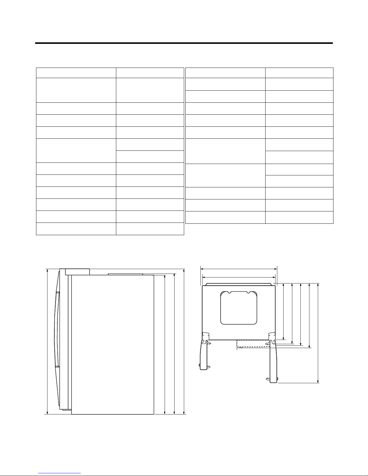
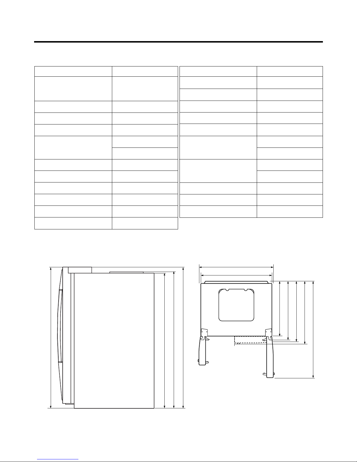
SPECIFICATIONS................................................................................................................................................................... 4
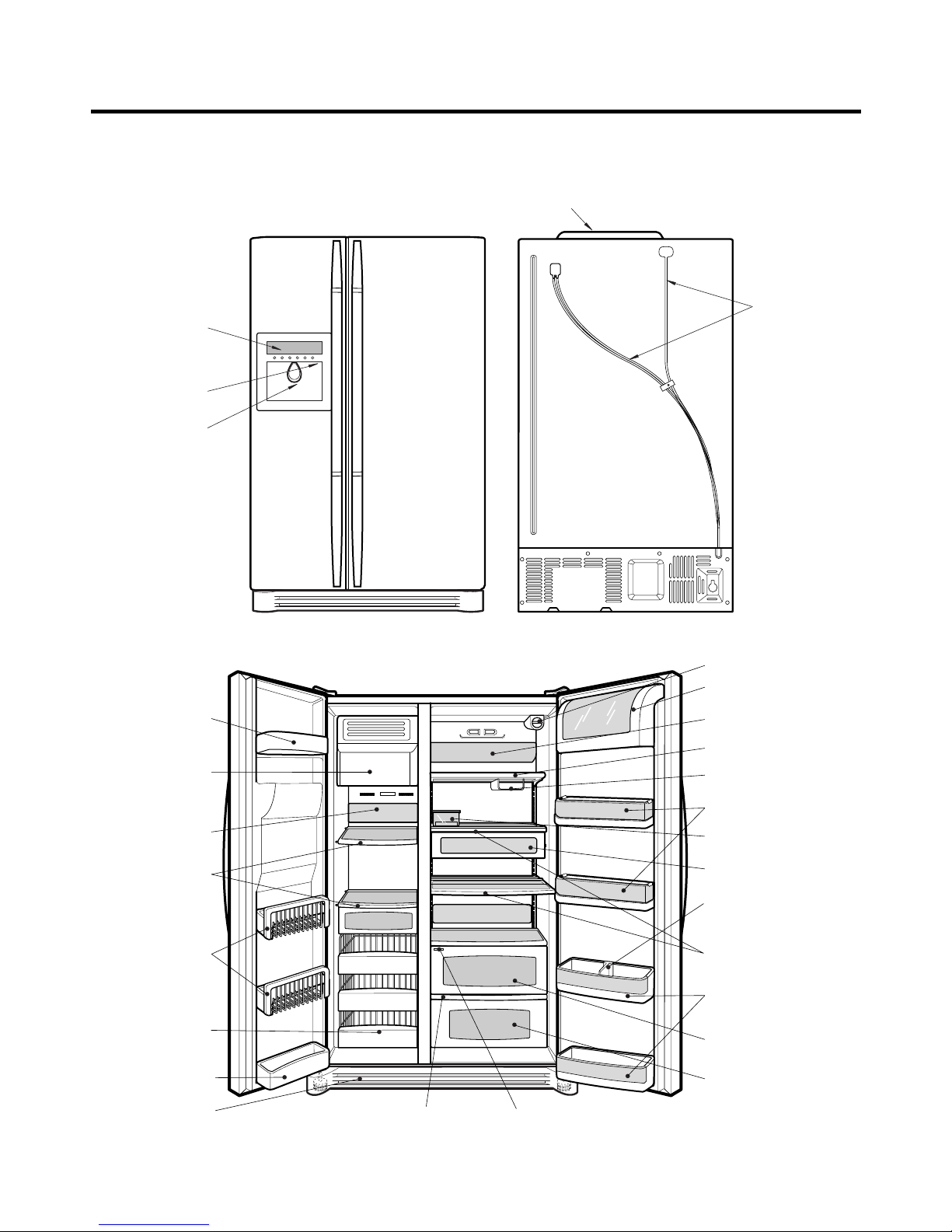
PARTS IDENTIFICATION ....................................................................................................................................................... 9
HOW TO INSTALL THE REFRIGERATOR .......................................................................................................................... 14
HOW TO ADJUST DOOR HEIGHT.................................................................................................................................... 14
FILTER ............................................................................................................................................................................... 15
HOW TO CONTROL THE ICEMAKER WATER SUPPLY.................................................................................................. 16
MICOM FUNCTION .............................................................................................................................................................. 18
EXPLANATION OF MICOM CIRCUIT .................................................................................................................................. 32
EXPLANATION OF PWB CIRCUIT .....................................................................................................................................32
PWB PARTS DIAGRAM AND LIST.....................................................................................................................................47
PWB CIRCUIT DIAGRAM ...................................................................................................................................................54
OPERATION PRINCIPLE AND REPAIR METHOD OF ICEMAKER ................................................................................... 56
OPERATION PRINCIPLE................................................................................................................................................... 56
CONTROL METHOD ACCORDING TO FUNCTIONS....................................................................................................... 57
DEFECT DIAGNOSIS FUNCTION..................................................................................................................................... 59
CIRCUIT................................................................................................................................................................................ 60
TROUBLE DIAGNOSIS........................................................................................................................................................ 63
TROUBLESHOOTING ....................................................................................................................................................... 63
FAULTS .............................................................................................................................................................................. 73
COOLING CYCLE HEAVY REPAIR ................................................................................................................................... 90
HOW TO DEAL WITH CLAIMS.......................................................................................................................................... 97
HOW TO DISASSEMBLE AND ASSEMBLE..................................................................................................................... 103
DOOR............................................................................................................................................................................... 103
HANDLE ........................................................................................................................................................................... 104
FAN SHROUD GRILLE .................................................................................................................................................... 105
ICEMAKER ASSEMBLY................................................................................................................................................... 105
DISPENSER..................................................................................................................................................................... 106
TV-RADIO ............................................................................................................................................................................107
EXPLODED VIEW............................................................................................................................................................... 113
REPLACEMENT PARTS LIST ........................................................................................................................................... 131
CONTENTS
- 2 -

Please observe the following safety precautions to use the
refrigerator safely and correctly and to prevent accident or
injury when servicing.
1. Be careful of an electric shock. Disconnect power cord
from wall outlet and wait for more than three minutes
before replacing PWB parts. Disconnect the power
whenever replacing and repairing electric components.
2. If disconnecting the power, wait at least 5 minutes
before plugging the unit back in.
3. Before touching the power cord, make sure the cord is
not damaged. If the power cord is damaged, it can
cause a fire or an electrical shock.
4. Make sure the unit has a dedicated circuit breaker.
Overloading the circuit can cause a fire.
5. Please make sure the outlet is properly grounded.
Particularly in a wet or damp area.
6. Use standard electrical components.
7. Remove dust and foreign materials from the housing
and connecting parts.
8. Do not fray, damage, run over, kink, bend, pull out, or
twist the power cord.
9. Please check for evidence of moisture intrusion in the
electrical components. Replace the parts or mask with
insulation tape if moisture intrusion is confirmed.
10. Stay clear of the icemaker with hands or tools if the unit
has power. Do not try to manually turn the ice maker
even when turned off.
11. Customers should not repair the refrigerator
themselves. This work requires special tools and
knowledge. Non-professionals could cause fire, injury,
or damage to the product.
12. Do not store flammable materials such as ether,
benzene, alcohol, chemicals, or gas in the refrigerator.
13. Do not put anything on top of the refrigerator,
especially something containing water, like a vase.
14. Do not put glass bottles of water into the freezer. The
contents will freeze and break the bottles.
15. If you scrap or discard the refrigerator, remove the
doors and dispose of it where children are not likely to
play in or around it.
WARNINGS AND PRECAUTIONS FOR SAFETY
- 3 -

SPECIFICATIONS
- 4 -
ITEMS SPECIFICATIONS
DIMENSIONS 908
X
896
X
1771 mm
W
X
D
X
H (3511/16
X
355/16
X
6911/16 in.)
NET WEIGHT 149 kg (328.5 lbs.)
COOLING SYSTEM Fan Cooling
TEMPERATURE CONTROL Micom Control
DEFROSTING SYSTEM Full Automatic
Heater Defrost
INSULATION Cyclo-Pentane
COMPRESSOR PTC Starting Type
EVAPORATOR Fin Tube Type
CONDENSER Wire Condenser
REFRIGERANT R134a (185g) (61/2oz.)
LUBRICATING OIL FREOL @10G (320 cc)
ITEMS SPECIFICATIONS
DRIER MOLECULAR SIEVE XH-7
CAPILLARY TUBE ID Ø0.83
FIRST DEFROST 4 - 5 Hours
DEFROST CYCLE 13 - 15 Hours
DEFROSTING DEVICE Heater, Sheath
ANTI-SWEAT HEATER Dispenser Duct Door Heater
Dispenser Heater
ANTI-FREEZING HEATER Water Tank Heater
Damper Heater
FREEZER LAMP 40W (2 EA)
REFRIGERATOR LAMP 40W (4 EA)
DISPENSER LAMP 15W (1 EA)
724 mm (281/2in.)
1004 mm (391/2in.)
908 mm (353/4in.)
779 mm (305/8in.)
829 mm (325/8in.)
897 mm (355/16 in.)
1261 mm (495/8in.)
1741.5 mm (681/2in.)
1746.5 mm (683/4in.)
1771 mm (6911/16 in.)
Front View Top View
Ref No. : LRSC26944**

SPECIFICATIONS
- 5 -
724 mm (281/2in.)
1004 mm (391/2in.)
908 mm (353/4in.)
779 mm (305/8in.)
829 mm (325/8in.)
897 mm (355/16 in.)
1261 mm (495/8in.)
1741.5 mm (681/2in.)
1746.5 mm (683/4in.)
1771 mm (6911/16 in.)
Ref No. : LRSC26930**
ITEMS SPECIFICATIONS
DIMENSIONS 908
X
896
X
1771 mm
W
X
D
X
H (3511/16
X
355/16
X
6911/16 in.)
NET WEIGHT 149 kg (328.5 lbs.)
COOLING SYSTEM Fan Cooling
TEMPERATURE CONTROL Micom Control
DEFROSTING SYSTEM Full Automatic
Heater Defrost
INSULATION Cyclo-Pentane
COMPRESSOR PTC Starting Type
EVAPORATOR Fin Tube Type
CONDENSER Wire Condenser
REFRIGERANT R134a (185g) (61/2oz.)
LUBRICATING OIL FREOL @10G (320 cc)
ITEMS SPECIFICATIONS
DRIER MOLECULAR SIEVE XH-7
CAPILLARY TUBE ID Ø0.83
FIRST DEFROST 4 - 5 Hours
DEFROST CYCLE 13 - 15 Hours
DEFROSTING DEVICE Heater, Sheath
ANTI-SWEAT HEATER Dispenser Duct Door Heater
Dispenser Heater
ANTI-FREEZING HEATER Water Tank Heater
Damper Heater
FREEZER LAMP 40W (1 EA)
REFRIGERATOR LAMP 40W (4 EA)
DISPENSER LAMP 15W (1 EA)
Front View Top View

SPECIFICATIONS
- 6 -
ITEMS SPECIFICATIONS
DIMENSIONS 908
X
896
X
1771 mm
W
X
D
X
H (3511/16
X
355/16
X
6911/16 in.)
NET WEIGHT 149 kg (328.5 lbs.)
COOLING SYSTEM Fan Cooling
TEMPERATURE CONTROL Micom Control
DEFROSTING SYSTEM Full Automatic
Heater Defrost
INSULATION Cyclo-Pentane
COMPRESSOR PTC Starting Type
EVAPORATOR Fin Tube Type
CONDENSER Wire Condenser
REFRIGERANT R134a (185g) (61/2oz.)
LUBRICATING OIL FREOL @10G (320 cc)
ITEMS SPECIFICATIONS
DRIER MOLECULAR SIEVE XH-7
CAPILLARY TUBE ID Ø0.83
FIRST DEFROST 4 - 5 Hours
DEFROST CYCLE 13 - 15 Hours
DEFROSTING DEVICE Heater, Sheath
ANTI-SWEAT HEATER Dispenser Duct Door Heater
Dispenser Heater
ANTI-FREEZING HEATER Water Tank Heater
Damper Heater
FREEZER LAMP 40W (1 EA)
REFRIGERATOR LAMP 40W (4 EA)
DISPENSER LAMP 15W (1 EA)
724 mm (281/2in.)
1004 mm (391/2in.)
908 mm (353/4in.)
779 mm (305/8in.)
829 mm (325/8in.)
897 mm (355/16 in.)
1261 mm (495/8in.)
1741.5 mm (681/2in.)
1746.5 mm (683/4in.)
1771 mm (6911/16 in.)
Ref No. : LRSC26920**, LRSC26922**
Front View Top View

SPECIFICATIONS
- 7 -
ITEMS SPECIFICATIONS
DIMENSIONS 908
X
896
X
1771 mm
W
X
D
X
H (3511/16
X
355/16
X
6911/16 in.)
NET WEIGHT 149 kg (328.5 lbs.)
COOLING SYSTEM Fan Cooling
TEMPERATURE CONTROL Micom Control
DEFROSTING SYSTEM Full Automatic
Heater Defrost
INSULATION Cyclo-Pentane
COMPRESSOR PTC Starting Type
EVAPORATOR Fin Tube Type
CONDENSER Wire Condenser
REFRIGERANT R134a (185g) (61/2oz.)
LUBRICATING OIL FREOL @10G (320 cc)
ITEMS SPECIFICATIONS
DRIER MOLECULAR SIEVE XH-7
CAPILLARY TUBE ID Ø0.83
FIRST DEFROST 4 - 5 Hours
DEFROST CYCLE 13 - 15 Hours
DEFROSTING DEVICE Heater, Sheath
ANTI-SWEAT HEATER Dispenser Duct Door Heater
Dispenser Heater
ANTI-FREEZING HEATER Water Tank Heater
Damper Heater
FREEZER LAMP 40W (1 EA)
REFRIGERATOR LAMP 40W (3 EA)
DISPENSER LAMP 15W (1 EA)
724 mm (281/2in.)
1004 mm (391/2in.)
908 mm (353/4in.)
779 mm (305/8in.)
829 mm (325/8in.)
892 mm (351/8in.)
1261 mm (495/8in.)
1741.5 mm (681/2in.)
1746.5 mm (683/4in.)
1771 mm (6911/16 in.)
Front View Top View
Ref No. : LRSC26910**, LRSC26911**

SPECIFICATIONS
- 8 -
ITEMS SPECIFICATIONS
DIMENSIONS 908
X
896
X
1771 mm
W
X
D
X
H (3511/16
X
355/16
X
6911/16 in.)
NET WEIGHT 154 kg (339.5 lbs.)
COOLING SYSTEM Fan Cooling
TEMPERATURE CONTROL Micom Control
DEFROSTING SYSTEM Full Automatic
Heater Defrost
INSULATION Cyclo-Pentane
COMPRESSOR PTC Starting Type
EVAPORATOR Fin Tube Type
CONDENSER Wire Condenser
REFRIGERANT R134a (185g) (61/2oz.)
LUBRICATING OIL FREOL @10G (320 cc)
ITEMS SPECIFICATIONS
DRIER MOLECULAR SIEVE XH-7
CAPILLARY TUBE ID Ø0.83
FIRST DEFROST 4 - 5 Hours
DEFROST CYCLE 13 - 15 Hours
DEFROSTING DEVICE Heater, Sheath
ANTI-SWEAT HEATER Dispenser Duct Door Heater
Dispenser Heater
ANTI-FREEZING HEATER Water Tank Heater
Damper Heater
FREEZER LAMP 40W (2 EA)
REFRIGERATOR LAMP 40W (4 EA)
DISPENSER LAMP 15W (1 EA)
724 mm (281/2in.)
1004 mm (391/2in.)
908 mm (353/4in.)
779 mm (305/8in.)
829 mm (325/8in.)
897 mm (355/16 in.)
1261 mm (495/8in.)
1741.5 mm (681/2in.)
1746.5 mm (683/4in.)
1771 mm (6911/16 in.)
Front View Top View
Ref No. : LRSC26980TT

PARTS IDENTIFICATION
- 9 -
Humidity SwitchOptiChill Display
Lamp
Shelf
Egg Box
Snack Drawer
Vegetable Drawer
OptiChill
Door Rack
Shelf
Grab and Go
Can Server
Lamp
Lower Cover
Dairy Products Corner
Water Filter
Door Rack
Drawer
(Wire/Plastic)
Freezer
Compartment
Refrigerator
Compartment
Automatic
Icemaker
Door Rack
Shelf
Door Rack
Bottle Guide
Display Panel
Dispenser Lamp
Ice & Water
Dispenser Button
PCB Cover
Water Tubes
Ref No. : LRSC26944**

Ref No. : LRSC26930**
PARTS IDENTIFICATION
- 10 -
Humidity Switch
Lamp
Shelf
Egg Box
Snack Drawer
Vegetable Drawer
OptiChill
Door Rack
Shelf
Grab and Go
Wine Holder
Lamp
Lower Cover
Dairy Products Corner
Door Rack
Drawer
(Wire/Plastic)
Freezer
Compartment
Refrigerator
Compartment
Automatic
Icemaker
Door Rack
Shelf
Bottle Guide
Display Panel
Dispenser Lamp
Ice & Water
Dispenser Button
OptiChill Display
Door Rack
Water Filter
PCB Cover
Water Tubes

PARTS IDENTIFICATION
- 11 -
Humidity Switch
Lamp
Shelf
Egg Box
Snack Drawer
Vegetable Drawer
Vegetable Drawer
/Meat Drawer
Door Rack
Shelf
Door Rack
Wine Holder
Lamp
Lower Cover
Dairy Products Corner
Door Rack
Drawer
(Wire/Plastic)
Freezer
Compartment
Refrigerator
Compartment
Automatic
Icemaker
Door Rack
Shelf
Bottle Guide
Display Panel
Dispenser Lamp
Ice & Water
Dispenser Button
PCB Cover
Water Tubes
Door Rack
Water Filter
Ref No. : LRSC26920**, LRSC26922**

Ref No. : LRSC26910**, LRSC26911**
PARTS IDENTIFICATION
- 12 -
Lamp
Shelf
Egg Box
Snack Drawer
Vegetable Drawer
Vegetable Drawer
/Meat Drawer
Door Rack
Shelf
Door Rack
Wine Holder
Lamp
Lower Cover
Dairy Products Corner
Door Rack
Drawer
(Wire/Plastic)
Freezer
Compartment
Refrigerator
Compartment
Automatic
Icemaker
Door Rack
Shelf
PCB Cover
Water Tubes
Door Rack
Water Filter
Humidity Switch
Bottle Guide
Display Panel
Dispenser Lamp
Ice & Water
Dispenser Button

PARTS IDENTIFICATION
- 13 -
Humidity SwitchOptiChill Display
Lamp
Shelf
Egg Box
Snack Drawer
Vegetable Drawer
OptiChill
Door Rack
Shelf
Grab and Go
Can Server
Lamp
Lower Cover
Dairy Products Corner
Water Filter
Door Rack
Drawer
(Wire/Plastic)
Freezer
Compartment
Refrigerator
Compartment
Automatic
Icemaker
Door Rack
Shelf
Door Rack Bottle Guide
Display Panel
Dispenser Lamp
Ice & Water
Dispenser Button
PCB Cover
Water Tubes
Ref No. : LRSC26980TT

How to Adjust Door Height of Refrigerator
■Level the refrigerator first. (If the refrigerator is not installed on a flat floor, the height of freezer and refrigerator doors
may not be the same.)
If the freezer door is lower than the refrigerator door: If the freezer door is higher than the refrigerator door:
Insert a driver into the groove of the adjusting
screw and turn in the direction of the arrow (clockwise)
until the refrigerator is level.
Insert a driver into the groove of the adjusting
screw and turn in the direction of the arrow (clockwise)
until the refrigerator is level.
HOW TO INSTALL REFRIGERATOR
- 14 -
Adjusting
Screw
Driver
Height
Difference
Height
Difference
Height
Difference
Height
Difference
1
2

Filter
Replace the filter when the indicator light comes on or the
performance of the icemaker or water dispenser decreases
noticeably.
After changing the water filter cartridge, reset the water
filter status display and indicator light by pressing and
holding the BUTTON for 3 seconds.(page 18)
1. Remove the old cartridge.
Twist the knob of the cartridge counter clockwise.
When the cartridge is removed, you will feel it click .
Pull out the cartridge.
NOTE: There will be some water(25cc) in the filter
cartridge. Some spilling may occur. Catch it in a
bowl or towel.
2. Replace with a new cartridge.
Take the new cartridge out of its packaging and remove the
protective cover from the o-rings.
With the cartridge knob in the vertical position, push the
new filter cartridge into the cover until it stops.
If you can’t turn the filter from side to side, it isn’t fully
inserted. Push it in firmly and twist it into place. You will
hear the snap when it clicks into place.
Using the handle, twist the cartridge clockwise about 1/4
turn.
3. After replacing filter, dispense water through the water
dispenser for 3 minutes to purge the system.
There may be a little air in the line, causing noise or
hissing. Run the water at the dispenser until the hissing
stops.
NOTE: - To purchase replacement water filter cartridges,
visit your local appliance dealer or part distributor,
or call 1-877-714-7486.
- You can also visit our website :
www.lgappliances.com
HOW TO INSTALL REFRIGERATOR
- 15 -

Ice Maker
1) How to Control the Amount of Water Supplied to Icemaker.
Caution : •Do not put hands or tools into the chute to confirm the operation of geared motor.
It may damage the refrigerator or hurt your hands.
To gain access to the ice maker, remove the ice bin in the upper part of the freezer compartment. Then use the water
control switch to change the amount of water supplied to the ice maker.
Water supply amount TABLE
HOW TO INSTALL REFRIGERATOR
- 16 -
21
STAGE TIME TO SUPPLY INDICATIONS REMARKS
1
2
3
4
5
4 sec.
4.5 sec.
5 sec.
5.5 sec.
6 sec.
The water amount will vary depending
on the Water Control Switch setting as
well as the water pressure of the
connected water line.

wwWARNING
Personal Injury Hazard
Avoid contact with the moving parts of the ejector
mechanism or with the heating element that releases
the cubes. DO NOT place fingers or hands on the
automatic icemaking mechanism while the refrigerator
is plugged in.
2) Operating instructions
A newly-installed refrigerator may take up to 24 hours
to begin making ice.
The icemaker will produce eight cubes per
cycle—approximately 120–150 cubes in a 24-hour period,
depending on freezer compartment temperature, room
temperature, number of door openings and other operating
conditions.
If the refrigerator is used before the water connection is
made to the icemaker, set the power switch to O (off).
When the refrigerator has been connected to the water
supply, set the power switch to I (on).
The icemaker will fill with water when it cools to freezing. A
newly-installed refrigerator may take up to 24 hours to
begin making ice cubes.
Throw away the first few batches of ice to allow the water
line to clear.
Be sure nothing interferes with the sweep of the feeler arm.
When the bin fills to the level of the feeler arm, the
icemaker will stop producing ice.
It is normal for several cubes to be stuck together.
If ice is not used frequently, old ice cubes will become
cloudy, taste stale, and shrink.
NOTE: If the cube size is smaller or larger than you
expected, you can regulate the size with the cube size
button. (normally caused by variations in water pressure.)
Every time you press the cube size button, the indicator
light goes up. The higher the position indicated, the larger
the cubes will be. (1st step is the next after the 5th step.)
3) When you should set the icemaker power
switch to O (off)
•When the water supply will be shut off for several hours.
•When the ice storage bin is removed for more than a
minute or two.
•When the refrigerator will not be used for several days.
4) Normal sounds you may hear
•The icemaker water valve will buzz as the icemaker fills
with water. If the power switch is in the I (on) position, it
will buzz even if it has not yet been hooked up to water.
To stop the buzzing, move the power switch to O (off).
NOTE: Keeping the power switch in the I (on) position
before the water line is connected can damage the
icemaker.
•You will hear the sound of cubes dropping into the bin
and water running in the pipes as the icemaker refills.
5) Preparing for Vacation
Set the icemaker power switch to O (off) and shut off the
water supply to the refrigerator.
If the ambient temperature will drop below freezing, have a
qualified servicer drain the water supply system (on some
models) to prevent serious property damage due to
flooding from ruptured water lines or connections.
HOW TO INSTALL REFRIGERATOR
- 17 -
Feeler Arm
Icemaker
Cube Size
Indicator Light Water Supply
Control Switch
Power Switch

1. Monitor Panel
1-1. LRSC26944**, LRSC26980TT
1-2. LRSC26930**
1-3. LRSC26910**, LRSC26911**, LRSC26920**, LRSC26922**
MICOM FUNCTION
- 18 -
ICEBEAM
COOLING
OFF
CUBE FILTER
MONTH
EXPRESS/JET FRZ DISPENSER FREEZER REFRIGERATOR FILTER/LIGHT LOOK
ROOM TEMP
DISPENSER & KEY
F
WATER 5
4
3
2
1
CRUSH
F F
3 SECS
Dispenser selection
button
Express Freezer/Jet Freezer
function selection button Dispenser and Button
Lock button
Filter Timer Reset & Dispenser
Light Toggle
Refrigerator Compartment
Temperature Setting
Freezer Compartment
Temperature Setting
EXPRESS
DIGITAL CONTROL
FRZ TEMP REF TEMP
JET
CUBE
FILTER RESET
HOLD 3SECS
EXPRESS/JET FRZ DISPENSER FREEZER
REFRIGERATOR
FILTER RESET/LIGHT
LOOK
ROOM TEMP
LOCK
DISPENSER & KEY
WATER
CRUSH
3 SECS
F
C
F
C
F
C
FILTER
ON
DIGITAL CONTROL
FRZ TEMP REF TEMP
OFF
CUBE
FILTER RESET
HOLD 3SECS
EXPRESS FRZ DISPENSER FREEZER
REFRIGERATOR
FILTER RESET/LIGHT
LOOK
ROOM TEMP
LOCK
DISPENSER & KEY
WATER
CRUSH
3 SECS
F
C
F
C
F
C
FILTER

2. Refrigerator Functions
2-1-1. Temperature Selection (LRSC26944**, LRSC26980TT)
* The temperature can vary ±3 °C depending on the load condition.
❉Whenever pressing the button, setting is repeated in the order of (Medium) ➝(Medium Cold) ➝(Coldest) ➝(Warmest) ➝
(Medium Warm).
• The actual inner temperature varies depending on the food status, as the indicated setting temperature is a target
temperature, not the actual temperature within the refrigerator.
• A newly installed refrigerator will take 24 hours minimum for temperatures to stabilize. The temperature should be
checked and adjusted as necessary after 2 or 3 days.
2-1-2. LCD Back Light Control (LRSC26944**, LRSC26980TT)
1. In order to see the LCD display more easily, the backlight is turned on for one minute at the initial application of power, for
20 seconds when buttons are pressed, when a door is opened, and for 20 seconds after the door is closed.
2. When any display button is pressed while the backlight is off, the bell sounds and the backlight is turned on, but the
button function is not performed. In other words, pressing any button turns on the backlight but does not cause any
function to be initiated.
3. To check the LCD graphic and back light ON/OFF status, press and hold the EXPRESS/JET FRZ and FREEZER buttons.
This will turn the back light on and illuminate all of the graphics. When the buttons are released, the graphic display
returns to its previous setting and the back light is turned off.
2-1-3. Room temperature display function
1. The sensor for the ROOM TEMP display is located under the upper right hinge cover. Factors such as air flow, lighting,
and other appliances operating within the room, may cause the display to differ from other temperature displays in the
same room.
2. Ambient temperature is displayed between 16°F and 120°F. Temperatures 15°F and below are displayed as Lo and
temperatures 121°F and above are displayed as Hi. If the ambient temperature sensor fails, Er will be displayed.
MICOM FUNCTION
- 19 -
Division Power Initially On 1st Press 2st Press 3th Press 4th Press
Setting
temperature
Temperature
Control Medium Medium Cold Coldest Warmest Medium Warm
Freezer Control
-2 °F -5 °F -8 °F 7 °F 4 °F
Refrigeration 37 °F 34 °F 32 °F 46 °F 41 °F
Control
5
4
3
2
1
5
4
3
2
1
5
4
3
2
1
5
4
3
2
1
5
4
3
2
1

2-1-4. Lock function (dispenser and display button lock)
1. When the refrigerator is first powered up, the Lock function is turned off.
2. To lock the display, the dispenser, and the control panel, press and hold the LOCK button for more than 3 seconds. The
LOCK text on the display will be turned on.
3. To unlock the controls, press and hold the lock button for more than 3 seconds. The LOCK text on the display will be
turned off.
2-1-5. Filter condition display function
LCD (LRSC26944**, LRSC26980TT)
1. This units displays the months left before the water filter needs to be changed. It starts when the unit is first plugged in.
2. After 6 months have passed the filter change will appear on the display. It will show FILTER LIGHT 3 SECS.
3. Press and hold the filter button for 3 seconds to reset the filter timer.
LED (All models except LRSC26944**, LRSC26980TT)
1. There is a replacement indicator light for the water filter cartridge on the dispenser.
2. The water filter should be replaced every six months or about 28,000 seconds' filtering time.
3. The water filter light and FILTER RESET HOLD 3 SECS will show in the display to remind you to change the filter soon.
4. After replacing the filter, press and hold the lock button for more than 3 seconds. The FILTER RESET HOLD 3 SECS will
turn off.
MICOM FUNCTION
- 20 -
DISPENSER & KEY
3 SECS
LOCK
DISPENSER & KEY
3 SECS
LOCK CONTROL
DISPENSER & KEY
3 SECS
LOCK
DISPENSER & KEY
3 SECS
LOCK CONTROL
Ex) Select
LOCK
Ex) Select
LOCK again
Ex) Select
LOCK
Ex) Select
LOCK again
In initial
Power On
Classification
Filter Status
Display
Pass of
a month
Pass of
2 months
Pass of
3 months
Pass of
4 months
Pass of
5 months
Pass of
6 months
3 SECS
FILTER
MONTH
FILTER
MONTH
FILTER
MONTH
FILTER
MONTH
FILTER
MONTH
FILTER
MONTH
FILTER
MONTH
FILTER LIGHT
In initial Power On
/ Filter RESET
Replace indicator
light on
Classification
Filter Status
Display
FILTER
FILTER RESET
HOLD 3SECS
FILTER
LCD (LRSC26944**, LRSC26980TT) LED (All models except LRSC26944**, LRSC26980TT)
3 SECS
FILTER LIGHT
Other manuals for LRSC26980TT
1
This manual suits for next models
12
Table of contents
Other LG Refrigerator manuals

LG
LG GSL325PVCVD User manual

LG
LG GC-L227FNSL User manual

LG
LG LMXS3006 Series User manual

LG
LG LSXS26336V User manual

LG
LG GLT51SWGSZ User manual

LG
LG LRMVS2806 Series User manual

LG
LG LRBC22544SB User manual

LG
LG LFX28978 Series User manual

LG
LG G-B592GGC Series User manual

LG
LG Kimchi GR-K24PS User manual

LG
LG Fridge-Freezer User manual

LG
LG GM5148AERV User manual

LG
LG GV-B258R4 Series User manual

LG
LG LFX28978 Series User manual

LG
LG LFXS24623S/01 User manual

LG
LG LRFCS2503 Series User manual

LG
LG REFRIGERATOR User manual

LG
LG LRMVS2806D User manual

LG
LG LRBC20512WW - 19.7 Cu. Ft. Bottom-Freezer... User manual

LG
LG LSC23924ST User manual