LG GR-B197GVQ User manual

CAUTION
PLEASE
READ
CAREFULLY
THE
SAFETY
PRECAUTIONS
OF
THIS
BOOK
BEFORE
CHECKING
OR
OPERATING
THE
REFRIGERATOR.
REFRIGERATOR
SERVICE
MANUAL
MODEL:
GR-B197GT
Q
COLOR:
TITANIUM
http://biz.lgservice.com
Ref.No.
GR-B197GTQ
GR-B197GVQ
GR-B197GVQ
SUPER
WHITE

WARNINGS
AND
PRECAUTIONS
FOR
SAFETY
................................................................................................................
3
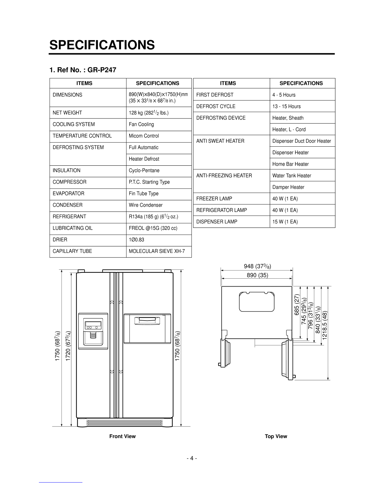
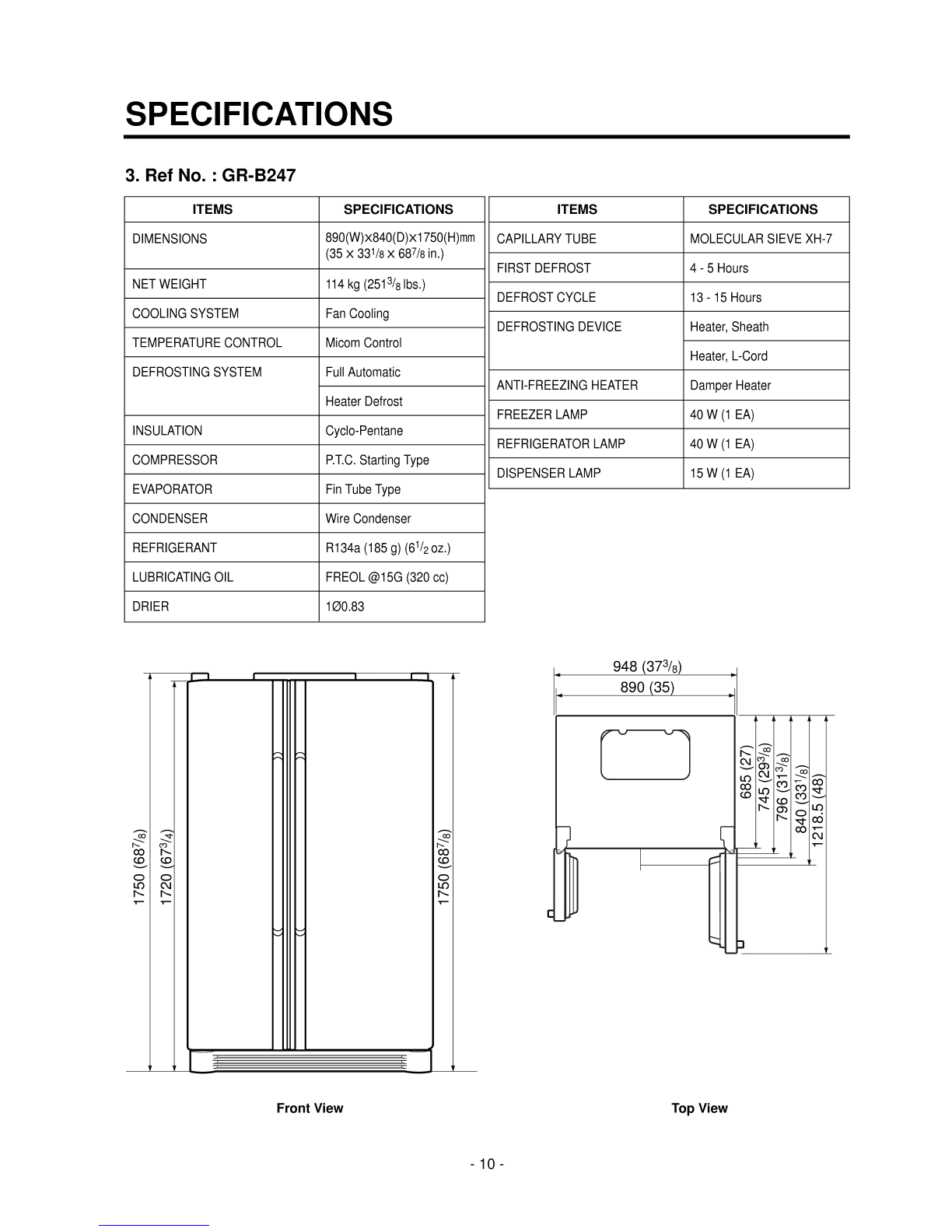
SPECIFICATIONS...................................................................................................................................................................
4
PARTS
IDENTIFICATION
.....................................................................................................................................................
12
HOW
TO
INSTALL
THE
REFRIGERATOR
..........................................................................................................................
18
HOW
TO
ADJUST
DOOR
HEIGHT
OF
THE
REFRIGERATOR
........................................................................................
18
HOW
TO
CONTROL
THE
AMOUNT
OF
WATER
SUPPLIED
TO
THE
ICEMAKER
.........................................................
20
MICOM
FUNCTION
..............................................................................................................................................................
22
EXPLANATION
FOR
MICOM
CIRCUIT
...............................................................................................................................
28
EXPLANATION
FOR
PWB
CIRCUIT
.................................................................................................................................
28
COMPENSATION
CIRCUIT
FOR
TOO
WARM,
TOO
COLD
AT
FREEZER......................................................................
43
PWB
PARTS
DRAWING
AND
LIST
...................................................................................................................................
44
PWB
CIRCUIT
DIAGRAM
..................................................................................................................................................
54
ICEMAKER
AND
DISPENSER
OPERATION
PRINCIPLE
AND
REPAIR
METHOD...........................................................
58
WORKING
PRINCIPLES....................................................................................................................................................
58
FUNCTION
OF
ICEMAKER
...............................................................................................................................................
59
ICEMAKER
TROUBLESHOOTING....................................................................................................................................
62
ICEMAKER
CIRCUIT
PART
...............................................................................................................................................
63
CIRCUIT
................................................................................................................................................................................
64
TROUBLE
DIAGNOSIS
........................................................................................................................................................
66
TROUBLESHOOTING
.......................................................................................................................................................
66
FAULTS
..............................................................................................................................................................................
76
COOLING
CYCLE
HEAVY
REPAIR
...................................................................................................................................
93
HOW
TO
DEAL
WITH
CLAIMS
........................................................................................................................................
100
HOW
TO
DISASSEMBLE
AND
ASSEMBLE
.....................................................................................................................
105
DOOR
...............................................................................................................................................................................
105
HANDLE
...........................................................................................................................................................................
106
SHROUD,
GRILLE
FAN
...................................................................................................................................................
106
ICEMAKER
.......................................................................................................................................................................
106
DISPENSER
.....................................................................................................................................................................
107
WATER
TANK
AND
WATER
LINE....................................................................................................................................
109
HOME
BAR
......................................................................................................................................................................
109
EXPLODED
VIEW...............................................................................................................................................................
110
REPLACEMENT
PARTS
LIST............................................................................................................................................
119
CONTENTS
-2-

Please
observe
the
following
safety
precautions
to
use
the
refrigerator
safely
and
correctly
and
to
prevent
accident
or
injury
when
servicing.
1.
Be
careful
of
an
electric
shock.
Disconnect
power
cord
from
wall
outlet
and
wait
for
more
than
three
minutes
before
replacing
PWB
parts.
Shut
off
the
power
whenever
replacing
and
repairing
electric
components.
2.
When
connecting
power
cord,
please
wait
for
more
than
five
minutes
after
power
cord
was
disconnected
from
the
wall
outlet.
3.
Please
check
if
the
power
plug
is
pressed
down
by
the
refrigerator
against
the
wall.
If
the
power
plug
was
damaged,
it
may
cause
fire
or
electric
shock.
4.
If
the
wall
outlet
is
overloaded,
it
may
cause
fire.
Please
use
a
dedicated
circuit
for
the
refrigerator.
5.
Please
make
sure
the
outlet
is
properly
grounded,
particularly
in
a
wet
or
damp
area.
6.
Use
standard
electrical
components.
7.
Make
sure
hooks
are
correctly
engaged.
Remove
dust
and
foreign
materials
from
the
housing
and
connecting
parts.
8.
Do
not
fray,
damage,
machine,
heavily
bend,
pull
out,
or
twist
the
power
cord.
9.
Please
check
for
evidence
of
moisture
intrusion
in
the
electrical
components.
Replace
the
parts
or
mask
with
insulation
tape
if
moisture
intrusion
was
confirmed.
10.
Do
not
touch
the
icemaker
with
hands
or
tools
to
confirm
the
operation
of
geared
motor.
11.
Do
not
suggest
that
customers
repair
their
refrigerator
themselves.
This
work
requires
special
tools
and
knowledge.
Non-professionals
could
cause
fire,
injury,
or
damage
to
the
product.
12.
Do
not
store
flammable
materials
such
as
ether,
benzene,
alcohol,
chemicals,
gas,
or
medicine
in
the
refrigerator.
13.
Do
not
put
anything
on
top
of
the
refrigerator,
especially
something
containing
water,
like
a
vase.
14.
Do
not
put
glass
bottles
with
full
of
water
into
the
freezer.
The
contents
will
freeze
and
break
the
glass
bottles.
15.
When
you
scrap
or
discard
the
refrigerator,
please
remove
the
doors
and
dispose
of
it
where
children
are
not
likely
to
play
in
or
around
it.
WARNINGS
AND
PRECAUTIONS
FOR
SAFETY
-3-

SPECIFICATIONS
-4-
ITEMS
SPECIFICATIONS
DIMENSIONS
890(W)X840(D)X1750(H)mm
(35X33
1
/8X68
7
/8
in.)
NET
WEIGHT
128
kg
(282
1
/
2
lbs.)
COOLING
SYSTEM
Fan
Cooling
TEMPERATURE
CONTROL
Micom
Control
DEFROSTING
SYSTEM
Full
Automatic
Heater
Defrost
INSULATION
Cyclo-Pentane
COMPRESSOR
P.T.C.
Starting
Type
EVAPORATOR
Fin
Tube
Type
CONDENSER
Wire
Condenser
REFRIGERANT
R134a
(185
g)
(6
1
/
2
oz.)
LUBRICATING
OIL
FREOL
@15G
(320
cc)
DRIER
1Ø0.83
CAPILLARY
TUBE
MOLECULAR
SIEVE
XH-7
ITEMS
SPECIFICATIONS
FIRST
DEFROST
4-5Hours
DEFROST
CYCLE
13
-
15
Hours
DEFROSTING
DEVICE
Heater,
Sheath
Heater,
L
-
Cord
ANTI
SWEAT
HEATER
Dispenser
Duct
Door
Heater
Dispenser
Heater
Home
Bar
Heater
ANTI-FREEZING
HEATER
Water
Tank
Heater
Damper
Heater
FREEZER
LAMP
40W(1EA)
REFRIGERATOR
LAMP
40W(1EA)
DISPENSER
LAMP
15W(1EA)
1750 (68
7
/
8
)
1720 (67
3
/
4
)
1750 (68
7
/
8
)
685 (27)
948
(37
3
/
8
)
890
(35)
745 (29
3
/
8
)
796 (31
3
/
8
)
840 (33
1
/
8
)
1218.5 (48)
1.
Ref
No.
:
GR-P247
Front
View
Top
View

SPECIFICATIONS
-5-
1750 (68
7
/
8
)
1720 (67
3
/
4
)
1750 (68
7
/
8
)
600 (23
5
/
8
)
948
(37
3
/
8
)
890
(35)
660 (26)
711 (28)
755 (29
3
/
4
)
1133.5 (44
5
/
8
)
Front
View
Top
View
2.
Ref
No.
:
GR-P207
ITEMS
SPECIFICATIONS
FIRST
DEFROST
4-5Hours
DEFROST
CYCLE
13
-
15
Hours
DEFROSTING
DEVICE
Heater,
Sheath
Heater,
L
-
Cord
ANTI
SWEAT
HEATER
Dispenser
Duct
Door
Heater
Dispenser
Heater
Home
Bar
Heater
ANTI-FREEZING
HEATER
Water
Tank
Heater
Damper
Heater
FREEZER
LAMP
40W(1EA)
REFRIGERATOR
LAMP
40W(1EA)
DISPENSER
LAMP
15W(1EA)
ITEMS
SPECIFICATIONS
DIMENSIONS
890(W)X755(D)X1750(H)mm
(35X29
3
/4X68
7
/8
in.)
NET
WEIGHT
123
kg
(271
1
/
8
lbs.)
COOLING
SYSTEM
Fan
Cooling
TEMPERATURE
CONTROL
Micom
Control
DEFROSTING
SYSTEM
Full
Automatic
Heater
Defrost
INSULATION
Cyclo-Pentane
COMPRESSOR
P.T.C.
Starting
Type
EVAPORATOR
Fin
Tube
Type
CONDENSER
Wire
Condenser
REFRIGERANT
R134a
(185
g)
(6
1
/
2
oz.)
LUBRICATING
OIL
FREOL
@15G
(320
cc)
DRIER
1Ø0.83
CAPILLARY
TUBE
MOLECULAR
SIEVE
XH-7

SPECIFICATIONS
-6-
ITEMS
SPECIFICATIONS
DIMENSIONS
890(W)X840(D)X1750(H)mm
(35X33
1
/8X68
7
/8
in.)
NET
WEIGHT
125
kg
(275
5
/
8
lbs.)
COOLING
SYSTEM
Fan
Cooling
TEMPERATURE
CONTROL
Micom
Control
DEFROSTING
SYSTEM
Full
Automatic
Heater
Defrost
INSULATION
Cyclo-Pentane
COMPRESSOR
P.T.C.
Starting
Type
EVAPORATOR
Fin
Tube
Type
CONDENSER
Wire
Condenser
REFRIGERANT
R134a
(185
g)
(6
1
/
2
oz.)
LUBRICATING
OIL
FREOL
@15G
(320
cc)
DRIER
1Ø0.83
ITEMS
SPECIFICATIONS
CAPILLARY
TUBE
MOLECULAR
SIEVE
XH-7
FIRST
DEFROST
4-5Hours
DEFROST
CYCLE
13
-
15
Hours
DEFROSTING
DEVICE
Heater,
Sheath
Heater,
L-Cord
ANTI
SWEAT
HEATER
Dispenser
Duct
Door
Heater
Dispenser
Heater
ANTI-FREEZING
HEATER
Water
Tank
Heater
Damper
Heater
FREEZER
LAMP
40W(1EA)
REFRIGERATOR
LAMP
40W(1EA)
DISPENSER
LAMP
15W(1EA)
685 (27)
948
(37
3
/
8
)
890
(35)
745 (29
3
/
8
)
796 (31
3
/
8
)
840 (33
1
/
8
)
1218.5 (48)
1750 (68
7
/
8
)
1720 (67
3
/
4
)
1750 (68
7
/
8
)
Front
View
Top
View
3.
Ref
No.
:
GR-L247

SPECIFICATIONS
-7-
ITEMS
SPECIFICATIONS
DIMENSIONS
890(W)X755(D)X1750(H)mm
(35X29
3
/4X68
7
/8
in.)
NET
WEIGHT
120
kg
(264
1
/
2
lbs.)
COOLING
SYSTEM
Fan
Cooling
TEMPERATURE
CONTROL
Micom
Control
DEFROSTING
SYSTEM
Full
Automatic
Heater
Defrost
INSULATION
Cyclo-Pentane
COMPRESSOR
P.T.C.
Starting
Type
EVAPORATOR
Fin
Tube
Type
CONDENSER
Wire
Condenser
REFRIGERANT
R134a
(185
g)
(6
1
/
2
oz.)
LUBRICATING
OIL
FREOL
@15G
(320
cc)
DRIER
1Ø0.83
ITEMS
SPECIFICATIONS
CAPILLARY
TUBE
MOLECULAR
SIEVE
XH-7
FIRST
DEFROST
4-5Hours
DEFROST
CYCLE
13
-
15
Hours
DEFROSTING
DEVICE
Heater,
Sheath
Heater,
L-Cord
ANTI
SWEAT
HEATER
Dispenser
Duct
Door
Heater
Dispenser
Heater
ANTI-FREEZING
HEATER
Water
Tank
Heater
Damper
Heater
FREEZER
LAMP
40W(1EA)
REFRIGERATOR
LAMP
40W(1EA)
DISPENSER
LAMP
15W(1EA)
1750 (68
7
/
8
)
1720 (67
3
/
4
)
1750 (68
7
/
8
)
600 (23
5
/
8
)
948
(37
3
/
8
)
890
(35)
660 (26)
711 (28)
755 (29
3
/
4
)
1133.5 (44
5
/
8
)
Front
View
Top
View
4.
Ref
No.
:
GR-L207

SPECIFICATIONS
-8-
ITEMS
SPECIFICATIONS
DIMENSIONS
890(W)X840(D)X1750(H)mm
(35X33
1
/8X68
7
/8
in.)
NET
WEIGHT
117
kg
(257
7
/
8
lbs.)
COOLING
SYSTEM
Fan
Cooling
TEMPERATURE
CONTROL
Micom
Control
DEFROSTING
SYSTEM
Full
Automatic
Heater
Defrost
INSULATION
Cyclo-Pentane
COMPRESSOR
P.T.C.
Starting
Type
EVAPORATOR
Fin
Tube
Type
CONDENSER
Wire
Condenser
REFRIGERANT
R134a
(185
g)
(6
1
/
2
oz.)
LUBRICATING
OIL
FREOL
@15G
(320
cc)
DRIER
1Ø0.83
CAPILLARY
TUBE
MOLECULAR
SIEVE
XH-7
ITEMS
SPECIFICATIONS
FIRST
DEFROST
4-5Hours
DEFROST
CYCLE
13
-
15
Hours
DEFROSTING
DEVICE
Heater,
Sheath
Heater,
L
-
Cord
ANTI
SWEAT
HEATER
Home
Bar
Heater
ANTI-FREEZING
HEATER
Damper
Heater
FREEZER
LAMP
40W(1EA)
REFRIGERATOR
LAMP
40W(1EA)
DISPENSER
LAMP
15W(1EA)
1750 (68
7
/
8
)
1720 (67
3
/
4
)
1750 (68
7
/
8
)
685 (27)
948
(37
3
/
8
)
890
(35)
745 (29
3
/
8
)
796 (31
3
/
8
)
840 (33
1
/
8
)
1218.5 (48)
Front
View
Top
View
1.
Ref
No.
:
GR-C247

SPECIFICATIONS
-9-
ITEMS
SPECIFICATIONS
DIMENSIONS
890(W)X755(D)X1750(H)mm
(35X29
3
/4X68
7
/8
in.)
NET
WEIGHT
112
kg
(246
7
/
8
lbs.)
COOLING
SYSTEM
Fan
Cooling
TEMPERATURE
CONTROL
Micom
Control
DEFROSTING
SYSTEM
Full
Automatic
Heater
Defrost
INSULATION
Cyclo-Pentane
COMPRESSOR
P.T.C.
Starting
Type
EVAPORATOR
Fin
Tube
Type
CONDENSER
Wire
Condenser
REFRIGERANT
R134a
(185
g)
(6
1
/
2
oz.)
LUBRICATING
OIL
FREOL
@15G
(320
cc)
DRIER
1Ø0.83
CAPILLARY
TUBE
MOLECULAR
SIEVE
XH-7
1750 (68
7
/
8
)
1720 (67
3
/
4
)
1750 (68
7
/
8
)
600 (23
5
/
8
)
948
(37
3
/
8
)
890
(35)
660 (26)
711 (28)
755 (29
3
/
4
)
1133.5 (44
5
/
8
)
Front
View
Top
View
2.
Ref
No.
:
GR-C207
ITEMS
SPECIFICATIONS
FIRST
DEFROST
4-5Hours
DEFROST
CYCLE
13
-
15
Hours
DEFROSTING
DEVICE
Heater,
Sheath
Heater,
L
-
Cord
ANTI
SWEAT
HEATER
Home
Bar
Heater
ANTI-FREEZING
HEATER
Damper
Heater
FREEZER
LAMP
40W(1EA)
REFRIGERATOR
LAMP
40W(1EA)
DISPENSER
LAMP
15W(1EA)

SPECIFICATIONS
-10-
ITEMS
SPECIFICATIONS
DIMENSIONS
890(W)
X840(D)X1750(H)mm
(35X33
1
/8X68
7
/8
in.)
NET
WEIGHT
114
kg
(251
3
/
8
lbs.)
COOLING
SYSTEM
Fan
Cooling
TEMPERATURE
CONTROL
Micom
Control
DEFROSTING
SYSTEM
Full
Automatic
Heater
Defrost
INSULATION
Cyclo-Pentane
COMPRESSOR
P.T.C.
Starting
Type
EVAPORATOR
Fin
Tube
Type
CONDENSER
Wire
Condenser
REFRIGERANT
R134a
(185
g)
(6
1
/
2
oz.)
LUBRICATING
OIL
FREOL
@15G
(320
cc)
DRIER
1Ø0.83
ITEMS
SPECIFICATIONS
CAPILLARY
TUBE
MOLECULAR
SIEVE
XH-7
FIRST
DEFROST
4-5Hours
DEFROST
CYCLE
13
-
15
Hours
DEFROSTING
DEVICE
Heater,
Sheath
Heater,
L-Cord
ANTI-FREEZING
HEATER
Damper
Heater
FREEZER
LAMP
40W(1EA)
REFRIGERATOR
LAMP
40W(1EA)
DISPENSER
LAMP
15W(1EA)
1750 (68
7
/
8
)
1720 (67
3
/
4
)
1750 (68
7
/
8
)
685 (27)
948
(37
3
/
8
)
890
(35)
745 (29
3
/
8
)
796 (31
3
/
8
)
840 (33
1
/
8
)
1218.5 (48)
Front
View
Top
View
3.
Ref
No.
:
GR-B247

SPECIFICATIONS
-11-
ITEMS
SPECIFICATIONS
DIMENSIONS
890(W)
X755(D)X1750(H)mm
(35X29
3
/4X68
7
/8
in.)
NET
WEIGHT
109
kg
(240
1
/
4
lbs.)
COOLING
SYSTEM
Fan
Cooling
TEMPERATURE
CONTROL
Micom
Control
DEFROSTING
SYSTEM
Full
Automatic
Heater
Defrost
INSULATION
Cyclo-Pentane
COMPRESSOR
P.T.C.
Starting
Type
EVAPORATOR
Fin
Tube
Type
CONDENSER
Wire
Condenser
REFRIGERANT
R134a
(185
g)
(6
1
/
2
oz.)
LUBRICATING
OIL
FREOL
@15G
(320
cc)
DRIER
1Ø0.83
ITEMS
SPECIFICATIONS
CAPILLARY
TUBE
MOLECULAR
SIEVE
XH-7
FIRST
DEFROST
4-5Hours
DEFROST
CYCLE
13
-
15
Hours
DEFROSTING
DEVICE
Heater,
Sheath
Heater,
L-Cord
ANTI-FREEZING
HEATER
Damper
Heater
FREEZER
LAMP
40W(1EA)
REFRIGERATOR
LAMP
40W(1EA)
DISPENSER
LAMP
15W(1EA)
1750 (68
7
/
8
)
1720 (67
3
/
4
)
1750 (68
7
/
8
)
600 (23
5
/
8
)
948
(37
3
/
8
)
890
(35)
660 (26)
711 (28)
755 (29
3
/
4
)
1133.5 (44
5
/
8
)
Front
View
Top
View
4.
Ref
No.
:
GR-B207

PARTS
IDENTIFICATION
-12-
Cover
PWB
Water
Tube
Cover
Hinge
Home
Bar
Ice
&
Water
Dispenser
Button
Conversion
Switch
(Meats/Vegetables)
Humidity
Switch
Lamp
Shelf
Egg
Box
Snack
Drawer
Vegetable
Drawer
Vegetable
Drawer/
Meat
Drawer
Door
Rack
Refreshment
Center
(optional)
Shelf
Door
Rack
Wine
Holder
(optional)
Lamp
Drawer
or
Shelf
(optional)
Lower
Cover
Dairy
Product
Corner
Door
Rack
Drawer
Freezer
Compartment
Refrigerator
Compartment
Automatic
Icemaker
Door
Rack
Shelf
(Steel/
Tempered
Glass)
Frame
Display
Dispenser
Lamp
1.
Ref
No.
:
GR-P247ER,
GR-P207ER

2.
Ref
No.
:
GR-P247EQ,
GR-P207EQ
PARTS
IDENTIFICATION
-13-
Cover
PWB
Water
Tube
Conversion
Switch
(Meats/Vegetables)
Humidity
Switch
Freezer
Compartment
Refrigerator
Compartment
Cover
Hinge
Home
Bar
Ice
&
Water
Dispenser
Button
Frame
Display
Dispenser
Lamp
Lamp
Shelf
Egg
Box
Snack
Drawer
Vegetable
Drawer
Vegetable
Drawer/
Meat
Drawer
Door
Rack
Refreshment
Center
(optional)
Shelf
Door
Rack
Wine
Holder
(optional)
Lamp
Drawer
or
Shelf
(optional)
Lower
Cover
Dairy
Product
Corner
Door
Rack
Drawer
Automatic
Icemaker
Door
Rack
Shelf
(Steel/
Tempered
Glass)

PARTS
IDENTIFICATION
-14-
Cover
PWB
Water
Tube
Humidity
Switch
Guide
Bottle
Freezer
Compartment
Refrigerator
Compartment
Conversion
Switch
(Meats/Vegetables)
Cover
Hinge
Ice
&
Water
Dispenser
Button
Frame
Display
Dispenser
Lamp
Lamp
Shelf
Egg
Box
Snack
Drawer
Vegetable
Drawer
Vegetable
Drawer/
Meat
Drawer
Door
Rack
Shelf
Door
Rack
Wine
Holder
(optional)
Lamp
Drawer
or
Shelf
(optional)
Lower
Cover
Dairy
Product
Corner
Door
Rack
Drawer
Automatic
Icemaker
Door
Rack
Shelf
(Steel/
Tempered
Glass)
3.
Ref
No.
:
GR-L247ER,
GR-L207ER

4.
Ref
No.
:
GR-L247EQ,
GR-L207EQ
PARTS
IDENTIFICATION
-15-
Conversion
Switch
(Meats/Vegetables)
Cover
PWB
Water
Tube
Humidity
Switch
Freezer
Compartment
Refrigerator
Compartment
Cover
Hinge
Ice
&
Water
Dispenser
Button
Frame
Display
Dispenser
Lamp
Guide
Bottle
Lamp
Shelf
Egg
Box
Snack
Drawer
Vegetable
Drawer
Vegetable
Drawer/
Meat
Drawer
Door
Rack
Shelf
Door
Rack
Wine
Holder
(optional)
Lamp
Drawer
or
Shelf
(optional)
Lower
Cover
Dairy
Product
Corner
Door
Rack
Drawer
Automatic
Icemaker
Door
Rack
Shelf
(Steel/
Tempered
Glass)

PARTS
IDENTIFICATION
-16-
Cover
PWB
Conversion
Switch
(Meats/Vegetables)
Humidity
Switch
Refreshment
Center
(optional)
Dairy
Product
Corner
Freezer
Compartment
Refrigerator
Compartment
Cover
Hinge
Home
Bar
Lamp
Shelf
Egg
Box
Snack
Drawer
Vegetable
Drawer
Vegetable
Drawer/
Meat
Drawer
Door
Rack
Shelf
Door
Rack
Wine
Holder
(optional)
Lamp
Drawer
or
Shelf
(optional)
Lower
Cover
Door
Rack
Drawer
Icemaker
Door
Rack
Shelf
(Steel/
Tempered
Glass)
1.
Ref
No.
:
GR-C247EC,
GR-C207EC

PARTS
IDENTIFICATION
-17-
Cover
PWB
Conversion
Switch
(Meats/Vegetables)
Humidity
Switch
Freezer
Compartment
Refrigerator
Compartment
Cover
Hinge
Dairy
Product
Corner
Lamp
Shelf
Egg
Box
Snack
Drawer
Vegetable
Drawer
Vegetable
Drawer/
Meat
Drawer
Door
Rack
Shelf
Door
Rack
Wine
Holder
(optional)
Lamp
Drawer
or
Shelf
(optional)
Lower
Cover
Door
Rack
Drawer
Icemaker
Door
Rack
Shelf
(Steel/
Tempered
Glass)
3.
Ref
No.
:
GR-B247,
GR-B207

1.
How
to
Adjust
Door
Height
of
Refrigerator
Make
the
refrigerator
level
first.
(If
the
refrigerator
is
not
installed
on
a
flat
floor,
the
height
of
freezer
and
refrigerator
door
may
not
be
the
same.)
1.
If
the
freezer
door
is
lower
than
the
refrigerator
door
:
2.
If
the
freezer
door
is
higher
than
the
refrigerator
door
:
Insert
a
driver
into
the
groove
of
adjusting
screw
and
rotate
driver
in
arrow
direction
(clockwise)
until
the
refrigerator
becomes
horizontal.
Insert
a
driver
into
the
groove
of
adjusting
screw
and
rotate
driver
in
arrow
direction
(clockwise)
until
the
refrigerator
becomes
horizontal.
HOW
TO
INSTALL
REFRIGERATOR
-18-
Height
Difference
Height
Difference
Height
Difference
Height
Difference
Adjusting
Screw
Driver
1
2

Install
Water
Filter
(Applicable
to
some
models)
Before
Installing
water
filter
1.
Before
installing
the
filter,
take
out
the
top
shelf
of
the
refrigerator
after
tilting
it
to
the
direction
and
lifting
it
to
the
direction
and
move
it
to
the
lower
part.
2.
Remove
the
lamp
cover
by
pressing
the
protrusion
under
the
cover
and
pulling
the
cover
to
the
front.
Installing
water
filter
1.
Initial
installation
of
water
filter
Remove
the
filter
substitute
cap
by
turning
it
counterclockwise
by
90
degrees
and
pulling
it
down.
Note
:
Keep
it
handy
to
use
it
later
when
you
do
not
use
the
filter.
Remove
the
red
cap
from
the
filter
and
attach
the
sticker.
Insert
the
upper
part
of
the
filter
after
aligning
with
the
guideline
marked
on
the
control
box,
and
fasten
it
by
turning
it
clockwise
by
90
degrees.
Note
:
Check
that
the
guideline
and
the
fastening
indication
line
are
aligned.
2.
Replacement
of
water
filter
While
holding
the
lower
part
of
the
filter,
turn
it
counterclockwise
by
90
degrees
and
pull
it
down.
Note
:
Check
that
the
guideline
and
the
loosening
indication
line
are
aligned.
After
installing
water
filter
Reassemble
the
lamp
cover
and
the
top
shelf
of
the
refrigerator.
To
place
the
top
shelf
of
the
refrigerator,
raise
the
front
part
of
the
shelf
a
bit
so
that
the
hook
of
the
shelf
is
fit
into
the
groove.
In
order
to
clean
the
water
filter
system,
drain
water
for
about
3
min.
Note
:
Then
open
the
door
of
the
refrigerator
and
check
for
water
drops
on
the
shelf
under
the
filter.
HOW
TO
INSTALL
REFRIGERATOR
-19-
Control
box
Aligning
with
the
guide
line
and
the
fastening
indication
line
Control
box
Aligning
with
the
guide
line
and
the
loosening
indication
line
Removal
of
red
cap
Sticker
Substitute
cap

2.
How
to
Control
the
Amount
of
Water
Supplied
to
Icemaker.
2-1.
Confirm
the
amount
of
water
supplied
to
the
icemaker.
1.
Pull
out
the
ice
bank
in
the
upper
part
of
the
freezer
compartment.
Caution
:
?
Do
not
put
hands
or
tools
into
the
chute
to
confirm
the
operation
of
geared
motor.
it
may
damage
refrigerator
or
injure
hands.)
?
Check
the
operation
of
motor
by
listening
to
its
noise.
2.
Apply
electricity
after
connecting
water
pipe.
1)
Press
test
switch
under
the
icemaker
for
two
seconds
as
shown
below.
2)
The
bell
rings
(ding~dong),
ice
tray
rotates,
and
water
comes
out
from
the
icemaker
water
tube.
3)
The
water
shall
be
supplied
two
or
three
times
into
the
tray.
The
amount
of
water
supplied
for
each
time
is
small.
Put
a
container
under
the
ice
tray
and
press
test
switch.
4)
When
ice
tray
rotates,
the
water
in
it
will
spill.
Collect
the
spilled
water
and
throw
it
into
the
sink.
5)
When
ice
tray
has
finished
rotation,
water
comes
out
from
the
water
tube.
Confirm
the
amounts
of
water
in
the
ice
tray.
(refer
to
Figure.
The
optimum
amount
of
water
is
110
cc
[6.7
in
3
])
*
It
is
acceptable
if
the
adjusted
level
of
water
is
a
bit
smaller
than
optimum
level.
HOW
TO
INSTALL
REFRIGERATOR
-20-
2
1
Test
Switch
Confirm
the
amount
of
water
Ice
maker
Too
much
Too
little
Optimum
level
Other manuals for GR-B197GVQ
1
Table of contents
Other LG Refrigerator manuals