manuals.online logo
Brands
  1. Home
  2. •
  3. Brands
  4. •
  5. LG
  6. •
  7. Refrigerator
  8. •
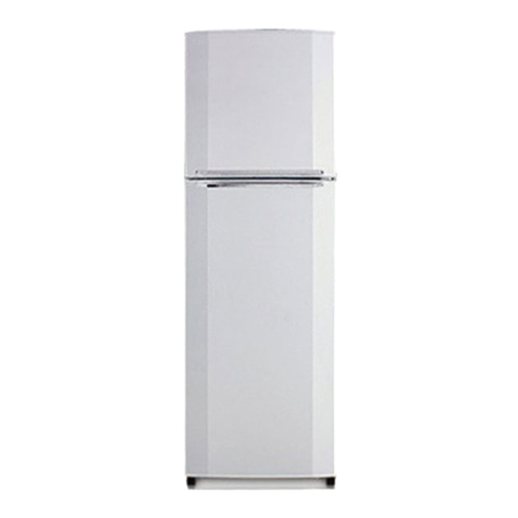
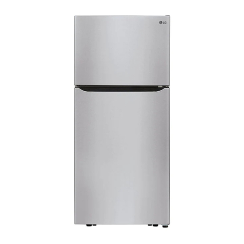
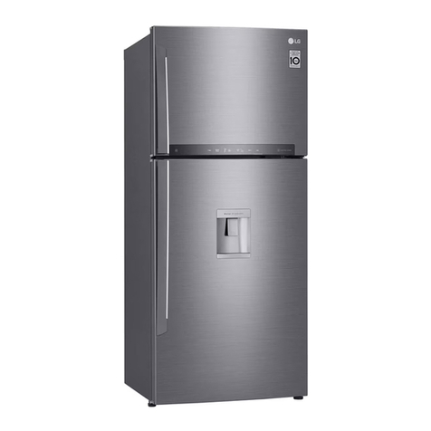
  9. LG GR-L247 and User manual

LG GR-L247 and User manual

This manual suits for next models

1

Other LG Refrigerator manuals

LG LFX21976ST User manual

LG

LG LFX21976ST User manual

LG GR-K30PS User manual

LG

LG GR-K30PS User manual

LG GML643PZ6F User manual

LG

LG GML643PZ6F User manual

LG GN-V312RLCA User manual

LG

LG GN-V312RLCA User manual

LG LFXS29626 User manual

LG

LG LFXS29626 User manual

LG GM-L261BNRY User manual

LG

LG GM-L261BNRY User manual

LG Refrigerator-freezer User manual

LG

LG Refrigerator-freezer User manual

LG LFXS30786 Series User manual

LG

LG LFXS30786 Series User manual

LG GR-B202SLC User manual

LG

LG GR-B202SLC User manual

LG LT18S2100 Series User manual

LG

LG LT18S2100 Series User manual

LG MFL68029533 User manual

LG

LG MFL68029533 User manual

LG GR-B762GLPW User manual

LG

LG GR-B762GLPW User manual

LG GN-M352RLCC User manual

LG

LG GN-M352RLCC User manual

LG SRSXB2622 Series User manual

LG

LG SRSXB2622 Series User manual

LG GR-M247QGMH User manual

LG

LG GR-M247QGMH User manual

LG GL-379 User manual

LG

LG GL-379 User manual

LG GN-B222SLC User manual

LG

LG GN-B222SLC User manual

LG GR-S632G R Series User manual

LG

LG GR-S632G R Series User manual

LG LSXS26326 User manual

LG

LG LSXS26326 User manual

LG GT50SGP User manual

LG

LG GT50SGP User manual

LG GR-W88FSK User manual

LG

LG GR-W88FSK User manual

LG GL-442 User manual

LG

LG GL-442 User manual

LG GR-151SPF  precaution User manual

LG

LG GR-151SPF precaution User manual

LG GR-S632GSU User manual

LG

LG GR-S632GSU User manual

Popular Refrigerator manuals by other brands

Frigidaire FRS26TS7DW2 Use & care manual

Frigidaire

Frigidaire FRS26TS7DW2 Use & care manual

Fisher Scientific 10ECEEFSA manual

Fisher Scientific

Fisher Scientific 10ECEEFSA manual

Summit FF22BDRSS user manual

Summit

Summit FF22BDRSS user manual

Frigidaire FFRU17B2QWE use & care

Frigidaire

Frigidaire FFRU17B2QWE use & care

Hotpoint ENBGH 19xxx FW operating instructions

Hotpoint

Hotpoint ENBGH 19xxx FW operating instructions

Hitachi R-SG28KPH instruction manual

Hitachi

Hitachi R-SG28KPH instruction manual

Dometic RMH 7390 L operating instructions

Dometic

Dometic RMH 7390 L operating instructions

AEG S71700TSW0 user manual

AEG

AEG S71700TSW0 user manual

Electrolux ENB3669 Instruction book

Electrolux

Electrolux ENB3669 Instruction book

Electrolux ERN 2930 Instruction book

Electrolux

Electrolux ERN 2930 Instruction book

Beko GNE 60520 X user manual

Beko

Beko GNE 60520 X user manual

Jenn-Air JUR248LBES00 Use & care guide

Jenn-Air

Jenn-Air JUR248LBES00 Use & care guide

Dometic RGE 4000 Installation and operating manual

Dometic

Dometic RGE 4000 Installation and operating manual

Dometic L-0191B Brochure & specs

Dometic

Dometic L-0191B Brochure & specs

Daewoo RN-33 Series user manual

Daewoo

Daewoo RN-33 Series user manual

Haier RF-8888-174 Service manual

Haier

Haier RF-8888-174 Service manual

Blaupunkt 5CK2 Series user manual

Blaupunkt

Blaupunkt 5CK2 Series user manual

Beko B5RCNE366HG user manual

Beko

Beko B5RCNE366HG user manual

manuals.online logo
manuals.online logoBrands
  • About & Mission
  • Contact us
  • Privacy Policy
  • Terms and Conditions

Copyright 2025 Manuals.Online. All Rights Reserved.

WARNINGS AND PRECAUTIONS FOR SAFETY
Please observe the following safety precautions in order to
use safely and correctly the refrigeretor and to prevent
accident and danger dunng repair.
1. Be care of an electric shock. Disconnect power cord
from wall outlet and wait for more than three minutes
before replacing PWI_ parts. Shut off the power
whenever replacing and repairing electric components.
2. When connecting power cord, please wait for more than
five minutes after power cord was disconnected from the
wall outlet.
3. Please check if the power plug is pressed down by the
refrigerator against the wall. If the power plug was
damaged, it may cause fire or electdc shock.
4. If the wall outlet is over loaded, it may cause fire. Please
use its own individual electrical outlet for the refrigerator.
5. Please make sure the outlet is properly earthed,
particularly in wet or damp area.
6. Use standard electrical components when replacing
them.
7. Make sure the hook is correctly engaged.
Remove dust and foreign materials from the housing
and connecting parts.
8 Do net fray. damage, machine, heavily bond, pull out,
or twist the power cord.
9. Please check the evidence of moisture intrusion in the
electrical components. Replace the parts or mask it
with insulation tapes if moisture intrusion was
confirmed.
10. Do not touch the icemaker with hands or tools to
confirm the operation of geared motor.
11. Do not let the customers repair, disassemble, and
reconstruct the refrigerator for themselves. It may
cause accident, electric shock, or fire.
12. Do not store flammable materials such as ether.
benzene, alcohol, chemicals, gas, or medicine in the
refrigerator.
13. Do not put flower vase, cup, cosmetics, chemicals,
etc., or container with full of water on the top of the
refrigerato_
14. Do not put glass bottles with full of water into the
freezer. The contents shall freeze and break the glass
bottles.
15. When you scrap the refrigerator, please disconnect the
door gasket first and scrap it where children are not
accessible.
-3-
I2002.08.24 245114,3
CIRCUIT DIAGRAM
BASIC DELUXE
"_'_ PWBASSEMBLY,MAIN "":'_" PWBASSEMBLY,MAIN
:1:
_W,4LL0_L_T
= m,u_11_ AISItW
m
!
|!
::5--c5-
PARTS IDENTIFICATION
4. Ref No. : GR-L247, GR-L207
Cover Hinge Cover PWB
\\
t-t t'_
Freezer Refrige_r
Compartme_ Compartm_t
Shelf
(optional)
Box
Shelf.=
(Steel,
T/Glass)
Drawer -
or Shelf
(optional)
Drawe
Shelf
Door rack
Conversion Switch
(Meats/Vegetables) Humidity Switch
drawer/Meat drawer
-15-
MICOM FUNCTION
1. Monitor Panel
1-t. GR-P247, GR-P207, GR-L247, GR-L207
Temperature adjustment button
for freezer compartment,
1-2. GR-C247, GR-C207, GR-B247, GR-B207
%.
- Temperatureadjustment button
for refrigerator compartment. Superfreezer.-
-- Temperature adjustment button
Loc for freezer compartment. Lock button. --
2. Description of Function
2-1-1. Funnction of Temperature Selection
Division Power Initially On 1st Press 2st Press 3th Press
Setting
]temperature
O
O
O
1-22"i
,1.......... ,
Q
1-23"i
Q O
4th Press
Q
Temperature Medium Medium Max Max Min Medium Min
Control
Freezer Control -19 °C -22 °C -23 °C -15 °C -17 °C
Refrigeration 3 °C 2 °C 0°C 6 °C 4 °C
Control
,t _o
The ICmpcralurecan _y :..3 C dependingon the load condition.
.P.Whenever pressing button, setting is repeated in the order of (Medium) ---*(Medium Max) --, (Max) --, (Min) -,
(Medium Min).
•The actual inner temperature varies depending on the food status, as the indicated setting temperature is a target
temperature, not actual temperature within refrigerator.
•Refrigeration function is weak in the initial time. Please adjust temperature as above after using refrigerator for minimum
2-3 days.
- 25-
MICOM FUNCTION
2-1-2. LCD Back Light Control
1. in order to easily view display status on the LCD, LCD Back Light is turned on for a minute in application of initial power,
for a minute in button manipulation and for a minute after closing time from opening time of door.
2. If pressing any display button once with the backlight turned off, buzzer rings and button function is not performed but
only backlight is turned on (If pressing the first button with the back light turned off, only back light ON function is
performed).
3. If pressing the special freezing button and the freezing temperature adjustment button for more than asecond, the back
light is turned on and all the graphics of LCD are turned on. If releasing the button, the LCD graphic is displayed in the
previous status and the back light is turned off (check LCD graphic and back light ONIOFF status).
2-I-3. Outside temperature display function
1. Outside temperature sensor at the left U of refrigerator senses ambient temperature and displays the outside temperature
in the left side of"Outside temperature" text on the LCD of the display part.
2. Ambient temperature is displayed up to -9°C ~ 49°C and displayed as "Lo" for less than -10°C and as "HI" for more than
50°C. If the ambient temperature sensor fails, it is displayed as "Er".
3. Since display temperature of outside temperature istemperature sensed by the ambient sensor in the hinge U of the
freezing room, it may differ from the outside temperature display of other household electrical appliances.
2-t-4. Lock function (display button lock)
1. In power application of refrigerator, the only "Release" text is turned on at the right side of lock graphic of LCD with the
lock release status.
2. If desiring to lock the display status and pressing the lock/release button once, "Release" text isturned off at the right side
of lock graphic of LCD and "Lock" text isturned on with lock status.
3. The only buzzer sound rings and function is not performed even if pressing display button other than lock/release key in
the lock status.
4. If desiring to release the lock status and pressing the lock/release button once, %ock" text is turned off at the right side of
lock graphic of LCD and =Release" text isturned on with lock release status.
2-2. Dispenser use selection
You can select water or ice.
Please select water, slice ice and square ice by pressing
button as you desire.
Please press the push button lightly by catching and pushing in cup.
•The border line isindicated for the selected function.
• "Tak!" sounds if 5seconds pass after ice comes out.
It issound that the outlet of ice is closed.
REFERENCE : Please wait for 2-3 seconds in order to take final ice
slices or drops of water when taking out cup from the
pressing switches after taking ice or water.
2-3. Automatic ice maker
• The automatic ice maker can automatically make 8 pieces of i(;e cube at a time, 80 pieces e day. But these quantities may
be varied according to various conditions including how many times the refrigerator door opens and closes.
•ice making stops when the ice storage bin is full.
•If you don't want to use automatic ice-maker, change the ice-maker switch to ON-OFF.
If you want to use automatic ice-maker again, change the switch to OFF-ON.
NOTE : It isnormal that a noise is produced when ice made is dropped fete the ice storage bin.
- 26 -
MICOM FUNCTION
2-4. When ice maker does not operate smoothly
lee is lumped together
• When ice is lumped together, take the ice lumps out of the ice storage bin, break them into small pieces, and then place
them into the ice storage bin again.
•When the ice maker produces too small or lumped together ice, the amount of water supplied to the ice maker need to
adjusted. Contact the service center.
If ice is not used frequently, it may lump together.
Power failure
•Ice may drop into the freezer compartment. Take the ice storage bin out and discard all the ice then dry it and place it
back. After the machine is powered again, crushed ice will be automatically selected.
The unit is newly installed
• Ittakesabout 12 hours for a newlyinstalledrefrigerator tomake ice in the freezer compartment.
2-5. Super freezer
Please select this function for prompt freezer.
•"On" or "OfF is repeated whenever pressing _ button,
• The arrow mark graphic remains at the On status after flickering 4 times when
selecting Special Refrigeration °On".
•Super freezer function automatically turns off if a fixed time passes.
2-6. Lock
This button stops operation of different button.
•Locking or Release is repeated whenever pressing the _).
-Pressing the other button when selecting 'LOCK', the button does not operate.
Ex) Inselecting Ex)Inselecting
"On" "Off"
Ex) In selec_ng Ex) Inselecting
2-7. Special freezing "LOCK" "LOCK"again
1. Special freezing is function to improve cooling speed of the freezing room by consecutively operating compressors and
freezing room fan. If pressing the special freezing button, °Turn Off" text of the LCD panel is turned off and "Turn On" is
immediately turned on end "Arrow (C)_graphic is turned on after flickedng once.
2. Special freezing is cycled in order of Selection/Release ("Turn On" / "Turn Oft") whenever pressing the selection button.
3. Special freezing is released if power failure occurs and then returns to the original status.
4. Temperature setting is not changed even if selecting the special freezing.
5. The change of temperature seWng at the freezing room or the cold storage room is allowed with special freezing selected
and processed.
6. The cold storage room operates the status currently set with special freezing selected end processed.
7. If selecting the special freezing, the special freezing function is released after continuously operating compressor and
freezing room fan.
8. If frost removal starting time is arrived during special freezing, special freezing operation is done only for the remaining
time after completion of frost removal when the special freezing operation time passes 90 minutes. If passing 90 minutes,
special freezing operation is done only for 2 hours after completion of frost removal.
9. If pressing special freezing button during frost removal, the special freezing LCD is turned on but if pressing the special
freezing, compressor operates after the remaining time has passed.
10. If selecting special freezing within 7 minutes (delay for 7 minutes of compressor) after the compressor stops,
compressor operates after the remaining time has passed.
11. The freezing room fan motor operates at the high speed of RPM during operation of special freezing.
- 27 -
MICOM FUNCTION
2-8. Control of variable type of freezing room fan
1. To increase cooling speed and load response speed, MICOM Vadably controls freezing room tan motor at the high speed
of RPM and standard RPM.
2. MICOM only operates in the input of initial power or special freezing operation or load response operation for the high
speed of RPM and operates in the standard RPM in other general operation.
3. If opening doors of freezing /cold storage room or home bar while fan motor in the freezing room operates, the freezing
room fan motor normally operates (If being operated in the high speed of RPM, it converts operation tothe standard
RPM). However, if opening doors of freezing room or home bar, the freezing room fan motor stops.
4. As for monitoring of BLDC fan motor error in the freezing room, MICOM immediately stops the fan motor by determining
that the BLDC fan motor is locked or poor if there would be position signal for more than 65 seconds at the BLDC motor.
Then it displays failure (refer to failure diagnosis function table) at the display part of refdgerator, perf_ms re-operatldn in
the cycle of 30 minutes. If normal operation is performed, poor status is released and refdgerator returns to the initial
status (reset).
2-9. Control of M/C room fan motor
1. The M/C room fan motor performs ON/OFF control by linking with the COMP.
2. It controls at the single RPM withe_ varying RPM.
3. Failure sensing method is same as in fan motor of fi-eezing fan motor (refer to failure diagnosis function table for failure
display).
2-10. Door opening alarm
1. Buzzer generates alarm sound if doors are not closed even when more than a minute consecutively has passed with
doors of freezing /cold storage room or home bar opened.
2. Buzzer rings three times in the interval of 0.5 second after the first one-minute has passed after doors are opened and
then repeats three times of On/Off alarm in the cycle of every 30 seconds.
3. if all the doors of freezing /cold storage room or home bar are closed dudng door open alarm, alarm is immediately
released.
Doors of freezing /C_ Opening
cold storage room
or home bar i i
BUZZER _A
Within Aminute
aminute
3Trnes 3T_nes313rues3"Sines
"i'30 i 30 i 30 1
secondssecondsseconds
_ Closing
2-11. Ringing of button selection buzzer
t. If pressingthe front displaybutton,"Ding ~" soundrings.
2-12. Ringing of compulsory operation, compulsory frost removal buzzer
1. If pressing the test button in the main PCB, "Phi ~" sound rings
2, In selecting compulsory operation, alarm sound is repeated and completed in the cycle of On for 0.2 second and Off for
1,8 second three times.
3, In selecting compulsory frost removal, alarm sound is repeated and completed in the cycle of On for 0,2 second, Off for
0,2 second, On for 0.2 second and Off for 1,4 second three times.
-28-
MICOM FUNCTION
2-13. Frost removal function
1. Frost removal is performed whenever total operation time of compressor becomes 7~7.5 hour.
2. In providing initial power (or returning power failure), frost removal starts whenever total operation time of compressor
becomes 4 ~ 4.5 hour.
3. Frost removal is completed if temperature of a frost removal sensor becomes more than 5°C after starting frost removal.
Poor frost removal is not displaced if it does not arrive at 5°C even if two hours have passed after starting frost removal.
4. No removal is done if frost removal sensor becomes poor (snapping or short-circuit).
2-14. Sequential operation of built-in product
Built-in products such as compressor, frost removal heater, freezing room fan, Cooling Fan and step motor damper are
sequentially operated as follows for preventing noise and part damage occurred due to simultaneous operation of alot of
parts in applying initial power and completing test.
Function Load Operation Sequence Remark
When temperature
of afrost removal
sensorbecomes
morethes 25°C
(in purchase,
rnovem_t)
J_ When
!_ temperature of a
5" frost removal
_sensorbecomes
less than 25°C
_'--" (In powerfalture,
"_ service)
Testmode1
(Compulsory
func_es)
Testmode 2
(Compulsoryfrost
removal)
m
--i
m
-- r I
0.5 , 0.3 F-FAN 0.3 STEP 0.3 HOME
POWER sec.! COMP sec. & ,sec. MOTOR sec. BAR
C-FAN DAMPER HEATER
ON ON ON ON ON
i
05! FROST 8FROST 0,3 HOME 5 iHOME
S_,
POWER REMOVAL _s_' REMOVAL_ BAR __ BAR
ON HEATER HEATER HEATER _EoA_R
ON OFF ON L
,WATER J--
l°'3 WATER 5 WATER 0.3 SUPPLY 50.3' F-FAN
sec & &TANK _- TANK sec sec. COMP _sec'
HEATER HEATER DISPENSE C-FAN
ON OFF HEATER ON ON
ON
--1 F
0.3 0,3 F-FAN 0.3 STEP
iTEST OTHER sec, COMP sec,
ISNV _LOAD -_ _&_;. MOTOR
(Press OFF ON C-FAN DAMPER
Once) ON OPEN
L
I,,"_
TEST COMP i0.3 F-FAN 0.3 FROST 0.3 STEP
sec,
S/W _ _ &_REMOVAL _MOTOR
(Press OFF C-FAN HEATER DAMPER
J2 times) OFF ON CLOSE
Ii
Iferror occurs
during operation,
initialoperation is
not done.
Ifpressing switch
once more in the
test reode 2 or
temperatureof a
frost removal
sensor iS more
than 5°C, it
immediataly
retems to the tesl
mode for initial
operation
COMP operates
after 7 minutes).
- 29 -
MICOM FUNCTION
2-15. Failure Diagnosis Function
1. Failure diagnosis function is function to facilitate service when nonconforming matters affecting performance of product
during use of product.
2. In occurrence of failure, pressing the function adjustment button does not perform function and only alarm sound ("Dtag-") nngs.
3. If nonconforming matters occurred are released during display of failure code, MICOM returns to the original state (Reset).
4. Failure code is displayed on the display part of setting temperature for the freezing room and the display part of setting
temperature for the cold storage room of LCD, which are placed at the display part of a refrigerator. All the LCD graphics
other than a failure code are turned off.
High quality type Basic type
(GR-P207,L20_ _) GR-C247,8247, C207,B207)
FailureCode F_tureCode
_spiayPart
O : Normal Operation
No. Item
1Failureof freezer
sensor
2 Fa_ureofr_
sersor1
3Fa_ueofre_
set.z2
4 Failureoffrost
removalsensor
5 Poorof frost
removal
6FSIlL_eofBLDCFAN
at_z_g room
7 FailureofBLDCFAN
at_rcem
8 Failure of
Communication
9Failureof
OutsideSensor
10 Failuraofice
r_mova]senaor
11 = Failureofioe
makerun_
Failurecodedisplaypad
So_ng
temp_ature_f0r
forfreezing ¢tl_0r_
Er FS
Er RB
Settingtemperature
display(Note 2)
Er DS
Er dH
Er FF
Er OF
Er CO
Selfingtemperature
display(Note 1)
Settingtemperature
display(Note2)
Se_ng temperature
display(Note2)
Contents of failure
Snappingof shott-drcultof
freezersensor
Snappingor shott_ircuit of
refrigeratorsensorI
Snappingor short-drcuit of
refiigerator sensor2
Snappingor shott-circuitoffrost
removal sensor
Snappingoffroat removalheater
or temperaturefuse, ppl_-oatof
connector(indkiated minimum4
hours afterfailureoccurs)
Poormotor,hookingofwiresto
fan,ContactofstructurestoFan.
Snappingorshort-circuitofL/wire
(ifthereisr_fanmotorsignalfor
mora_han60secnadsin
operationoffanmotor
Product operationstatus in failure
Freezer/_c-. Defrost Step_.ng
Cornp_ssor Fan Fan Heater n_u &la'_
J
_bl[_i'e_ Standard 0 O O
OFFbl_iV_ RPM
0 Standard 0 © O_l_l_._e,
0 Standard
RPM oC) o
OStandard O Nofrost
RPM removal o
0 Standard
RPM 000
o OFF(C_,_e_ 0 O O
O Standard _ (a_'_ O 0
RPM _ly30a'k_s)
0 Standard 0 0 0
RPM
Connection between mainPCB
anddisplayPCB. Snappingor
shorbdrsoit ofUwire.
Transmissionbetweenmain PCB
anddisplayPCB.Poor TR and
receMngpart
Snappingor sho_t-drcuitofoutside 0 0 0 0 0
temperatureppmeivingsensor
Snappingor short-circuitof ice- 00000
makingsensor
Psormot__-HSIlICwithinice.namer C) 0 0 0 0 --
unitSna_ng orshort.irruPtof
UWir&Po_ ma_I:_;Bd_,eci'cuit.
*In display of the failure mode, all LCDs of setting temperature for freezing/setting temperature for cold storage are turned
off (excluding Note1 and Note2).
- 30 -
MICOM FUNCTION
Note 1) In error of outside sensor, setting temperature for freezing/cold storage is normally displayed and indicated "Er" on
the outside temperature display part (normally displayed except for the outside temperature display part).
Note2) Nonconforming contents of poor R2 sensor, lee-making sensor and ice-making kit are displayed in LCD check, not
indicated on the failure display part (when pressing freezing temperature adjustment button and special freezing
button for asecond or more).
f old storage sensor 2
(middle partition)
c::::::°r [-'_ Normal : (C) Part LCD graphic- ON
Abnormal: Only (C) Pad LCD graphic-OFF
[_ Normal: (D) Part LCD graphic-ON
Abnormal: Only (D) Part LCD graphic-ON
[_ Normal: (E) Part LCD graphic-ON
Abnormal : Only (E) Part LCD graphic-ON
Other LCD graphics - ON
2-16. Test Function
1. The purpose of test function is to check function of the PWB and product and to search for the failure part at the failure
status.
2. Test button is placed on the main PCB of refrigerator (test switch), and the test mode will be finished after maximum 2
hours irrespective of test mode and then is reset to the normal status.
3. Function adjustment button is not perceived during performance of test mode but only warning sounds ring.
4. In finishing test mode, always pull the power cord out and then plag-in it again for the normal state.
5. If nonconforming contents such as sensor failure are found dudng performance of test mode. release the test mode and
display the failure code.
6. Even if pressing the test button during failure code display, test mode will not be performed.
Mode
Test 1
Test2
Manipulation
Press test button once
(freezing force mode)
Press test button once at
the test mode 1 status
(compulsory frost removal
mode)
Content
1. Continuous operation of compressor
2. Continuous operation of freezing room fan
(high speed RPM) end M/C room fan
3. Frost removal heater OFF
4. Full opening status (baffle opened) status of
electronic step motor damper
5. All display LCD graphics - ON.
1. Compressor OFF
2. Freezing room fan and M/C room fan is
turned off.
3. Frost removal heater ON
4. Full closing status (baffle closed) status of
electronic step motor damper
5. All display LCD graphics - OFF
((A) "Medium" status. (B) "Medium" status.
Only LCD is turned on)
Remarks
Freezing room fan is
turned off in door open.
Normal Press test button once at Return to the initial status. Compressor is operated
Status the test mode 2 status after 7 minutes.
(freezing force mode)
-31 -