LG LFX23961 Series User manual

CAUTION
BEFORE SERVICING THE UNIT,
READ THE SAFETY PRECAUTIONS IN THIS MANUAL.
REFRIGERATOR
SERVICE MANUAL
MODELS:
LFX23961**

CONTENTS
- 2 -
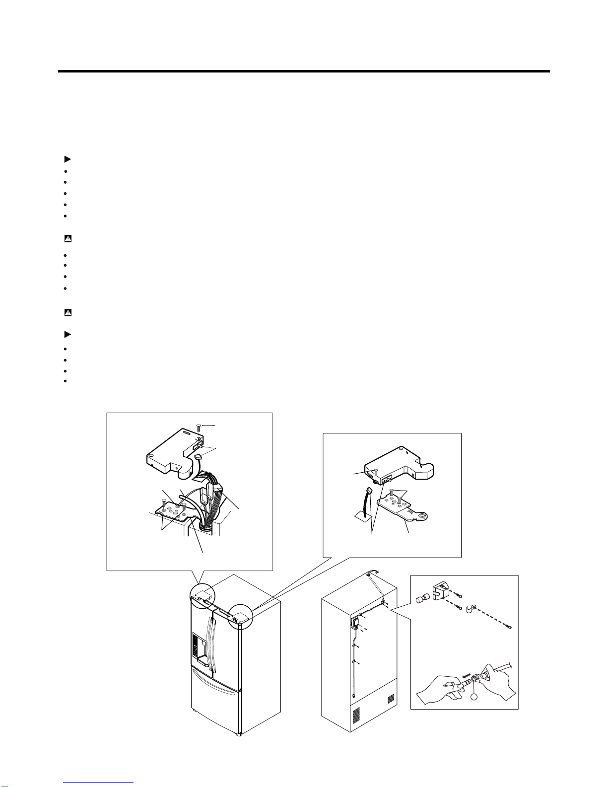
Please read the following instructions before servicing your
refrigerator.
1. Unplug the power before handling any elctrical
componets.
2. Check the rated current, voltage, and capacity.
3. Take caution not to get water near any electrical
components.
4. Use exact replacement parts.
5. Remove any objects from the top prior to tilting the
product.
SAFETY PRECAUTIONS
SAFETY PRECAUTIONS ............................................................................................................................
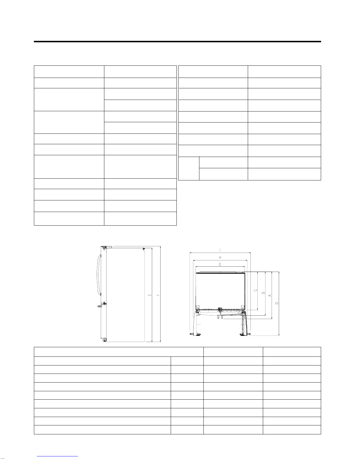
1. SPECIFICATIONS ...................................................................................................................................
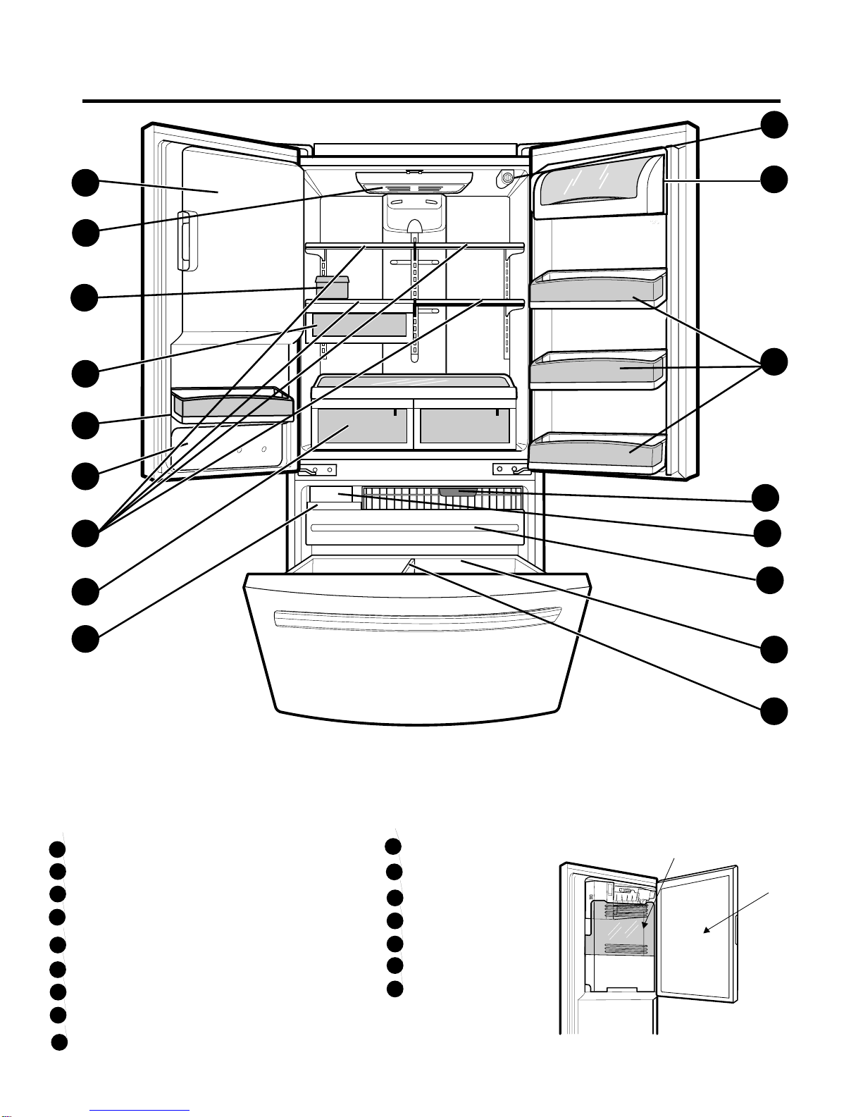
2. PARTS IDENTIFICATION ........................................................................................................................
3. DISASSEMBLY ........................................................................................................................................
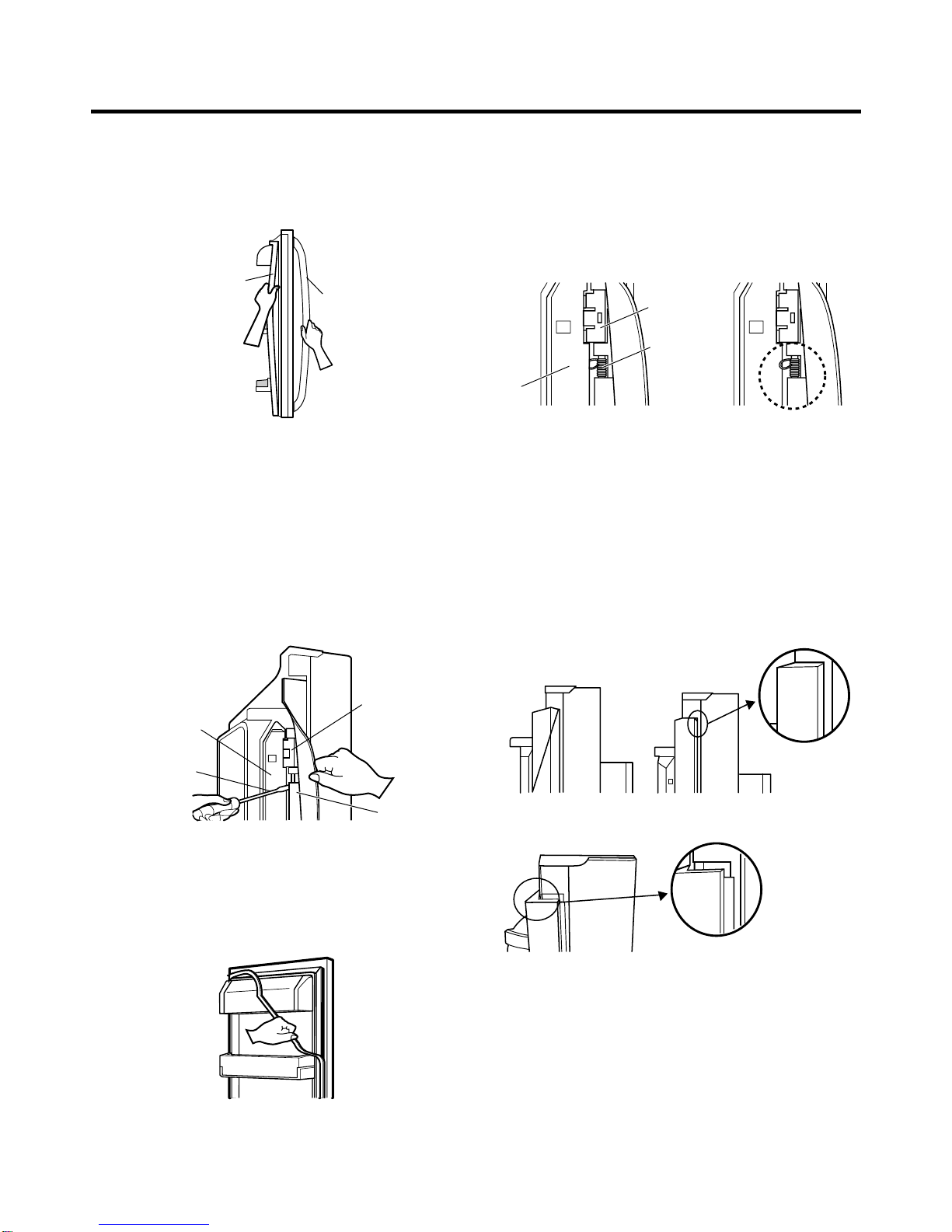
3.1 Door ....................................................................................................................................................
3.2 Door alignment ....................................................................................................................................
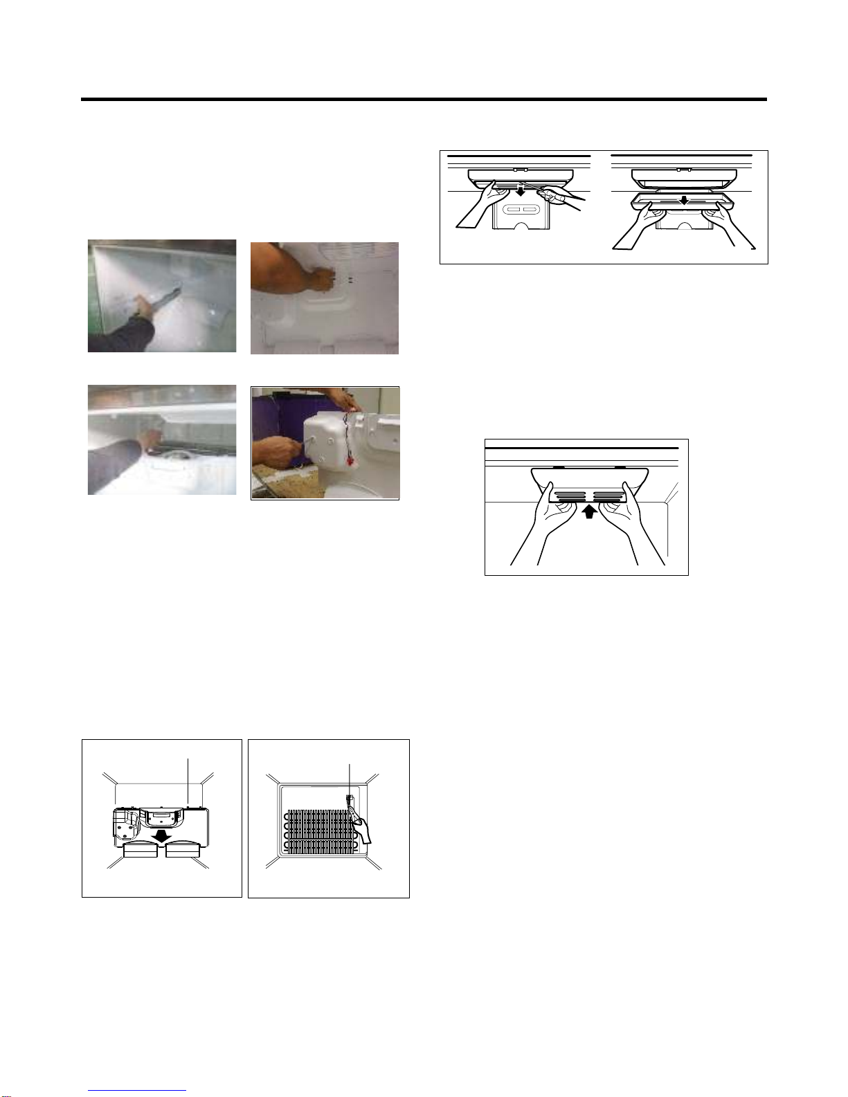
3.3 Fan and fan motor ...............................................................................................................................
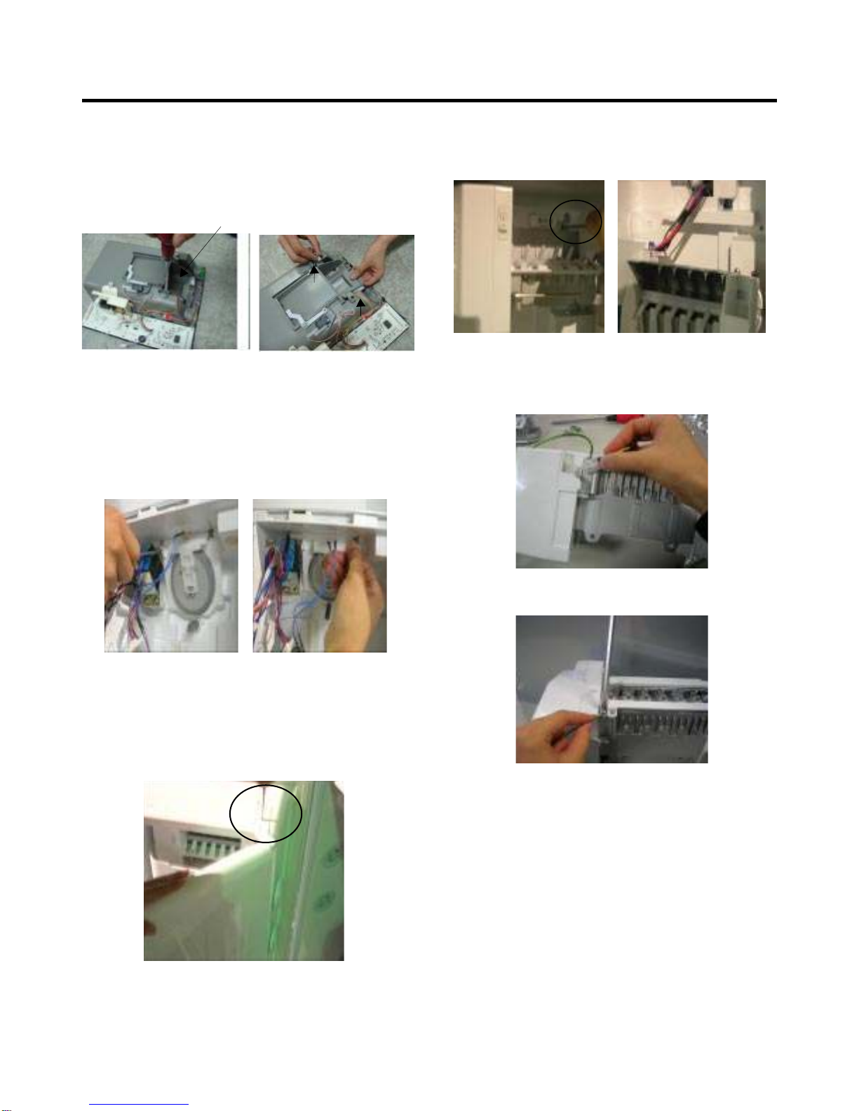
3.4 Defrost control assembly ....................................................................................................................
3.5 Lamp .......................................................................................................................................... .........
3.6 Multi duct .............................................................................................................................................
3.7 Main PWB.............................................................................................................................................
3.8 Display PCB.........................................................................................................................................
3.9 Ice button assembly ............................................................................................................................
3.10 Funnel replacement ...........................................................................................................................
3.11 Water button assembly ......................................................................................................................
3.12 Duct door replacement.......................................................................................................................
3.13 Ice corner door replacement .............................................................................................................
3.14 Icemaker assembly ...........................................................................................................................
3.15 Auger motor cover .............................................................................................................................
3.16 How to remove a door ice bin ............................................................................................................
3.17 How to insert a door ice bin ...............................................................................................................
3.18 How to remove and reinstall the pullout drawer ................................................................................
3.19 Fan and fan motor disassembly ........................................................................................................
3.20 Pull out drawer ..................................................................................................................................
4. ADJUSTMENT .........................................................................................................................................
4.1 Compressor .........................................................................................................................................
4.2 PTC-Starter .........................................................................................................................................
4.3 OLP (Overload Protector) ....................................................................................................................
4.4 To remove the cover PTC ....................................................................................................................
5. CIRCUIT DIAGRAM .................................................................................................................................
6. TROUBLESHOOTING .............................................................................................................................
6.1 Compressor and electrical components .............................................................................................
6.2 Other electrical components ...............................................................................................................
6.3 Service diagnosis chart ......................................................................................................................
6.4 Refrigeration cycle ..............................................................................................................................
7. OPERATION PRINCIPLE AND REPAIR METHOD OF ICEMAKER ......................................................
7.1 Operation principle .............................................................................................................................
7.2 Ice maker functions ............................................................................................................................
7.3 Defect diagnosis function ...................................................................................................................
8. DESCRIPTION OF FUNCTION & CIRCUIT OF MICOM .........................................................................
8.1 Function ..............................................................................................................................................
8.2 PCB function .......................................................................................................................................
8.3 Troubleshooting .................................................................................................................................
8.4 Main PWB assembly and parts list .....................................................................................................
9. EXPLODED VIEW AND REPLACEMENT PART LIST ...........................................................................
2
3
4
5
5
7
7
8
8
9
9
9
9
9
10
10
10
10
11
12
12
13
15
15
16
16
16
17
17
18
19
19
20
21
22
24
24
25
26
27
27
33
38
40
43

1. SPECIFICATIONS
- 3 -
ITEMS SPECIFICATIONS
DOOR DESIGN Side Rounded
DIMENSIONS (inches)
35 3/4X 30 X 69 3/4(WXDXH) 21cu.ft
35 3/4X 34 1/4X 69 3/4(WXDXH) 25cu.ft
NET WEIGHT (pounds) 302.58 (
21cu.ft)
324.18 (
25cu.ft)
COOLING SYSTEM Fan Cooling
TEMPERATURE CONTROL Micom Control
Full Automatic
DEFROSTING SYSTEM Heater Defrost
DOOR FINISH Embossed Metal, VCM, Stainless
HANDLE TYPE Bar
INNER CASE ABS Resin
INSULATION Polyurethane Foam
ITEMS SPECIFICATIONS
VEGETABLE TRAY Opaque Drawer Type
COMPRESSOR Recipro
EVAPORATOR Fin Tube Type
CONDENSER Wire Condenser
REFRIGERANT R-134a (120 g)
LUBRICATING OIL ISO7 (310 ml)
DEFROSTING DEVICE SHEATH HEATER
LAMP REFRIGERATOR LED Module(12)
FREEZER LED Module(3)
Description LFX21980ST LFX25980ST
Depth w/ Handles A 30 in. 34 1/4 in.
Depth w/o Handles B 27 1/2 in. 31 3/4 in.
Depth w/o Door C 23 5/8 in. 27 7/8 in.
Depth (Total with Door Open) D 42 1/4 in. 46 1 /2 in.
Height to Top of Case E 68 3/8 in. 68 3/8 in.
Height to Top of Door Hinge F 69 3/4 in. 69 3/4 in.
Width G 35 3/4 in. 35 3/4 in.
Width (door open 90 deg. w/o handle) H 39 1/4 in. 39/1/4 in.
Width (door open 90 deg. w/ handle) I 44 1/4 in. 44 1/4 in.
DIMENSIONS

2. PARTS IDENTIFICATION
- 4 -
Refrigerator Light
Filter (Inside)
Modular Door Bins
Refrigerator Shelves
Crisper
Ice Room
Glide out Drawer
Turbo Motor
A
B
H
P
O
G
N
J
K
I
C
E
C
D
F
M
L
Use this page to become more familiar with the parts and features. Page references are included for your convenience.
NOTE: This guide covers several dierent models. The refrigerator you have purchased may have some or all of the
items listed below. The locations of the features shown below may not match your model.
A
B
C
F
G
H
I
J
Durabase
Freezer light
Divider
Ice Bin
Water Tank Cover
Snack Pan
Dairy Bin
Egg box
L
K
M
N
O
P
E
D
Ice Bucket
Ice Room Door
*On some models

3. DISASSEMBLY
- 5 -
3-1DOORS
(7)
(1)
(8)
(2)
1. Removing Refrigerator Door
NOTE: Handle appearance may vary.
IMPORTANT: Before you begin, turn the refrigerator OFF and unplug it. Remove food and any bins from doors.
Left Door
Disconnect water supply tube by pushing back on the disconnect ring (3).
Loosen the screws and remove the cove on back side (see figure A).
Loosen the cover screw (1).
Disconnect door switch wire (2).
Pull out the tube (4).
CAUTION: If a tube end is deformed or worn out, cut the damaged portion away.
Disconnect wire harness (5).
Remove the ground screw (6).
Loosen screws (7) and lift off the top hinge (8).
CAUTION: When removing top hinge, be careful that the door does not fall forward.
Right Door
Loosen the cover screw (1).
Disconnect door switch wire (2).
Place the door on a non-scratching surface with the inside up.
Loosen screws (7) and lift off the top hinge (8).
Place the door on a non-scratching surface with the inside up.
Figure A
3
(1)
(2)
(7)
(5)
(6) (4)
(8)

- 6 -
Door Gasket Removal
1. Remove door frame cover
Starting at top of cover and working down, snap cover
out and away from door.
2. Remove gasket bracket clips
There are two clips on each door. Start bracket removal
near one of the middle clips.
1) Pull gasket back to expose gasket bracket clip and
door frame.
2) Insert a flat tip screwdriver into seam between gasket
bracket and door frame and pry back until clips snap
out.
3) Continue prying back along seam until all clips snap
out.
3. Remove gasket
Pull gasket free from gasket channel on the three
Door Gasket Replacement
l
remaining sides of door.
1. Insert gasket bracket clips
1) Insert gasket bracket edge beneath door frame edge.
2) Turn upper gasket bracket spring so that the spring
ends are in the door channel.
3) Push in clip until you hear it snap securely into place.
4) Push in remaining clip until you hear it snap securely
into place.
Note: Make sure that no part of gasket bracket edge
protrudes from beneath door frame edge.
2. Insert gasket into channel
1) Snap gasket assembly into the door bracket.
<Inserting the Gasket Assembly into the Bracket Door>
Frame Cover Handle
Door
Frame
Gasket
Bracket Clip
Flat Tip
Screwdriver
Gasket
Bracket
Figure 1
Figure 2
Figure 3
Door
Frame
Gasket
Bracket Clip
Spring
IncorrectCorrect
Incorrect
Correct
Figure 4
Figure 5

- 7 -
2) Press gasket into channels on the three remaining
sides of door.
3. Replace door frame cover
Starting at top of cover and working down, snap cover
back into door.
3-2 DOOR ALIGNMENT
If fridge door are uneven,
• Use the wrench (Included with the User Manual) to
adjust the bolt in the door hinge to adjust the
height.(CCW to raise or CW to lower the height.)
Figure 6
Figure 8
Figure 7
Figure 9
3-3 FAN AND FAN MOTOR(EVAPORATOR)
1. Remove the freezer shelf. (If your refrigerator has an
icemaker, remove the icemaker first)
2. Remove the plastic guide for slides on left side by
unscrewing phillips head screws.
3. Remove the grille by pulling the grille fan forward.
4. Remove the Fan Motor assembly by loosening 2 screws
and disassembling the shroud.
5. Pull out the fan and separate the Fan Motor and Bracket.
GRILLE
FAN MOTOR
FAN
BRACKET
MOTOR

* Ice Fan Scroll Assembly Replacement
1) Remove the plastic guide for slides on left side by
unscrewing phillips head screws.
2) Pull the grille forward as shown in the second picture.
3) Disconnect wire harness of the grille
4) Remove the scroll assembly by loosening 3 screws
3-4 DEFROST CONTROL ASSEMBLY
Defrost Control assembly consists of Defrost Sensor and
FUSE—M.
The Defrost Sensor works to defrost automatically. It is
attached to the metal side of the Evaporator and senses its
temperature. At 72¡C, it turns the Defrost Heater off.
Fuse-M is a safety device for preventing over-heating of
the Heater when defrosting.
1. Pull out the grille assembly. (Figure 10)
2. Separate the connector with the Defrost Control
assembly and replace the Defrost Control assembly
- 8 -
Figure 10
DEFROST-CONTROL
ASSEMBLY
Figure 11
(1) (2)
(3) (4)
3-5 LAMP
3-5-1 Refrigerator Compartment Lamp
1. Unplug Refrigerator, or disconnect power at the circuit
breaker.
2. If necessary, remove top shelf or shelves.
3. Using a flat instrument, gently pry the cover loose in the
front as shown. Rotate downward to remove rear tabs.4.
Make sure the bulbs are cool to the touch.
Turn bulbs counterclockwise to remove.
5. Assemble in reverse order by snapping the Lamp Cover
in, engaging the rear tabs followed by the front tabs.
(Max. 40 W-2EA)
3-5-2 Freezer Compartment Lamp
1. Unplug refrigerator power cord form outlet.
2. Gently pry the lamp cover loose in the back
as shown. Rotate forward to remove the
front tabs.
3. Make sure the bulb is cool to the touch. Turn the
bulb counterclockwise to remove.
4. Replace with a new 40-watt appliance bulb.
5. Insert tabs on front of cover into slots in freezer
ceiling. Push cover up to snap back into place.
Figure 13
Figure 12
GRILLE ASSEMBLY

3-6 MULTI DUCT
1. Remove the upper and
lower Caps by using a flat
screwdriver, and remove
2 screws. (Figure 16)
2. Disconnect the lead wire
on the bottom position.
3-7 MAIN PWB
1) Loosen the 3 screws on the PWB cover.
2) Remove the PWB cover
3) Disconnect wire harness and replace the main PWB in
CAUTION: When replacing the dispenser cover in the
reverse order of removal, be careful that the lead wire
does not come out and the water tube is not pinched by
the dispensor,
3-8 DISPLAY PCB
As shown below, remove 1 case PCB fixing screw.
Remove the display PCB fixing screw.
3-9 ICE BUTTON ASSEMBLY
1) Remove the screw fixing the button lever.
2) Push the spring from the hanging hook to remove it.
3) Apply some pressure to the rib in direction and lift the
button in Direction.
3-10 FUNNEL REPLACEMENT
Pull down and forward.
Figure 14
Case, PCB Display PCB
Button Lever
- 9 -
1) Pull out the darin 2) Grasp the lower
part of the dispenser
firmly ,pull it out.
3) Hold the inner side
of cover dispenser
with both hands at the
handle side to pull it
out forward.
4) If nozzle is interfered with button , push and
pull out the bottom of button. 5) Remove the
connected part of
Lead wire.

3-11 WATER BUTTON ASSMEBLY
1) Romove screws.
2) Grasp the Button assembly and lift up.
3-12 DUCT DOOR REPLACEMENT
1) Pull up and out on the dispenser cover to remove.
2) Disconnect the wire harness.
3) Remove the funnel
4) Replace in reverse order.
3-13 ICE CORNER DOOR REPLACEMENT
1) Loosen the front screw as shown in the picture.
2) Lift up the hinge with one hand.
3-14 ICEMAKER ASSEMBLY
1) Loosen two screws as shown in the first picture.
3) Pull out the Ice Corner Door with the other hand.
2) Disconnect the wire harness & ground screw replace
theIcemaker assembly in the reverse order of removal.
3) It separates a ground connection screw.
Button Lever
hinge
- 10 -

3-15 AUGER MOTOR COVER
1) After removing the icemaker remove the (5) stainless
screws holding the auger motor cover, shown in the
picutres below.
2) Grip the bottom of motor cover assembly and pull out it.
3) Disconnect wire harness of motor cover assembly.
There is a auger motor on the back, as shown in the
picture.
Auger Motor
- 11 -

3-16 HOW TO REMOVE A DOOR ICE BIN
1) Grip the handles, as shown in the picture.
2) Lift the lower part slightly.
3-17 HOW TO INSERT A DOOR ICE BIN
1) Insert the Ice Bin, slightly tilting it to avoid touching the
3) Take the Ice Bin out slowly.
Icemaker. (especially, ice maker lever)
Insert the ice bucket carefully avoid contacing the
automatic shut off arm.
- 12 -
1
2

3-18 HOW TO REMOVE AND REINSTALL THE PULLOUT DRAWER
3-19-1 Follow Steps to Remove
Step 1) Open the freezer door.
Step 3) Remove the two screws from the guide rails (one
from each side).
Step 2) Remove the lower basket.
Step 4) Lift the freezer door up to unhook it from the rail
support and remove.
Pull both rails to full extension.
Step 5) First: Remove the gear from the left side first by releasing the tab behind the gear, place a screwdriver between the
gear and the tab and pull up on the gear.
Second: Remove the center rail.
Third: Remove the gear from the right side by following the same steps for the left side.
NOTE: THIS TAB MUST BE PUSHED IN TO RELEASE THE GEAR.
- 13 -

3-18-2 Follow Steps to Reinstall
Step 1) Reinstall the right side gear into the clip.
Step 2) Insert the rail into the right side gear. Gears do not
need to be perpendicular to each other.
Step 4) The rail system will align itself by pushing the rails
all the way into the freezer section.
Pull the rails back out to full extension.
Step 6) Reinstall the two screws into the guide rails
(one from each side).
Step 3) Insert the rail into the left side gear, and insert the
gear into the clip.
Step 5) Reinstall the freezer door by inserting the rail tabs
into the guide rail.
Step 7) Reinstall the lower basket, and close the freezer
door.
- 14 -

DRAIN PIPE ASSEMBLY and one connected to the
1) Using a short screwdriver, loosen one SCREW in
MOTOR COVER.
2) Pull and separate the FAN ASSEMBLY and MOTOR
turning counterclockwise based on the MOTOR SHAFT.
The assembly is in the reverse order of the disassembly
and take special care for the following details.
1. Be careful not to bend the tube during assembly.
2. Press the WATER DISPENSER button until water pours
out and check for leakage in the CONNECTOR TUBE (It
differs by the water pressure but usually takes about 2
minutes until water pours out.)
®
®
MOTOR COVER
FAN ASSEMBLY MOTOR
- 15 -
3-19 FAN AND FAN MOTOR DISASSEMBLY
METHOD 3-20 PULL OUT DRAWER
To remove, lift basket up and pull out straight out.
2.
1.
To Install, pull both rails out to full extension.
Hook the basket supports into the rail tabs and push to
the back of compartment.
1
2

- 16 -
4-1 COMPRESSOR
4-1-1 Role
The compressor intakes low temperature and low pressure
gas from the evaporator of the refrigerator and compresses
this gas to high-temperature and high-pressure gas. It then
delivers the gas to the condenser.
4-1-2 Composition
The compressor includes overload protection. The PTC
starter and OLP (overload protector) are attached to the
outside of the compressor. Since the compressor is
manufactured to tolerances of 1 micron and is hermetically
sealed in a dust and moisture-free environment, use
extreme caution when performing repairs.
4-1-3 Note for Usage
(1) Be careful not to allow over-voltage and over-current.
(2) If compressor is dropped or handled carelessly, poor
operation and noise may result.
(3) Use proper electric components appropriate to the
Particular Compressor in your product.
(4) Keep Compressor dry.
If the Compressor gets wet (in the rain or a damp
environment) and rust forms in the pin of the Hermetic
Terminal, poor operation and contact may result.
(5) When replacing the Compressor, be careful that dust,
humidity, and soldering flux donÕt contaminate the inside
of the compressor. Dust, humidity, and solder flux
contaminate the cylinder and may cause noise,
improper operation or even cause it to lock up.
4-2 PTC-STARTER
4-2-1 Composition of PTC-Starter
(1) PTC (Positive Temperature Coefficient) is a no-contact
semiconductor starting device which uses ceramic
material consisting of BaTiO3.
(2) The higher the temperature is, the higher the resistance
value. These features are used as a starting device for
the Motor.
4-2-2 Role of PTC-Starter
(1) The PTC is attached to the Sealed Compressor and is
used for starting the Compressor Motor.
(2) The compressor is a single-phase induction motor.
The starting operation, the PTC allows current flow to
both the start winding and main winding.
4-2-3 PTC-Applied Circuit Diagram
l Starting Method for the Motor
4-2-4 Motor Restarting and PTC Cooling
(1) It requires approximately 5 minutes for the pressure to
equalize before the compressor can restart.
(2) The PTC device generates heat during operation.
Therefore, it must be allowed to cool before the
compressor can restart.
4-2-5 Relation of PTC-Starter and OLP
(1) If the compressor attempts to restart before the PTC
device is cooled, the PTC device will allow current to
flow only to the main winding.
(2) The OLP will open because of the over current
condition. This same process will continue (3 to 5
times) when the compressor attempts to restart until
the PTC device has cooled. The correct OLP must be
properly attached to prevent damage to the
compressor.
Parts may appear physically identical but could have
different electrical ratings. Replace parts by part
number and model number. Use only approved
substitute parts.
4-2-6 Note for Using the PTC-Starter
(1) Be careful not to allow over-voltage and over-current.
(2) Do not drop or handle carelessly.
(3) Keep away from any liquid.
If liquid such as oil or water enters the PTC,
PTC materials may fail due to breakdown of their
insulating capabilities.
(4) If the exterior of the PTC is damaged, the resistance
value may be altered. This can cause damage to the
compressor and result in a no-start or hard-to-start
condition.
(5) Always use the PTC designed for the compressor and
make sure it is properly attached to the compressor.
Parts may appear physically identical but could have
different electrical ratings. Replace parts by part
number and model number. Use only approved
substitute parts.
PTC STARTER SEALED
TERMINAL
COMPRESSOR
MOTOR
C
M
SM
S
N
L1
OVERLOAD PROTECTOR
Resistance Starter Capacitor Running
PTC
22
LFX21980**
LFX25980**
3 2 5 6
2 3 6 5
4. ADJUSTMENT

- 17 -
4-3 OLP (OVERLOAD PROTECTOR)
4-3-1 Definition of OLP
(1) OLP (OVERLOAD PROTECTOR) is attached to the
Compressor and protects the Motor by opening the
circuit to the Motor if the temperature rises and
activating the bimetal spring in the OLP.
(2) When high current flows to the Compressor motor, the
Bimetal works by heating the heater inside the OLP,
and the OLP protects the Motor by cutting off the
current flowing to the Compressor Motor.
4-3-2 Role of the OLP
(1) The OLP is attached to the Sealed Compressor used
for the Refrigerator. It prevents the Motor Coil from
being started in the Compressor.
(2) For normal operation of the OLP, do not turn theAdjust
4-4 TO REMOVE THE COVER PTC
(1) Remove the Cover Back M/C.
Screw of the OLP in any way. (2) Disconnect two housing upper side of comp connected
in.
(3) Loosen two screws on comp base.
(4) Use a L-shaped flap tool to pry off the cover.
(5) Assembly in reverse order of disassembly.
Part
Customer part
number
Lot code/
date code
330 FBYY -S1 BOX98
12345678
Physical
termination
part number
Electrical
characteristics
part number
No. Name
Base, phenolic
(UL 94 V-0 rated)
Movable arm support, plated steel
Stationary contact support,
plated steel
Heater support, plated steel
Heater, resistance alloy
Disc, thermostatic alloy
Movable arm, spring temper
copper alloy
Contact, movable, silver on copper
Contact, stationary, silver on copper
Slug, plated steel
Cover, polyester
(UL 94 V -0 rated)
Pin connector, plated copper alloy
(To engage 2.33/2.66 mm dia. pin)
Quick-connect terminal, brass,
conforms to UL 310, MEMA
DC-2, DIN 46344
(OVERLOAD PROTECTOR cross section)
Figure 19
2
3
1

5. CIRCUIT DIAGRAM
- 18 -
BK
WH
BL
BO
BLBL
BN
PR
WH
BK
YL
BL
BN
BN
RD
BL
BN
WH/BK
BL
WH
WH
BO
BO
SB
SB
RD
YL
BK
BL
BO
BO
RD
BK
GY
GY
BO
SB
BN
BL
RD
PR
BK
WH
BO
RD
BK
BL
BL
RD
BN
WH/BK
BO
C-FAN
F-FAN
ICING
F-FAN
R-DOOR S/W
STEPPING
MOTOR
F-DOOR S/W
D-SENSOR
R-SENSOR
F-SENSOR
WH/RD BL/WH
SB YL PKWH GY BOBL RD BKBN
WH/BK
SB WH GY BOBL RD BKBN
WH/BK
PK BL WH YL GY PRRD BK SB
WH BO RD BL YL BN SB PK
RD BL YL BN
F-LAMP
FD-HEATER
R-LAMPS THERMOSTAT
FUSE-M
HEATER SHEAT
ICING-SENSORRT-SENSOR
(72°C)
FRONT HEATER
CON101 CON103
CON102
LD COMP’
MQ COMP’ EG COMP’

6. TROUBLESHOOTING
- 19 -
6-1 COMPRESSOR AND ELECTRIC COMPONENTS
1
2
3
4
5
2
5
5
3
5
1
43
YES
NO
YES
The range of resistance is between 1~50½(ok)
Open or short
YES YES
NO
NO
Power Source.
No Voltage.
(Rated Voltage
–10%)?
Replace OLP.
Reconnect.
Reference Page12.
Reference Page12.
Did
compressor
start?
Compressor
is OK
Replace the
compressor
Check connection
condition.
OLP disconnected?
Advise customer that
power supply needs to be
checked by an electrician.
Replace
Compressor.
Supply
voltage rating
with –10%.
Applied voltage isn’t
in acceptable range.
(115V –10%)
Remove PTC-Starter
from Compressor and
measure voltage
between Terminal C of
Compressor and
Terminal 5 or 6 of PTC.
Check resistance
between M-C, S-C and
M-S in Motor
Compressor.
Check resistance of
two terminals in
PTC-Starter.
Check resistance of two
terminals in OLP.
Check the power supply
under load.
(Compressor attempting
to re-start after being off
for 5 minutes).
Check
resistance of
Motor
Compressor.
Check
resistance of
PTC-Starter.
Check OLP.
Check
starting state.

- 20 -
•Not cooling at all
tPoor cooling performance
Compressor
doesn’t run.
Compressor runs
poorly. Check starting
voltage.
Check for open short or
incorrect resistance readings
in the following components
a. Starting devices
b. OLP
c. Compressor coil
d. Wiring harness
Low voltage.
Short, open, or broken.
Poor contact
or shorted.
Coil open or shorted.
Poor contact
or shorted.
Poor or broken or
open contact.
Shorted.
Lack of capacity.
Replace
indicated component.
Advise customer that
the Power supply
needs to be checked
by an electrician.
Replace
indicated component.
Cause
Check voltage at
starting devices.
Check current flowing
in sub-coil of
Compressor.
Check rating of OLP.
Fan motor
doesn’t run.
Heavy frost buildup on
EVAPORATOR.
Wire is open or
shorted.
Coil is shorted
or open.
Open.
Open. Replace
Defrost Heater.
Replace
indicated component.
Replace
indicated component.
Check wiring circuit.
Check Fan Motor.
Check current flow in
the following
components:
Sensor
Fuse-M
Check current flow in
6-2 OTHER ELECTRICAL COMPONENTS
the Defrost Heater.
Other manuals for LFX23961 Series
5
This manual suits for next models
2
Table of contents
Other LG Refrigerator manuals

LG
LG LFXS28596 series User manual

LG
LG LMX25981SB - 24.7 cu. Ft Refrigerator User manual

LG
LG LFC20740 Series User manual

LG
LG GN-C702SGGU User manual

LG
LG G 201 Series User manual

LG
LG SXS Refrigerator User manual

LG
LG GWL227HBQA User manual

LG
LG GF-Q5143GE User manual

LG
LG GR-K18PBS User manual

LG
LG GC-P207BLX User manual