LG LFX23961SW /01 User manual

MODELS:
LFX23961SW /01
LFX23961ST /01
LFX23961SB /01
CAUTION
BEFORE SERVICING THE UNIT,
READ THE SAFETY PRECAUTIONS IN THIS MANUAL.
REFRIGERATOR
SERVICE MANUAL

CONTENTS
SAFETY PRECAUTIONS ...................................................................................................................................
1. SPECIFICATIONS ...........................................................................................................................................
2. PARTS IDENTIFICATION ...............................................................................................................................
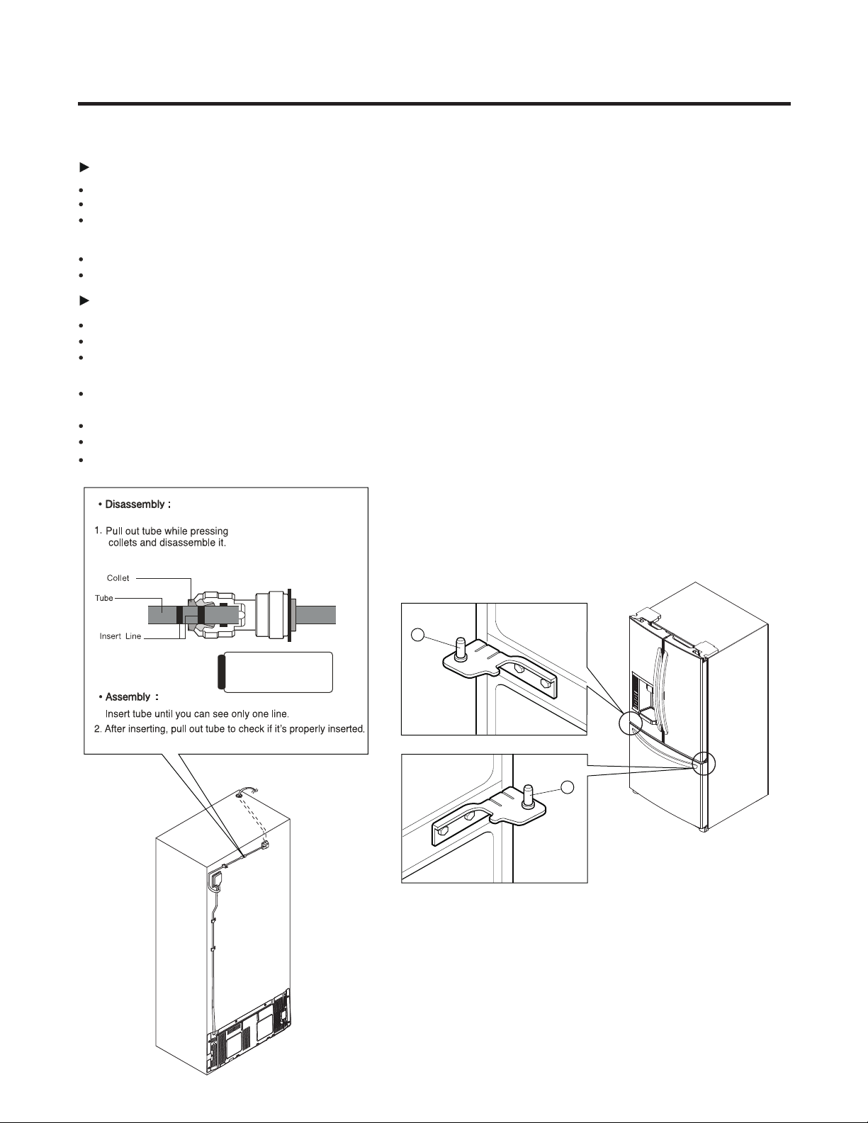
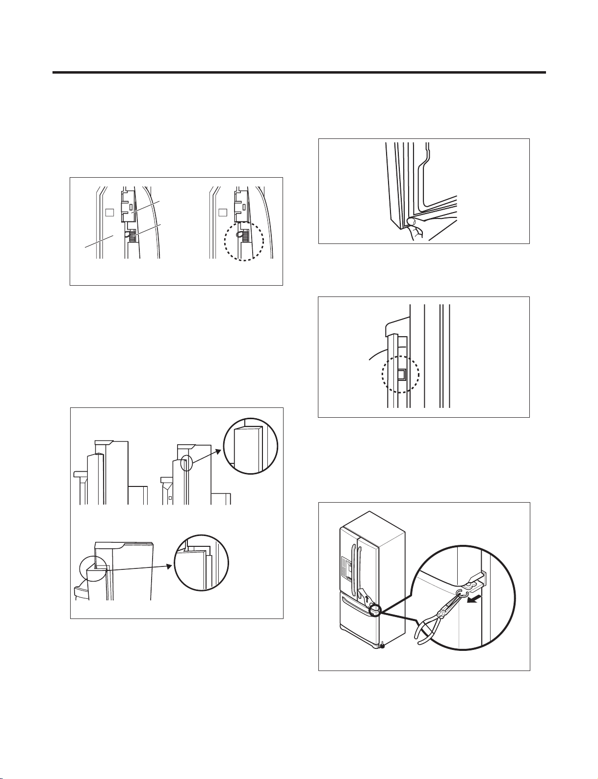
3. DISASSEMBLY ...............................................................................................................................................
4. ADJUSTMENT ................................................................................................................................................
5. CIRCUIT DIAGRAM ........................................................................................................................................
6. TROUBLESHOOTING ....................................................................................................................................
7. OPERATION PRINCIPLE AND REPAIR METHOD OF ICEMAKER .............................................................
8. DESCRIPTION OF FUNCTION & CIRCUIT OF MICOM ................................................................................
9. EXPLODED VIEW ..........................................................................................................................................
2
3
4
5
17
19
20
25
28
43
Please read the following instructions before servicing your
refrigerator.
1.Check the refrigerator for current leakage.
2.To preven telectric shock,unplug before servicing.
3.Always check line voltage and amperage.
4.Use standard electrical components.
5.Don't touch metal products in the freezer with wet
Hands.This may cause frost bite.
6.Prevent water from spiling on to electric elements or the
Machine parts.
7.Before tilting the refrigerator,remove all materials from
On or in the refrigerator.
8.When servicing the evaporator,wear gloves to prevent
Injuries from the sharp evaporator fins.
9.Service on the refrigerator should be performed by a
Qualified technician.Sealed system repair must be
Performed by a CFC certified technician.
SAFETY PRECAUTIONS
- 2 -

1. SPECIFICATIONS
- 3 -
LFX23961SW LFX23961ST LFX23961SB
Super White Stainless Black
PCM Stainless VCM
FREEZER
Basket, Quantity
Tray meat
Ice Tray & Bank
Tray Drawer F/L
Egg Bank
Lamp
Shelf
Tray Drawer F/U Yes (Full Width)
Yes (Plastic)
REFRIGERATOR
Case Material
Door Material
Handle Type
Display Graphic
Lamp
Shelf
Polyol Ester (POE) 310± 10cc
Insulation
Compressor
Basket, Quantity
Anti-freezing Heater
Drier
Defrost Cycle
Desfrosting Device
Evaporator
Capillary Tube
First Defrost
Condenser
Lubricanting Oil
Defrosting System
Cooling System
Rated Rating
Climate class
Full Automatic
MODELS
SPECIFICATIONS
Capacity
Refrigerant
Net Weight
Dimensions
GENERAL FEATURES
Color
Temperature Control
Temperate (N)
115V~ / 60Hz
Fan Cooling
MICOM control
892 (W) x 925 (D) x 1860 (H) mm
124kg
23 cuft
R134a (120gr)
Heater Defrost
Cyclo, Pentane
Fin Tube Type
Wire Condenser
LD72LACM PTC Starting Type
MOLECULAR SIEVE XH-7
ID Ø0.75
4 Hours
7 - 40 Hours
Heater, Sheath
Water Tank Heater
Embo (normal)
Vista
Yes (1) 40W/Blue
No
ICE PLUS
1 left + 3 right
AUTO ICE MAKER
Yes (2) 40W/Blue
4 Fix
Yes
No
No

2. PARTS IDENTIFICATION
- 4 -
B
D
F
G
H
J
P
O
A
K
I
M
L
N
E
C
E
Use this page to become more familiar with the parts and features. Page references are included for your convenience.
NOTE: This guide covers several dierent models. The refrigerator you have purchased may have some or all of the
items listed below. The locations of the features shown below may not match your model.
Ice Bucket
Ice Room Door
*On some models
AJ
Refrigerator Light Dairy Bin
Freezer Light
Turbo Motor
Glide out Drawer
Durabase
B
C
D
F
E
G
H
K
L
M
N
O
Crisper
Modular Door Bins
Water Tank Cover
Snack Pan
Egg Box
Ice Room
Ice Bin
Refrigerator Shelves
Divider
P
IFilter (Inside)

3. DISASSEMBLY
3-1 DOORS
1. Removing Refrigerator Door
NOTE: Handle appearance may vary.
IMPORTANT: Before you begin, turn the refrigerator OFF and unplug it. Remove food and any bins from doors.
Left Door
Disconnect water supply tube by pushing back on the disconnect ring (3).
Loosen the screws and remove the cove on back side (see figure A).
Loosen the cover screw (1).
Disconnect door switch wire (2).
Pull out the tube (4).
CAUTION: If a tube end is deformed or worn out, cut the damaged portion away.
Disconnect wire harness (5).
Remove the ground screw (6).
Loosen screws (7) and lift off the top hinge (8).
CAUTION: When removing top hinge, be careful that the door does not fall forward.
Right Door
Loosen the cover screw (1).
Disconnect door switch wire (2).
Place the door on a non-scratching surface with the inside up.
Loosen screws (7) and lift off the top hinge (8).
Place the door on a non-scratching surface with the inside up.
- 5 -
Figure A
3
(7)
(1)
(8)
(2)
(2)
(7)
(5)
(6) (4)
(8)
(1)

Right Door
Lower the door onto the middle hinge pin (9). Make sure the door is aligned with the cabinet.
Replace the top hinge (8) installing hinge screws (7) to secure it.
Make sure the gasket on the door is flush against the cabinet and is not folded. Support the door on the handle side while
securing hinge. Make sure the door is straight and the gap between the doors is even.
Install the ground screw (6) and connect the wire harness (5).
Connect the door switch wire (2).
Tighten the cover screw (1).
Left Door
Lower the door onto the middle hinge pin (10). Make sure the door is aligned with the cabinet.
Replace the top hinge (8) installing hinge screws (7) to secure it.
Make sure the gasket on the door is flush against the cabinet and is not folded. Support the door on the handle side while
tightening. And make sure the door is straight and the gap between the doors is even.
Insert the water supply tube (4) into the connector tube until you see only one scale mark.
(Fully insert the tube over 5/8” (15 mm)).
Connect the door switch wire (2).
Tighten the cover screw (1).
Connecting tube color
• Blue to Blue
• White to White
Caution
1.
2. Replacing Refrigerator Door
9
10
- 6 -

1.Removing Refrigerator Handle
•Loosen the set screws with the 3/32” Allen
wrench and remove the handle.
NOTE: If the handle mounting fasteners
need to be tightened or removed, use a 1/4”
Allen wrench.
2.Removing Freezer Drawer Handle
•Loosen the set screws located on the lower
side of the handle with the 3/32” Allen
wrench and remove the handle.
NOTE: If the handle mounting fasteners
need to be tightened or removed, use a 1/4”
Allen wrench.
Mounting
Fasteners
Allen Wrench
Set Screw
3-2 REMOVING REFRIGERATOR HANDLE
3-3 REMOVING FREEZER HANDLE
3-4 DOOR GASKET REMOVAL
1. Remove door frame cover
Starting at top of cover and working down, snap cover
out and away from door.
2. Remove gasket bracket clips
There are two clips on each door. Start bracket removal
near one of the middle clips.
1) Pull gasket back to expose gasket bracket clip and
door frame.
2) Insert a flat tip screwdriver into seam between gasket
bracket and door frame and pry back until clips snap
out.
3) Continue prying back along seam until all clips snap
out.
3. Remove gasket
Pull gasket free from gasket channel on the three
Frame Cover
Handle
Door
Frame
Gasket
Bracket Clip
Flat Tip
Screwdriver
Gasket
Bracket
remaining sides of door.
- 7 -

1. Insert gasket bracket clips
1) Insert gasket bracket edge beneath door frame edge.
2) Turn upper gasket bracket spring so that the spring
ends are in the door channel.
3) Push in clip until you hear it snap securely into place.
4) Push in remaining clip until you hear it snap securely
into place.
Note: Make sure that no part of gasket bracket edge
protrudes from beneath door frame edge.
2. Insert gasket into channel
1) Snap gasket assembly into the door bracket.
<Inserting the Gasket Assembly into the Bracket Door>
Door
Frame
Gasket
Bracket Clip
Spring
IncorrectCorrect
Incorrect
Correct
- 8 -
3-5 DOOR GASKET REPLACEMENT
2) Press gasket into channels on the three remaining
sides of door.
3) Replace door frame cover
Starting at top of cover and working down, snap cover
back into door.
If fridge door are uneven,
• Use the wrench to adjust the bolt in the door hinge to adjust
the height.(CCW to raise or CW to lower the height.)
3-6 DOOR ALIGNMENT

3-7 FAN AND FAN MOTOR(EVAPORATOR)
1. Remove the freezer shelf. (If your refrigerator has an
icemaker, remove the icemaker first)
2. Remove the plastic guide for slides on left side by
unscrewing phillips head screws.
3. Remove the grille by pulling the grille fan forward.
4. Remove the Fan Motor assembly by loosening 2 screws
and disassembling the shroud.
5. Pull out the fan and separate the Fan Motor and Bracket.
GRILLE
FAN MOTOR
FAN
BRACKET
MOTOR
- 9 -
* Ice Fan Scroll Assembly Replacement
1) Remove the plastic guide for slides on left side by
unscrewing phillips head screws.
2) Pull the grille forward as shown in the second picture.
3) Disconnect wire harness of the grille
(1) (2)
(3) (4)
4) Remove the scroll assembly by loosening 3 screws
2 FUSE—M.
The Defrost Sensor works to defrost automatically. It is
attached to the metal side of the Evaporator and senses its
temperature. At 72°C, it turns the Defrost Heater off.
Fuse-M is a safety device for preventing over-heating of
the Heater when defrosting.
1. Pull out the grille assembly.
2. Separate the connector with the Defrost Control
assembly and replace the Defrost Control assembly
DEFROST-CONTROL
ASSEMBLY
GRILLE ASSEMBLY
3-8 DEFROST CONTROL ASSEMBLY
Defrost Control assembly consists of Defrost Sensor and

- 10 -
3-9 LAMP
3-9-1 Refrigerator Compartment Lamp
1. Unplug Refrigerator, or disconnect power at the circuit
breaker.
2. If necessary, remove top shelf or shelves.
3. Using a flat instrument, gently pry the cover loose in the
front as shown. Rotate downward to remove rear tabs.4.
Make sure the bulbs are cool to the touch.
Turn bulbs counterclockwise to remove.
5. Assemble in reverse order by snapping the Lamp Cover
in, engaging the rear tabs followed by the front tabs.
(Max. 40 W-2EA)
3-9-2 Freezer Compartment Lamp
1. Unplug refrigerator power cord form outlet.
2. Gently pry the lamp cover loose in the back
as shown. Rotate forward to remove the
front tabs.
3. Make sure the bulb is cool to the touch. Turn the
bulb counterclockwise to remove.
4. Replace with a new 40-watt appliance bulb.
5. Insert tabs on front of cover into slots in freezer
ceiling. Push cover up to snap back into place.
1. Remove the upper and
lower Caps by using a flat
screwdriver, and remove
2 screws.
2. Disconnect the lead wire
1) Loosen the 3 screws on the PWB cover.
2) Remove the PWB cover
3) Disconnect wire harness and replace the main PWB in
1) Pull out the darin
2) Grasp the lower
part of the dispenser
firmly ,pull it out.
3) Hold the inner side
of cover dispenser
with both hands at the
handle side to pull it
out forward.
3-11 MAIN PWB
3-10 MULTI DUCT
on the bottom position.

CAUTION: When replacing the dispenser cover in the
reverse order of removal, be careful that the lead wire
does not come out and the water tube is not pinched by
1) Remove the screw fixing the button lever.
2) Push the spring from the hanging hook to remove it.
3) Apply some pressure to the rib in direction and lift the
button in direction.
Case, PCB Display PCB
Button Lever
- 11 -
3-12 DISPLAY PCB
As shown below, remove 1 case PCB fixing screw
the dispenser.
3-13 ICE BUTTON ASSEMBLY
Remove the display PCB fixing screw.
3-14 FUNNEL REPLACEMENT
Pull down and forward
4) If nozzle is interfered with button,
push and pull out the bottom of button
5) Remove the
connected part of
lead wire.
1
2
3-15 WATER BUTTON ASSMEBLY
2) Grasp the Button assembly and lift up.
2) Disconnect the wire harness.
3) Remove the funnel
1) Loosen the front screw as shown in the picture.
2) Lift up the hinge with one hand.
Button Lever
Hinge
1) Remove screws.
3-16 DUCT DOOR REPLACEMENT
1) Pull up and out on the dispenser cover to remove.
3-17 ICE CORNER DOOR REPLACEMENT
4) Replace in reverse order.
3) Pull out the Ice Corner Door with the other hand.

1) Loosen two screws as shown in the first picture.
2) Disconnect the wire harness & ground screw replace
theIcemaker assembly in the reverse order of removal.
3) It separates a ground connection screw.
- 12 -
3-18 ICEMAKER ASSEMBLY
1) After removing the icemaker remove the (5) stainless
screws holding the auger motor cover, shown in the
picutres below.
2) Grip the bottom of motor cover assembly and pull out it.
3) Disconnect wire harness of motor cover assembly.
There is a auger motor on the back, as shown in the
picture.
Auger Motor
3-19 AUGER MOTOR COVER

- 13 -
3-20 HOW TO REMOVE A DOOR ICE BIN
2) Lift the lower part slightly.
1) Insert the Ice Bin, slightly tilting it to avoid touching the
Icemaker. (especially, ice maker lever)
Insert the ice bucket carefully avoid contacing the
automatic shut off arm.
1
2
1) Grip the handles, as shown in the picture.
3-21 HOW TO INSERT A DOOR ICE BIN
3) Take the Ice Bin out slowly.

- 14 -
(a) HOW TO INSTALL PULL OUT DRAWER
IMPORTANT: To avoid possible injury, product or
property damage, you will need two people to perform
the following instructions.
•With both hands, hold the center of the bar and pull it
out to let both rails out to full extension simultaneously.
Fig. 1
•Hook door supports into rail tabs.
•Lower door into final position and tighten the screws.
Rail tabes
Door Supports
Screws
Make sure you have a right rail cover for each side.
Right
Rail cover
Left
Rail cover
Fig. 2
Fig. 3
Fig. 4
•Align the top holes of the rail cover with the top holes of
the door supports to assemble the rail cover.
Fig. 5
Verify the hole’s assembly
•With the rails pulled out to full extension, insert the
durabase in the rail assembly.
Durabase
WARNING:To prevent accidental child and pet
entrapment or suffocation risk. DO NOT allow them to
play inside of drawer.
WARNING:DO NOT step or sit down on Freezer Door.
Fig. 6
Fig. 7
Fig. 8
•
•
3-22 PULL OUT DRAWER

(b) HOW TO REMOVE PULL OUT DRAWER
IMPORTANT: To avoid possible injury, product or
property damage, you will need two people to perform
the following instructions.
•Pull the drawer open to full lower extension. Remove
durabase by lifting it from rail system.
•Press both hangers with yours thumbs to lift it up.
Durabase
Fig. 9
Fig. 10
•Separate the left and right rail cover
Fig. 11
screw
•Remove the screws of the rail on both sides.
Fig. 12
•With both hands, hold both sides of the door and pull it
up to separate it from the rails.
•
Fig. 16
Fig. 15
Fig. 13
CAUTION:When laying down the drawer, be careful
not to damage the floor or hurt your feet with the sharp
edges on hinge side.
CAUTION:
When removing drawer door, do not hold it
by the handle. Door could fall down and you may be
injured grasp door with both hands as pictured below
When removing.
Fig. 14
Rail tabes
Door
supports
Push rails back into drawe cavity. With both hands,
hold the center of the bar and push it in so that both
rails go back simultaneously.
- 15 -

DRAIN PIPE ASSEMBLY and one connected to the
1) Using a short screwdriver, loosen one SCREW in
MOTOR COVER.
2) Pull and separate the FAN ASSEMBLY and MOTOR
turning counterclockwise based on the MOTOR SHAFT.
The assembly is in the reverse order of the disassembly
and take special care for the following details.
1. Be careful not to bend the tube during assembly.
2. Press the WATER DISPENSER button until water pours
out and check for leakage in the CONNECTOR TUBE (It
differs by the water pressure but usually takes about 2
minutes until water pours out.)
MOTOR COVER
FAN ASSEMBLY MOTOR
- 16 -
3-23 FAN AND FAN MOTOR
DISASSEMBLY METHOD
3-24 PULL OUT DRAWER
To remove, lift basket up and pull out straight out.
2.
1.
To Install, pull both rails out to full extension.
Hook the basket supports into the rail tabs and push to
the back of compartment.
1
2
R
R

- 17 -
4-1 COMPRESSOR
The compressor intakes low temperature and low pressure
gas from the evaporator of the refrigerator and compresses
this gas to high-temperature and high-pressure gas. It then
delivers the gas to the condenser.
4-1-2 Composition
The compressor includes overload protection. The PTC
starter and OLP (overload protector) are attached to the
outside of the compressor. Since the compressor is
manufactured to tolerances of 1 micron and is hermetically
sealed in a dust and moisture-free environment, use
extreme caution when performing repairs.
4-1-3 Note for Usage
(1) Be careful not to allow over-voltage and over-current.
(2) If compressor is dropped or handled carelessly, poor
operation and noise may result.
(3) Use proper electric components appropriate to the
Particular Compressor in your product.
(4) Keep Compressor dry.
If the Compressor gets wet (in the rain or a damp
environment) and rust forms in the pin of the Hermetic
Terminal, poor operation and contact may result.
(5) When replacing the Compressor, be careful that dust,
humidity, and soldering flux don’t contaminate the inside
of the compressor. Dust, humidity, and solder flux
contaminate the cylinder and may cause noise,
4-2 PTC-STARTER
(1) PTC (Positive Temperature Coefficient) is a no-contact
semiconductor starting device which uses ceramic
material consisting of BaTiO3.
(2) The higher the temperature is, the higher the resistance
value. These features are used as a starting device for
the Motor.
4-2-2 Role of PTC-Starter
(1) The PTC is attached to the Sealed Compressor and is
used for starting the Compressor Motor.
(2) The compressor is a single-phase induction motor.
The starting operation, the PTC allows current flow to
both the start winding and main winding.
4-2-3 PTC-Applied Circuit Diagram
4-2-4 Motor Restarting and PTC Cooling
(1) It requires approximately 5 minutes for the pressure to
equalize before the compressor can restart.
(2) The PTC device generates heat during operation.
Therefore, it must be allowed to cool before the
compressor can restart.
4-2-5 Relation of PTC-Starter and OLP
(1) If the compressor attempts to restart before the PTC
device is cooled, the PTC device will allow current to
flow only to the main winding.
(2) The OLP will open because of the over current
condition. This same process will continue (3 to 5
times) when the compressor attempts to restart until
the PTC device has cooled. The correct OLP must be
properly attached to prevent damage to the
compressor.
Parts may appear physically identical but could have
different electrical ratings. Replace parts by part
number and model number. Use only approved
substitute parts.
4-2-6 Note for Using the PTC-Starter
(1) Be careful not to allow over-voltage and over-current.
(2) Do not drop or handle carelessly.
(3) Keep away from any liquid.
If liquid such as oil or water enters the PTC,
PTC materials may fail due to breakdown of their
insulating capabilities.
(4) If the exterior of the PTC is damaged, the resistance
value may be altered. This can cause damage to the
compressor and result in a no-start or hard-to-start
condition.
(5) Always use the PTC designed for the compressor and
make sure it is properly attached to the compressor.
Parts may appear physically identical but could have
different electrical ratings. Replace parts by part
number and model number. Use only approved
substitute parts.
PTC STARTER SEALED
TERMINAL
COMPRESSOR
MOTOR
C
M
SM
S
N
L1
OVERLOAD PROTECTOR
Resistance Starter Capacitor Running
PTC
2
LFX21980**
LFX25980**
3 2 5 6
2 3 6 5
4. ADJUSTMENT
4-1-1 Role
improper operation or even cause it to lock up.
4-2-1 Composition of PTC-Starter
Starting Method for the Motor

- 18 -
4-3 OLP (OVERLOAD PROTECTOR)
(1) OLP (OVERLOAD PROTECTOR) is attached to the
Compressor and protects the Motor by opening the
circuit to the Motor if the temperature rises and
activating the bimetal spring in the OLP.
(2) When high current flows to the Compressor motor, the
Bimetal works by heating the heater inside the OLP,
and the OLP protects the Motor by cutting off the
current flowing to the Compressor Motor.
4-3-2 Role of the OLP
(1) The OLP is attached to the Sealed Compressor used
for the Refrigerator. It prevents the Motor Coil from
being started in the Compressor.
(2) For normal operation of the OLP, do not turn the Adjust
4-4 TO REMOVE THE COVER PTC
(2) Disconnect two housing upper side of comp connected
in.
(3) Loosen two screws on comp base.
(4) Use a L-shaped flap tool to pry off the cover.
(5) Assembly in reverse order of disassembly.
Part
Customer part
number
Lot code/
date code
330 FBYY -S1 BOX98
12345678
Physical
termination
part number
Electrical
characteristics
part number
No. Name
Base, phenolic
(UL 94 V-0 rated)
Movable arm support, plated steel
Stationary contact support,
plated steel
Heater support, plated steel
Heater, resistance alloy
Disc, thermostatic alloy
Movable arm, spring temper
copper alloy
Contact, movable, silver on copper
Contact, stationary, silver on copper
Slug, plated steel
Cover, polyester
(UL 94 V -0 rated)
Pin connector, plated copper alloy
(To engage 2.33/2.66 mm dia. pin)
Quick-connect terminal, brass,
conforms to UL 310, MEMA
DC-2, DIN 46344
(OVERLOAD PROTECTOR cross section)
Figure 19
4-3-1 Definition of OLP
Screw of the OLP in any way. (1) Remove the Cover Back M/C.
2
3
1

5. CIRCUIT DIAGRAM
- 19 -
BK: BLACK
YL: YELLOW
SB: SKY BLUE
BN: BROWN
GN: GREEN
PK: PINK
PR: PURPLE
BO: BRIGHT ORANGE
GY: GRAY
BL: BLUE
RD: RED
WH: WHITE GN/YL: GREEN/YELLOW
BK/WH: BLACK/WHITE
RD/WH: RED/WHITE
BL/WH: BLUE/WHITE
DUCT - HTR
F - LAMP
FRONT - HTR
BARRIER - HTR
OUT PLATE - HTR
FD - HTR
THERMOSTAT
R - LAMPS
SHEAT - HTR FUSE - M
CAPACITOR
PART
CR
CS
2
45
6
3
S
M
COMP’
P.T.C.
COMP’ ACCESSORIES
OLP
d
d
ICE MAKER
POWER S/W
b
ca
ICE MAKER KIT
NL
ICE VALVE
PILOT VALVE
C
dd
PLUG TYPE
LIVE
NEUTRAL
GN/YL
*PLUG TYPE, CAPACITOR PART, P.T.C. AND
COMP’ ACCESSORIES ON CIRCUIT DIAGRAM ARE
SUBJECT TO CHANGE IN DIFFERENT LOCALITIES
AND MODEL TYPE.
WH/RD
BL/WH
WH/RD
BL/WH
1
2
3
1
2
CON2 CON1
PWB ASSEMBLY, LAMP
CON2 CON1
PWB ASSEMBLY, LAMP
WH/RD
BL/WH
1
2
3
WH/RD
BL/WH
1
2
DISPENSER
LED
f
e
CON1
CON2
YL
BL
BO
1
2
3
4
5
6
7
1
2
BK
WH
CON3
BL
BO
BL
GY
SB
BN
PR
PK
BO
BK
1
2
3
4
5
6
7
8
9
10
11
12
1
2
3
4
5
6
7
8
9
10
11
1
2
3
4
5
6
7
8
9
10
11
12
1
2
3
4
5
6
CON4
CON6
RT - SENSOR
WH
BK
PR
RD
BL
BN
SB
BO
GY
GY
BL
BK
YL
RD
SB
SB
BO
BO
WH
WH
BL
BL
BO
BN
RD
BN
BN
WH/BK
ICING - SENSOR
BO
BN
RD
BL
BL
WH/BK
6
5
4
3
2
1
CON101
F - FAN
ICING
F - FAN
C - FAN
R - DOOR S/W
STEPPING
MOTOR
F - DOOR S/W
D - SENSOR
R - SENSOR
F - SENSOR
PWB ASSEMBLY, DISPLAY
1
2
3
4
5
6
7
8
9
10
11
12
CON1
CON4
CON103
11
10
9
8
7
6
5
4
3
2
1
13
12
11
10
9
8
7
6
5
4
3
2
1
1
2
3
4
5
6
7
8
1
2
3
4
fe
CON102
DISPENSER
LED
ICE MAKER POWER
S/W DETECTION
WATER PIPE - HTR
SOLENOID DISPENSER
WATER/PILOT VALVE
SOLENOID CUBE
AUGER MOTOR
M
WATER
LEVER S/W
ICE LEVER S/W
DOOR DUCT - HTR
PWB ASSEMBLY,
S/W
PK
BL
WH
YL
GY
RD
PR
BK
SB
SB
WH
GY
BL
BO
RD
BN
BK
WH/BK
WH/RD
BL/WH
SB
YL
WH
PK
GY
BL
BO
RD
BN
BK
WH/BK
WH
BO
RD
BL
YL
BN
SB
PK
RD
BL
YL
BN
2
45
6
3
3
2
4
5
6
*P.T.C. OPTION
*COMP’ ACCESSORIES
LD, MQ COMP’ EG COMP’
BL
BK
CR
N
L
PTC
OLP
COMBO KIT
(PTC + OLP)
b
c
a
CON5

6. TROUBLESHOOTING
6-1 COMPRESSOR AND ELECTRIC COMPONENTS
1
2
3
4
5
2
5
5
3
5
1
43
YES
NO
YES
The range of resistance is between 1~50½(ok)
Open or short
YES YES
NO
NO
Power Source.
No Voltage.
(Rated Voltage
–10%)?
Replace OLP.
Reconnect.
Did
compressor
start?
Compressor
is OK
Replace the
compressor
Check connection
condition.
OLP disconnected?
Advise customer that
power supply needs to be
checked by an electrician.
Replace
Compressor.
Supply
voltage rating
with –10%.
Applied voltage isn’t
in acceptable range.
(115V –10%)
Remove PTC-Starter
from Compressor and
measure voltage
between Terminal C of
Compressor and
Terminal 5 or 6 of PTC.
Check resistance
between M-C, S-C and
M-S in Motor
Compressor.
Check resistance of
two terminals in
PTC-Starter.
Check resistance of two
terminals in OLP.
Check the power supply
under load.
(Compressor attempting
to re-start after being off
for 5 minutes).
Check
resistance of
Motor
Compressor.
Check
resistance of
PTC-Starter.
Check OLP.
Check
starting state.
At normal temperature
6.8 +20: OK?
If power conducts: OK
If not: NG
- 20 -
This manual suits for next models
2
Table of contents
Other LG Refrigerator manuals
Popular Refrigerator manuals by other brands

KitchenAid
KitchenAid KFFS20EYWH00 User instructions

Beko
Beko RCSA330K30PT Instructions of use

Hotpoint
Hotpoint MTM 0821 F operating instructions

GE
GE GFMS2KEBSS owner's manual

Tricity Bendix
Tricity Bendix FD970W Operating and installation instructions

Marathon
Marathon Epic ERAR88RED Owner's use & care manual