LG LFXS24623S User manual

REFRIGERATOR
SERVICE MANUAL
LFXS24623S
LFXS24623W
LFXS24623B

CONTENTS
SAFETY PRECAUTIONS ................................................................................................................. ............................... 2
1. SPECIFICATIONS ...................................................................................................... ................................................. 3
2. PARTS IDENTIFICATION ........................................................................................... ................................................. 5
3. DISASSEMBLY ........................................................................................................... ................................................. 6
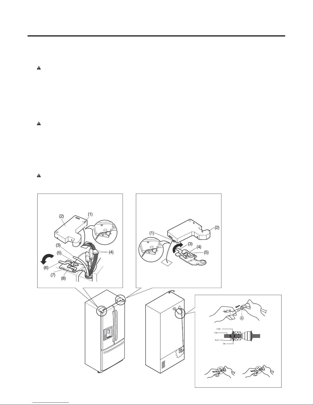
REMOVING AND REPLACING REFRIGERATOR DOORS .................................................... ................................... 6
DOOR ............................................................................................................................. ............................................ 7
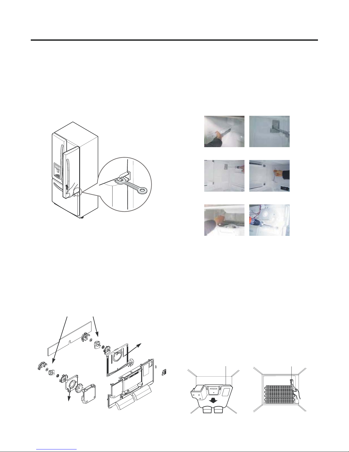
DOOR ALIGNMENT ..................................................................................................................... 7
FAN AND FAN MOTOR (EVAPORATOR) ........................................................... ....................................................... 8
DEFROST CONTROL ASSEMBLY ....................................................................... ..................................................... 8
LAMP ............................................................................................................................... ........................................... 8
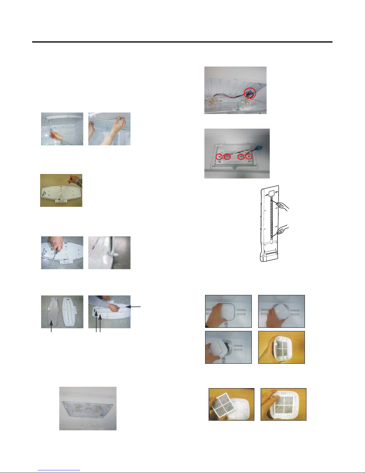
AIR FILTER ................................................................................................................ ................................................ 9
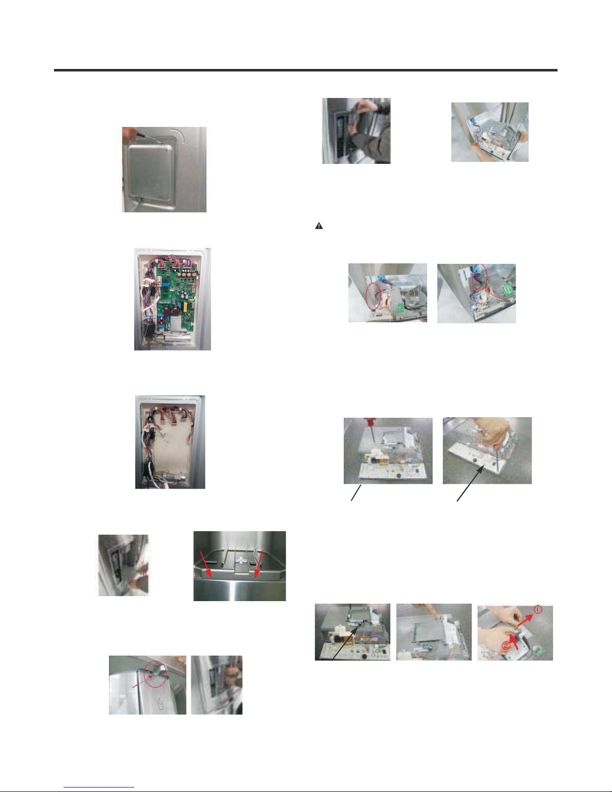
MAIN PCB ............................................................................................................. ..................................................... 9
DISPENSER ......................................................................................................... ...................................................... 9
DISPLAY PWB REPLACEMENT ........................................................................ ........................................................ 9
FUNNEL REPLACEMENT ....................................................................................... .................................................. 10
SUB PWB FOR DISPENSER .............................................................................. ....................................................... 10
CAP DUCT REPLACEMENT ............................................................................... ...................................................... 10
CAP DUCT MOTOR REPLACEMENT ................................................................. ...................................................... 10
ICE CORNER DOOR REPLACEMENT .................................................................. ................................................... 10
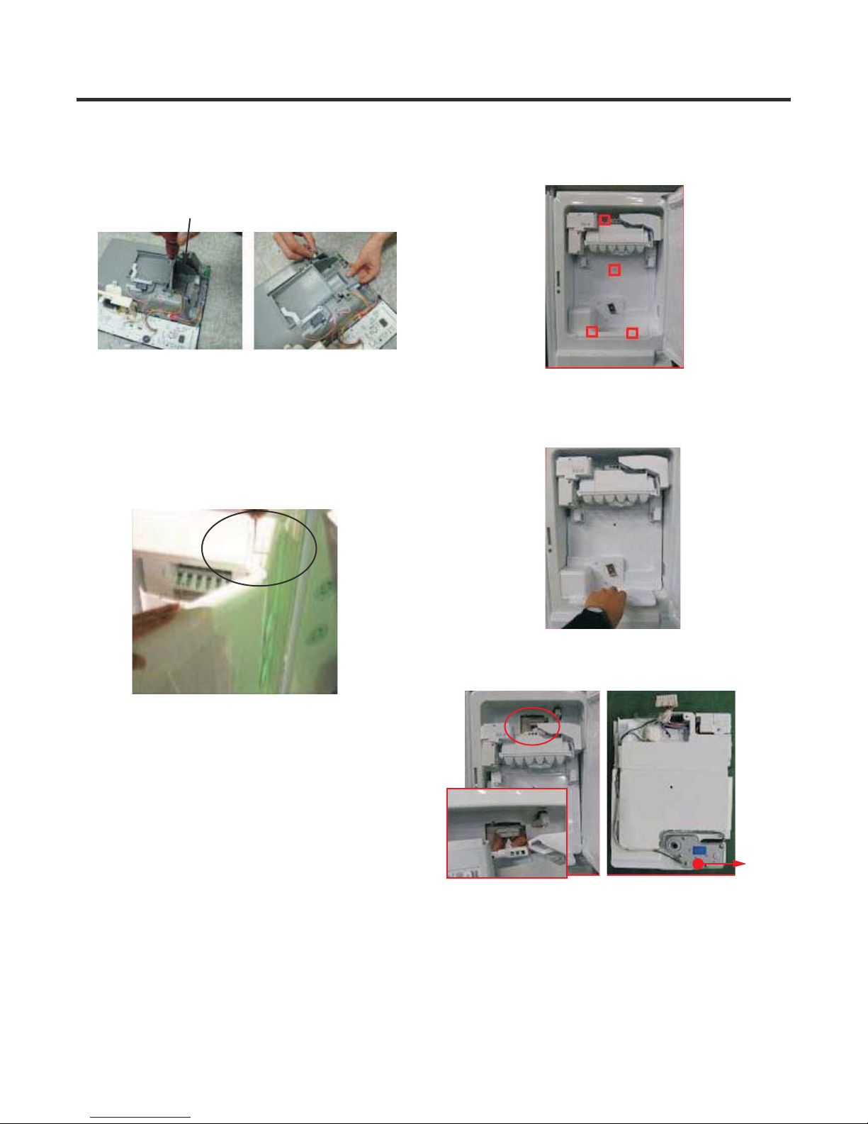
ICEMAKER REPLACEMENT ................................................................................ ..................................................... 11
HOW TO REMOVE A ICE BIN ................................................................................. .................................................. 11
HOW TO INSERT A ICE BIN .............................................................................. ........................................................ 11
HOW TO REMOVE AND REINSTALL THE PULLOUT DRAWER ................................. ............................................ 12
WATER VALVE DISASSEMBLY METHOD .................................................................. .............................................. 13
FAN AND FAN MOTOR DISASSEMBLY METHOD .............................................. ..................................................... 13
PULL OUT DRAWER .................................................................................................... ............................................. 13
4. ADJUSTMENT .......................................................................................................................... ................................... 14
5. CIRCUIT DIAGRAM ...................................................................................................... .............................................. 15
6. TROUBLESHOOTINTG ........................................................................................ ...................................................... 16
7. PCB PICTURE ......................................................................................................... .................................................... 17
8. TROUBLESHOOTING WITH ERROR DISPLAY ..................................................... ................................................... 19
9. TROUBLESHOOTING WITH ERROR DISPLAY ..................................................... ................................................... 28
10. REFERENCE ............................................................................................................................. ................................ 37
11. COMPONENT TESTING INFORMATION ................................................................... .............................................. 43
12. TRBOUBLESHOOTING .............................................................................................. .............................................. 52
13. ICEMAKER OPERATING METHOD AND TROUBLESHOOTING .......................... ................................................. 65
14. DESCRIPTION OF FUNCTION & CIRCUIT OF MICOM ............................................. ............................................. 69
15. EXPLODED VIEW .......................................................................................................... ........................................... 71
................................................
SAFETY PRECAUTIONS
Please read the following instructions before servicing your refrigerator
1 Unplug the power before handling any elctrical componets
2 Check the rated current voltage and capacity
3 Take caution not to get water near any electrical components
4 Use exact replacement parts
5 Remove any objects from the top prior to tilting the product
.
..
.,,.
..
..
..
MULTI DUCT ................................................................................................................ .............................................. 9

1. SPECIFICATIONS
Color STAINLESS WHITE BLACK
Dimensions (in)
Net Weight (lb)
Capacity
Refrigerant
Climate Class
Rated Rating
Cooling System
Temperature Control
Insulation
Compressor
Evaporator
Condenser
Lubricanting Oil
Drier
Capillary Tube
First Defrost
Defrost Cycle
Defrosting Device
Anti-freezing Heater
Water Tank
Auto ice maker
Case Material
Door material STAINLESS PCM PCM
Handle Type
Display Graphic
R-VEGETABLE
Ice Tray & Bank
Lamp
Shelf
Egg Bank
Pantry
F, Drawer lower
Lamp
Shelf
GENERAL FEATURES
ISO8 (180 ml)
MOLECULAR SIEVE XH-7
ID Ø 0.75
4 HOURS
7-50 HOURS
SHEATH HEATER
CYCLO PENTANANE
LINEAR
Defrosting System FULL AUTOMATIC
HEATER DEFROST
24.2cu.ft.
TEMPERATURE (N)
DOOR
HIGH BRIGHTNESS LED
AL SPIRAL CONDENSER
1EA PL+1EA PL
FIN TUBE TYPE
CAPSULE LED
NO
FREEZER
3FIX(S/PROOF)+1FOLD
WATER TUBE HEATER
REFRIGERATOR
R134A
2 CRISPER
EMBO
32 3/4 X 35 3/8 X 69 3/4 (WXDXH)
321lb
B-VISTA
SLIM IN DOOR AUTO ICE MAKER
115/60
FAN COOLING
YES(Digital)
MICOM CONTROL
SPECIFICATIONS
MODELS
LFXS24623S LFXS24623W LFXS24623B
NO
TWISTING
10-Majesty-Brand-Best

2. PARTS IDENTIFICATION
3
5
6
6
1
2
4
ADJUSTABLE REFRIGERATOR SHELVING
1
The refrigerator compartment shelves are adjustable to
allow flexibility for storage needs.
GALLON STORAGE BINS
2
Three interchangeable bins can be arranged to suit your
storage needs.
REMOVABLE ICE STORAGE BIN
3
The ice storage bin can be removed to fill ice buckets,
coolers, or pitchers.
LED INTERIOR LAMPS
4
Refrigerator interior is lit by the LED array.
CAN STORAGE BIN
5
FIXED DOOR BIN
6

3. DISASSEMBLY
3-1 REMOVING AND REPLACING REFRIGERATOR DOORS
Removing Refrigerator Door
CAUTION: Before you begin, unplug the refrigerator. Remove food and bins from doors.
Left Door -FIG. 2
1. Disconnect water supply tube by pushing back on the disconnect ring (3).-FIG. 1
2. Open door. Loosen top hinge cover screw (1).
Use flat tip screwdriver to pry back hooks on front underside of cover (2). Lift up cover.
3. Disconnect door switch wire harness and remove the cover.
4. Pull out the tube.
5. Disconnect all 3 wiring harnesses (4). Remove the grounding screw (5).
6. Rotate hinge lever (6) counterclockwise. Lift top hinge (7) free of hinge lever latch (8).
7. Lift door from middle hinge pin and remove door.
8. Place the door with the insides facing up, on a not scratch surface.
CAUTION: When lifting hinge free from the latch, be careful that door does not fall forward.
Right Door -FIG. 3
1. Open the door, remove 1 screw on the top of the hinge cover. Loosen top hinge cover screw (1). Lift up cover (2).
2. Disconnect door switch wire harness and remove the cover.
3. Rotate hinge lever (3) clockwise. Lift top hinge (4) free of hinge lever latch (5).
4. Lift door from middle hinge pin and remove door.
5. Place the door with the insides facing up, on a not scratch surface.
CAUTION: When lifting hinge free from the latch, be careful that the door does not fall forward.
Figure 2 Figure 3
Figure 1
1) Insert the tube until you can see only one of
the lines printed on the tube.
2) After inserting, pull the tube to ascertain that
it is secure.
3) Assemble clip.

1. Remove gasket
Pull gasket free from gasket channel on the four
remaining sides of door.
3-2 DOOR
Mullion Removal
1. Remove 2 screws.
Door Gasket Removal
2. Lift Mullion up carefully.
3. Disconnect wire harness.
Door Gasket Replacement
1. Insert gasket into channel
Press gasket into channels on the four remaining
sides of door.
2. Insert mullion into the channel.
Insert the cover assembly into bracket, door.
Mullion Replacement
1. Connect wire harness.
3. Assemble 2 screws.
Figure 1
Figure 2
Figure 3
Figure 4
Figure 5
Figure 6
Figure 7
Figure 8

* Ice Fan Scroll Assembly Replacement
1) Remove the plastic guide on the left side, using a
phillips screwdriver to remove the screws.
2) Pull off the sensor cover.
3) Remove the grill cover.
4) Gently pull on the grill assembly to remove.
5) Disconnect the wiring harness.
6) Remove all screws on the scroll assembly.
(1) (2)
(3) (4)
(5) (6)
3-5 DEFROST CONTROL ASSEMBLY
Defrost Control assembly consists of Defrost Sensor and
FUSE-M.
The Defrost Sensor works to defrost automatically. It is
attached to the metal side of the Evaporator and senses its
temperature. At 46F(8°C), it turns the Defrost Heater off.
Fuse-M is a safety device for preventing over-heating of
the Heater when defrosting.
1. Pull out the grille assembly. (Figure 12)
2. Separate the connector with the Defrost Control
assembly and replace the Defrost Control assembly after
cutting the Tie Wrap. (Figure 13)
Figure 12 Figure 13
GRILLE ASSEMBLY DEFROST-CONTROL
ASSEMBLY
3-3 Door Alignment
If the space between the door are uneven,
follow the instructions to align them.
Remove the Base Grillie. Turn the leveling legs counter
clock wise to raise or clock wise to lower the height of the
front of the refrigerator by using flat blade screw driver or
11/32" wrench. Use the wrench (Included with the User
Manual) to adjust the bolt in the door hinge to adjust the
height. (CCW to raise or CW to lower the height.)
3-4 FAN AND FAN MOTOR(EVAPORATOR)
1. Remove the freezer drawer. (If your refrigerator has an
icemaker, remove the icemaker first)
2. Remove the plastic guide for slides on left side by
unscrewing phillips head screws.
3. Remove the grille by removing 4 screws and pulling the
grille forward.
4. Remove the Fan Motor assembly by loosening 3 screws
and disassembling the shroud.
5. Pull out the fan and separate the Fan Motor and Bracket.
FAN MOTOR
BRACKET
MOTOR
Shroud
Figure 9
Figure 10
Figure 11

1. Unplug refrigerator power cord form outlet.
2. Remove screw with driver.
3. Grasp the cover Lamp, pull the cover downward.
3-6-2 Freezer Compartment Lamp
3-7 MULTI DUCT
1. Remove the upper and
lower caps with a flat
screwdriver and remove
2 screws.
(Figure 19)
2. Disconnect the lead wire
on the bottom position.
Figure 14
Figure 15
3-6 LAMP
Unplug, or disconnect power at the circuit breaker.
If necessary, remove top shelf or shelves.
1) Release 2 screws.
2) Hold both ends and pull down to remove.
3-6-1 Refrigerator Compartment Lamp
Figure 16
4) Use a flat tool as shown below to remove the lamp
cover.
Figure 17
5) To remove the LED assembly, pull apart the cover.
Cover, lamp
Case, lamp
LED, Assembly
3) To remove the lamp case and cover, release 2 screws
as shown.
4. Separate connector.
5. Remove screw with driver.
1. Remove filter cover to turn counterclockwise about
30 degree.
3. Filter cover put on multi duct in position, and turn air filter
clockwise about 30 degree.
2. Remove old air filter from filter cover. Install new
air filter in filter cover to see “FRONT”.
3-8 AIR FILTER

3-9 MAIN PCB
1) Loosen 3 screws on the PWB cover.
3-10 DISPENSER
1) Pull out the drain
2) Remove the PCB cover
3) Disconnect wire harness and replace the main PCB in
the reverse order of removal.
3-11 DISPLAY PCB
As shown below, remove 1 screw on the PCB fixing screw.
Remove the display PCB fixing screw.
3-12 ICE BUTTON ASSEMBLY
1) Remove the 1 screw holding the lever.
2) Remove the spring from the hook.
3) Push and pull on the tab to remove.
CAUTION: When replacing the dispenser cover make
sure the lead wire does NOT come off and the water line
is not pinched by the dispenser.
Case, PCB
Button Lever
Display PCB
Figure 20
Figure 21
Figure 22
Figure 23 Figure 24
Figure 25
Figure 30
Figure 28
Case, PCB Display PCB
Figure 29
Figure 28
2) Use these 2 holes to pull
out the bottom
3) If nozzle is interfered with button, push and pull out the
bottom of button and then pull out the right side.
4) Holding the inner side of
the dispenser pull
forward to remove.
5) Remove the
lead wire.
Figure 26 Figure 27

3-14 ICE CORNER DOOR REPLACEMENT
1) Loosen the front screw as shown in the picture.
2) Lift up the hinge with one hand.
3) Pull out the Ice Corner Door with the other hand.
3-13 WATER BUTTON ASSMEBLY
1) Remove screws.
2) Grasp the Button assembly and lift.
Button Lever
hinge
1) Remove 4 screws as shown.
3-15 ICEMAKER REPLACEMENT
2) Grasp the bottom of motor cover assembly and pull
slowly.
3) Disconnect wire harness from wall of compartment.
In-door
motor
Figure 31
Figure 32
Figure 35
Figure 33
Figure 34

3-17 CAP DUCT MOTOR REPLACEMENT
1) Separate the Housing of the Cap Duct Motor.
3) When replacing the motor, check the position of the door
duct and the link for proper fit.
Link
Duct Door
Cap Duct Motor
NG Position
2) Unscrew 3 screws to disassemble the motor.
4) Insert 2 screws.
5) Push housing aside.
3-16 SUB PWB FOR WORKING DISPENSER
1) Disconnect the wire harness.
2) Remove 1 screw from PWB and replace with new PWB.
CAUTION: Make sure that the motor housing is taped to
the mold, if not positioned correctly the cover will not fit
properly.
Figure 36
Figure 37
Figure 38
Figure 43
Figure 42
Figure 41
Figure 40
Figure 39

3-18 HOW TO REMOVE A ICE BIN
1) Grip the handles, as shown.
2) Tilt and lift slightly as shown.
3-19 HOW TO INSERT A ICE BIN
1) Insert the Ice Bin, slightly tilting to avoid touching the
Icemaker. (Especially, Ice-Detecting Sensor)
3) Remove ice bin slowly.
Figure 44
Figure 45
Figure 46
Figure 47

3-20 HOW TO REMOVE AND REINSTALL THE PULLOUT DRAWER
3-20-1 Follow Steps to Remove
Step 1) Open the freezer door. Step 2) Remove the lower basket.
Step 3) Remove 2 screws one on each side of the guide
rails.
Step 4) Removal of the freezer door is done by lifting clear
of the rail support. Fully extend both rails.
Step 5) First: Remove the gear from the left side first by releasing the tab behind the gear, place a screwdriver between the
gear and the tab and pull up on the gear.
Second: Remove the center rail.
Third: Remove the gear from the right side by following the same steps for the left side.
NOTE: THIS TAB MUST BE PUSHED IN TO RELEASE THE GEAR.
Figure 48 Figure 49
Figure 51Figure 50
Figure 52

3-20-2 Follow Steps to Reinstall
Step 1) Reinstall the right side of the gear into the clip.
Step 2) Insert the rail into the right side of the gear. Gears
do not need to be perpendicular to each other.
Step 3) Insert the rail into the left side of the gear, and
insert the gear into the clip.
Step 4) The rail system will align itself by pushing the rails
all the way into the freezer section.
Pull the rails back out to full extension.
Step 5) Reinstall the freezer door by inserting the rail tabs
into the guide rail.
Step 6) Reinstall 2 screws into the guide rail one on each
side.
Step 7) Reinstall the lower basket, and close the freezer
door.
Figure 53
Figure 55Figure 54
Figure 56 Figure 57
Figure 59Figure 58

3-21 WATER VALVE DISASSEMBLY METHOD
1) Turn off the water to unit. Remove the waterline from the
valve.
3-22 FAN AND FAN MOTOR DISASSEMBLY
METHOD
1) Remove screws for the Drain Pipe Assembly and the 1
connected to the Motor Cover.
2) Remove cover and 1 screw from the valve.
3) Separate the housing and remove the valve.
4) Remove the clip, and press the collet to separate the
tube from the connector. Note: there maybe some water
in the line.
Mechanical Cover
Housing
MOTOR COVER
2) Separate the Fan Assembly and Motor, turn counter
clockwise to remove from the motor shaft.
FAN ASSEMBLY MOTOR
Assemble in reverse order. Taking care to avoid.
1. Do not to bend the tube during assembly.
2. Press the Water Dispenser button letting water pour out,
this checks for any leaks in the tube connection, this may
vary depending on the water pressure
( about 2 minutes.).
Figure 60
Figure 61
Figure 62
Figure 63
Figure 64
Figure 65

3-23 Drawer Removal
Fully extend the drawer and lift from the front pulling straight out.
To install the drawer back into the frame, tilt the front sightly and pushingt back into place.
Figure 66
Figure 67

4. ADJUSTMENT
4-2 INTRODUCTION OF E-LINEAR COMRESSOR
E-Linear compressor is run by mechanical part design
through automatically varying the cooling power. The
main parts consist of compressor and Sub PCB which
controls the compressor. PCB authorizes constant
voltage and constant frequency to the compressor and
protects it.
Drive half stroke after turning on initial power for 30
seconds. Then, slowly increase stroke and reach target
input. Once reaching the target input, input naturally
changes according to refrigerator load without any special
control.
Interval 1) Half stroke interval - after initial running, stay at
the initial value for 30 seconds
Interval 2) Running interval - Increase at every 0.8 till it
reaches the target input; it takes about 3’ 45”
Interval 3) CVCF interval - Run by target voltage and main
operating frequency and the input naturally
changes according to refrigerator load
4-1-1 Role
4-1 COMPRESSOR
The compressor intakes low temperature and low pressure
gas from the evaporator of the refrigerator and compresses
this gas to high-temperature and high-pressure gas. It then
delivers the gas to the condenser.
4-1-2 Note for Usage
(1) Be careful not to allow over-voltage and over-current.
(2) Do not drop or handle carelessly.
(3) Keep away from any liquid.
If liquid such as oil or water enters the Cover PTC
Compressor may fail due to breakdown of their
insulating capabilities.
(4) Always use the Parts designed for the compressor and
make sure it is properly attached to the compressor.
Parts may appear physically identical but could have
different electrical ratings. Replace parts by part number
and model number. Use only approved substitute parts.
4-1-3 Remove the cover PTC
(1) Remove the Cover Back M/C
(2) Loosen two screws on comp base
(3) Use a L-shaped flap tooll to pry off the cover
(4) Assembly in reverse order of disassembly
4-2-1 Control of Compressor Block Diagram
4-2-2 Compressor operating pattern
Compressor Controller Inverter
PWM
Signal
Frequ
-ency
Linear
Comp
DC link
Voltage
Main
Micom
Calculate counter
electromotive force
Counter elec-
tromotive force
Vcap Voltage
Control Block Diagram of Compressor
Comp. input

Multi-tester
4-2-4 Compressor problems diagnosis
When there is a problem or failure with the `operation,
you are kindly recommended to check it as follows ;
Measure the resistance between poles of the hermetic
terminal (as shown picture) with a multi-tester.
(measurement several minutes after power off)
Normal resistance range (measured at ambient
temperature 23 )
Case 1-1
If the measured values lie in the normal resistance range as
in the table below,
Compressor is normal.
Case 1-2
If the measured values are above several M or a infinity,
Wire is disconnected in the shell.
Case 1-3
If the measured values are excessively of small number,
There is short somewhere in the shell.
1) Check to normality by measurement of resistance
According to ambient temperature or operation situation,
the values could show a little deviation.
4-2-3 Compressor protection logic
Since linear Comp conducts linear reciprocating motion,
we have protection logic for compressor, motor and PCB
as the below.
- Stroke Trip
During the operation, if stroke is above the target value,
decrease the target volt by 3V.
- Current Trip
Current trip is set in order to protect compressor
mechanical part and drive from the overcurrent that might
arise during the operation.
Check the current for every 416.7us and if the Trip
exceeds 1.86Arms more than three times at Comp ON,
forcibly stop and restart six minutes later.
- Lock Piston Trip
If stroke is under 5mm even if the current is more than
14Arms, Take it as ‘piston lock’ and restart after 2’30” of
Comp OFF. Check the current and stroke for every
416.7us and if the condition fits more than three times at
Comp ON, the Trip occurs.
- IPM fault Trip
It occurs if FO signal received from IPM is LOW. For
every 416.7us, check whether FO signal is LOW. The trip
occurs if it is found three times during the five
periods(83ms).
P : Power Line
C : Common Line
Resistance
7.2~9.2 ΩFLB075L*NA

Measure the resistance between pin of the connector (as
shown picture) with a multi-tester.
Standard for normality
- In order to decide whether compressor operating is normal
or not, check the output transfer during the refrigerator
operation.
- After input the initial power and compressor operates, wait
for 10 minutes to estimate.
- Compressor operation may be diagnosed as normal if the
voltage falls between 145V and 180V.
Warning
1. Please be cautious of electric shock and short (it is
estimated after turning on initial power).
2. If the voltage is estimated less than 80V, it is diagnosed
as bad.
2) Check to normality by measurement of Voltage
If compressor protection logic is running, LED Lamp’s
blinking frequency of sub PCB, which takes in charge of
control, can help estimate the protection logic’s symptoms
and the cause of its problems.
Trip name
Stroke Trip
Current Trip
Lock Piston Trip
IPM fault trip
Led Times
2
6
5
7
Comp Off Time
1min
6min
2min 30sec
20sec
3) Check problems by LED On & Off Count _ (Sub PCB)
<Fig. 2> <Fig. 2>
- Current Trip PCB defects or Cycle clogging maybe the
causes. After estimating winding resistance, estimate
compressor operation voltage to check if there is any
problem and take actions to repair cycle at replacement of
compressor.
-StrokeTrip can occur when the surrounding
temperature is high, C-Fan, F-Fan and so on are
constrained, or when cycle problems, such as moisture
blocking or compressor defect, are related.
- Lock Piston Trip Since compressor itself can be a
potential cause of a defect, estimate the compressor
resistance value according to #1’s compressor winding
value estimation method and estimate the #2’s
compressor operation voltage to decide whether it is
defective or not
(Before replacement of compressor, replace PCB and
conduct the replacement of compressor during
compressor replacement)
- IPM fault Trip Replace sub PCB since there is high
chance that it is caused by sub PCB’s part defect.

5. CIRCUIT DIAGRAM
This manual suits for next models
2
Table of contents
Other LG Refrigerator manuals