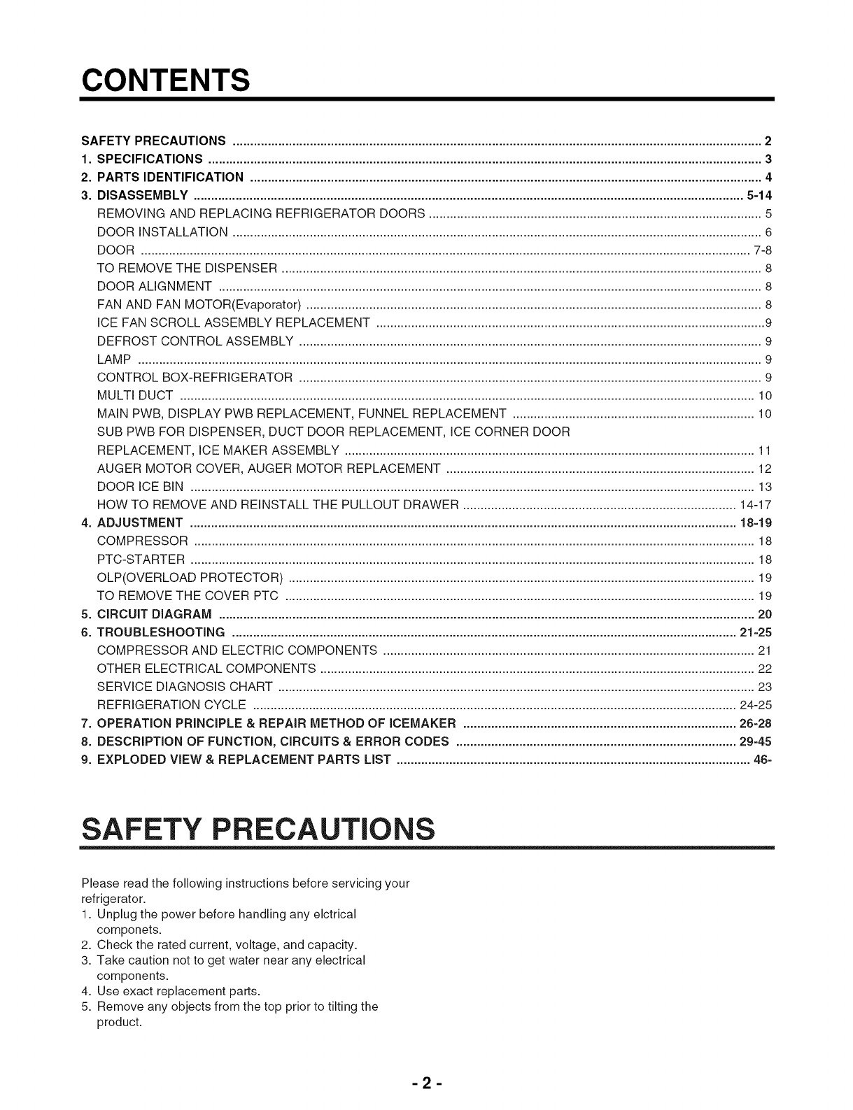
CONTENTS
SAFETY
PRECAUTIONS.
........ecescescceseeeeeeseeeeeeseeseeseeeseesceesaesenescessnesseesnenseeseeeaenenaeaenenanaeenensaesnessansseesaeeseesaeesesaeeneeeenteseneesenenes
2
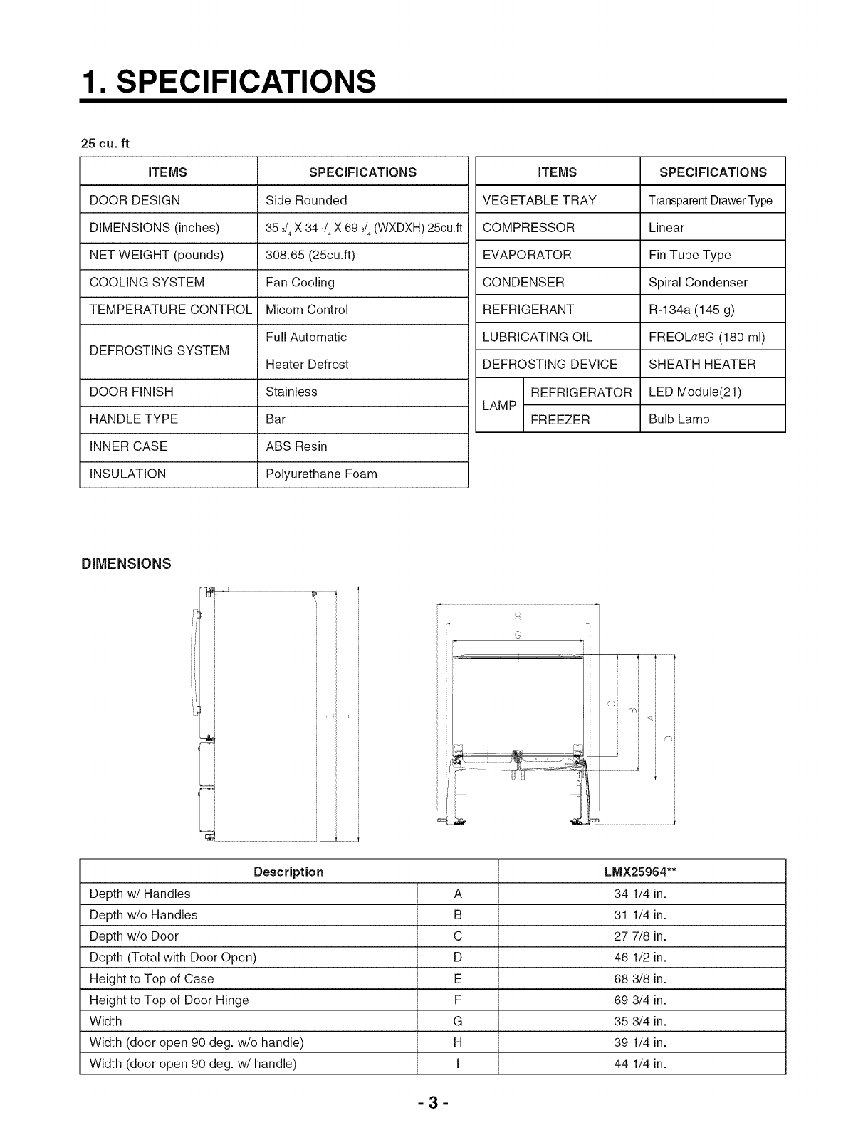
1.
SPECIFICATIONS.
ooo.
.s
cee
ceececeeecesceeeeeeceeeces
ce
enenseeenensensncenenenaesenenensaneneesaesaessanssensaeesessaessess
cesses
sesaeesaeeeaesaseneeeeseneneeneneneneeaes
3
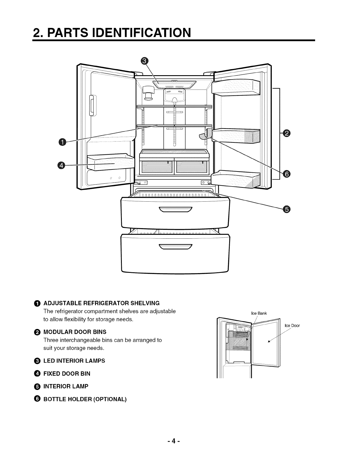
2.
PARTS
IDENTIFICATION
..........ccceccesceecceeeeeeceeeeeeeeeee
cane
eee
nanenae nse
esnen
snes
neues
eens
eee
eens
ee
nee
nena
eae
nen
enna
enna
4
3.
DISASSEMBLY
00...
ceseecccecceeceeseeeeeeeeeeeceseeeecenenenenneeeaeesaecaeesaesaasaesaaesaeseeegaesaese
sess
ceases
seeeeeaeeeeesaeesaesaesaesnaeseenseneeeseaees
5-14
REMOVING
AND
REPLACING
REFRIGERATOR
DOORS
0000...
ceccceccceccecceeceeseeeeeceeeeeecaeeeeecaeecaecaaecaeeaaeaeeaesareneenseneeeneenes
5
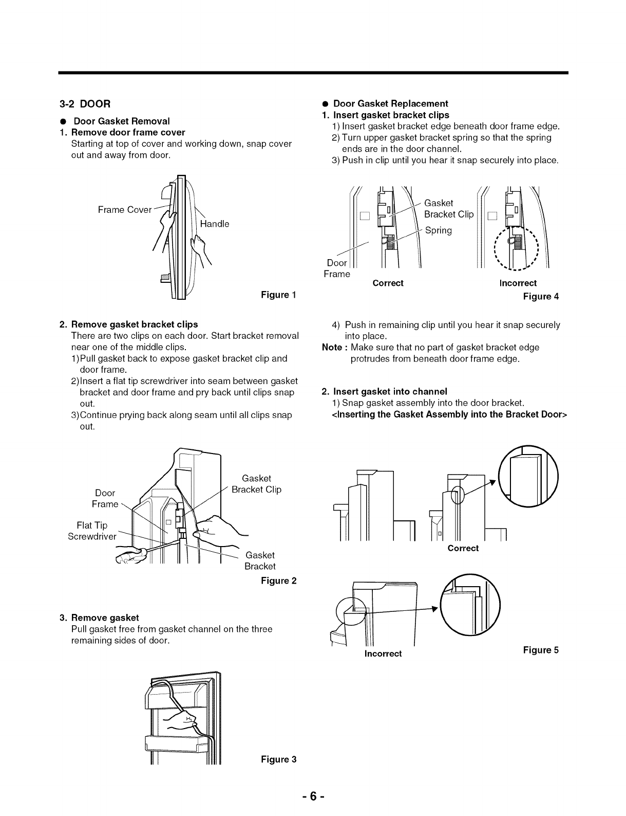
DOOR
INSTALLATION
ooo...
ccccccccecceececseeececaceseeceeeeaecaeceaecaecsaecaecsaeceeseaeceneseesenesececaeeeaecacecaecaaecaeseaesaesaseaeesaesaresaeeeeseseseneeaeeenes
6
DOOR
oo
ceececcceccecccecceseceeceseceecesecenesessaecsnecaeeeaecacecaecaaecaecaaecaecsassaeceaeaessaeseeseaeseeseaeseneseeeaecaeecaeeececaeesaesaeeeeecaseeeseseetenseeteaes
7-8
TO
REMOVE
THE
DISPENSER
20.
.ecccceccceccecccececeeeeneeeeeceeeacecaceaaecacesaecaaeeaeceaesaeceaeaecaeseaesieeeaesecesneeaeseeesaeeeeesaeeeeeieeseeeeaees
8
DOOR
ALIGNMENT
ooo..ececcceccecceescesceceeeececacesnecacesaecaeceaecaecsaecaecsaecaesaecenesaesecesenecaeeeaecacecaecaaecaeseaesaeceaeeaeenesareeaeseeeeenseneeaeeenes
8
FAN
AND
FAN
MOTOR(Evaporat0r)
........ccccsccccssccceesercesenseccsenceceaececsnaececeneeccaaececenaeceseneececassecsensesseasecscassecsenssessureescuteeesanes
8
ICE
FAN
SCROLL
ASSEMBLY
REPLACEMENT
ooo...
.eccceccccccescececeseeeeeeaeecaeeacecaecaaecaeeeaecaeeaecaeeeaeseeeaeseeeseeteneseeeeeeeeeieenaees
9
DEFROST
CONTROL
ASSEMBLY
o....eccccceceescceceecceeececeeeceseeseceaecsesesecneceeeeaecacecaecacecaeeaaecaaesaeseacsaeceaeeaeceeesaeseeeeeseseeeeeeaeeeees
9
LAMP
ooeeeececcecccecceeccesceseeeceseceeesesenecseecaeececacecaecacecaecaaesaecsaesaeseaesaessaesaesaeseeeaesenesaeecaecacecaeeacecaesaaecaesaecaecsaeseeesaeeneeeeseneeeeeenes
9
CONTROL
BOX-REFRIGERATOR
oo.
.cccceccceccesceececececeecececaecaaeceeceaecaecaaecaecaaesaesaesnesaeseneseesaeeececaeesaeseaeeaeseaeeeessuseareneeereaes
9
MULT
DUCT
oe
cececceccecceecceeceeceeceseeeeeeaeeaecace
caeeacecaceaaecacesaecaeceaeceecsaecaesaecaeseaeseeesaeseneseeseneseecaeeecesaeesaeceeesaeseaseeesseereeteas
10
MAIN
PWB,
DISPLAY
PWB
REPLACEMENT,
FUNNEL
REPLACEMENT.
...........:cccccececceeeeceeeceeceeeceeceeeeeseaeeereeareneeeneaes
10
SUB
PWB
FOR
DISPENSER,
DUCT
DOOR
REPLACEMENT,
ICE
CORNER
DOOR
REPLACEMENT,
ICE
MAKER
ASSEMBLY
o.uu....cccecccecceecceccecces
cesses
cesses
eeseceneeeeeeaeceecaeeeaesacecaecacecaeseaesaeeeaseeesiseereseneereeas
11
AUGER
MOTOR
COVER,
AUGER
MOTOR
REPLACEMENT
ou......ecccecccccecceeeceseececeeeeceeceeecaecaeceeseaecaeeeaeseseseeteneseneeaeeeees
12
DOOR
ICE
BIN
0
eeccecccecceeceecceseeecceneeeneeaeeeeecace
caeeacecaceaaecaecaaecaecsaecaecsaecaessaecaeseaeseeeaeseneeeeseneseecaesacecaeesaeceeeeaeseaseeeeuseereeteas
13
HOW
TO
REMOVE
AND
REINSTALL
THE
PULLOUT
DRAWER
...0.....ccccceccececececeececeeeececeeeeceaeeaeceeeaeeeeseeseneeareeseeees
14-17
A.
ADJUSTMENT
nnn.
.eceeececeeeccesesseeeeeeenencesececesncencesecensesecenaeenaeaaecaesaaecaesaaecaessaesaessaessessaessessseeseeseesesesaeenaeeesenaeeeseneseaeenes
18-19
COMPRESSOR
oooeececccecceceesececceeeeeceeeceeecaeceaeeseceaeceecenesenesaesenecaeeeaecace
caeeaaecaaesaecaeceaesaecaeseeseaeceeseaeseeeeeseeesereeaeseeesaeeeeeieeeaees
18
PTC-STARTER
.ecccceccceccesceecceseeeeceneeeneeaeeenecace
caecacecaeeaaecaecaaecaeceaeceecsaecaesaecaesaeseeeaeseneceseneseesaesacesaeesaececeaeseaseeeeeseeseeteas
18
OLP(OVERLOAD
PROTECTOR)
.0....cccccccecccceceeeececceecceeeaeceeceseceeeeseceneceneeaeeenecaeecaecacecaecaaecaeeaaecaeseaesaeseaseaeseaesenseeseneeneeenes
19
TO
REMOVE
THE
COVER
PTC
oui.
.eccccccccccescceceeseeecececescecacesaeceaesaeceaeseeceaeaessaeeaeseeecaeseceseneeaeeenecacesaeeaaecaesaaesiseseeeareeeeeeeeas
19
5.
CIRCUIT
DIAGRAM
oan...
ceececceccceccescneeceeecencesecseceseeenceseeeneeseecneeenecaaeene
seas
cae
eaansaesaansaessaesaessaessaseaseseseeseseseaseneseaaeeeaeaeeaeeaes
20
6.
TROUBLESHOOTING.
ooo...
ceeceecceccescceeceeecencesncenceseceneeseecnaeeaecaeecaesaaecaesaaecaesaaesaessaes
sess
aes
sess
seeseeesaeseseaseeeaeaaeeeaeeaseneseaeeaes
21-25
COMPRESSOR
AND
ELECTRIC
COMPONENTS.
0...
ceccecececeecececeeeececeeeeceeceaeceeceaecaeceaeseeeaeceneseseaesececaeeeaesaeesaesaeeeeenaees
21
OTHER
ELECTRICAL
COMPONENTS.
......ccececcecccecceecceecesecesceseceeeeseeeneceeeeneeecaeecaecacecaecaaecaeeaaesaeceaecaeeeaseaesesesenseseseneeaeenes
22
SERVICE
DIAGNOSIS
CHART
o.oo.
.ecceccecccecceecceeeeeeeeceeececeeeece
cae
caecacecaecaaecaecaaecaeceaesaecaaesaeseaesaeseaeseeeeseseeesaeesaeseeseeseeeieenaees
23
REFRIGERATION
CYCLE
oon.
cecceeccccccecececececeeceeececeeaecaeceaecaeceaecaecsaeceeseaesenesaeseneseecaesececaeeeaecacecaeseaeaeseaseseeeseeresunestees
24-25
7.
OPERATION
PRINCIPLE
&
REPAIR
METHOD
OF
ICEMAKER
............eecccsceecceeeeeecenceeeceneeeeceneeenenseeseeeeaesenseanenenaes
26-28
8.
DESCRIPTION
OF
FUNCTION,
CIRCUITS
&
ERROR
CODES
ooo.
..ececceccesceeeceeeeeeceseeeeceneeeneeneeeneesae
ceases
seaseanenaneaes
29-45
9.
EXPLODED
VIEW
&
REPLACEMENT
PARTS
LIST
oon...
see
ceeececceeececeeeeceneeeneneeseeenceseeseceseeseeeseeenaeseecnaeeaeseeesanseneeaeeans
46-
SAFETY
PRECAUTIONS
Please
read
the
following
instructions
before
servicing
your
refrigerator.
1.
2.
3.
Unplug
the
power
before
handling
any
electrical
componets.
Check
the
rated
current,
voltage,
and
capacity.
Take
caution
not
to
get
water
near
any
electrical
components.
.
Use
exact
replacement
parts.
.
Remove
any
objects
from
the
top
prior
to
tilting
the
product.