wwWARNING
Personal Injury Hazard
Avoid contact with the moving parts of the ejector
mechanism, or with the heating element that releases
the cubes. DO NOT place fingers or hands on the
automatic icemaking mechanism while the refrigerator
is plugged in.
3-2. Operation instructions
A newly-installed refrigerator may take up to 24 hours
to begin making ice.
The icemaker will produce eight cubes per
cycle—approximately 120–150 cubes in a 24-hour period,
depending on freezer compartment temperature, room
temperature, number of door openings and other operating
conditions.
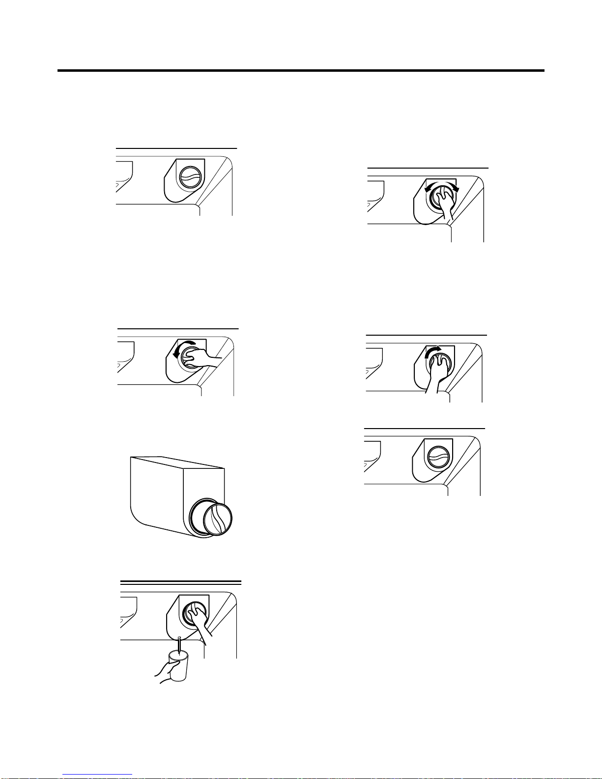
If the refrigerator is used before the water connection is
made to the icemaker, set the power switch to O (off).
When the refrigerator has been connected to the water
supply, set the power switch to I (on).
The icemaker will fill with water when it cools to freezing. A
newly-installed refrigerator may take up to 24 hours to
begin making ice cubes.
Throw away the first few batches of ice to allow the water
line to clear.
Be sure nothing interferes with the sweep of the feeler arm.
When the bin fills to the level of the feeler arm, the
icemaker will stop producing ice.
It is normal for several cubes to be stuck together.
If ice is not used frequently, old ice cubes will become
cloudy, taste stale, and shrink.
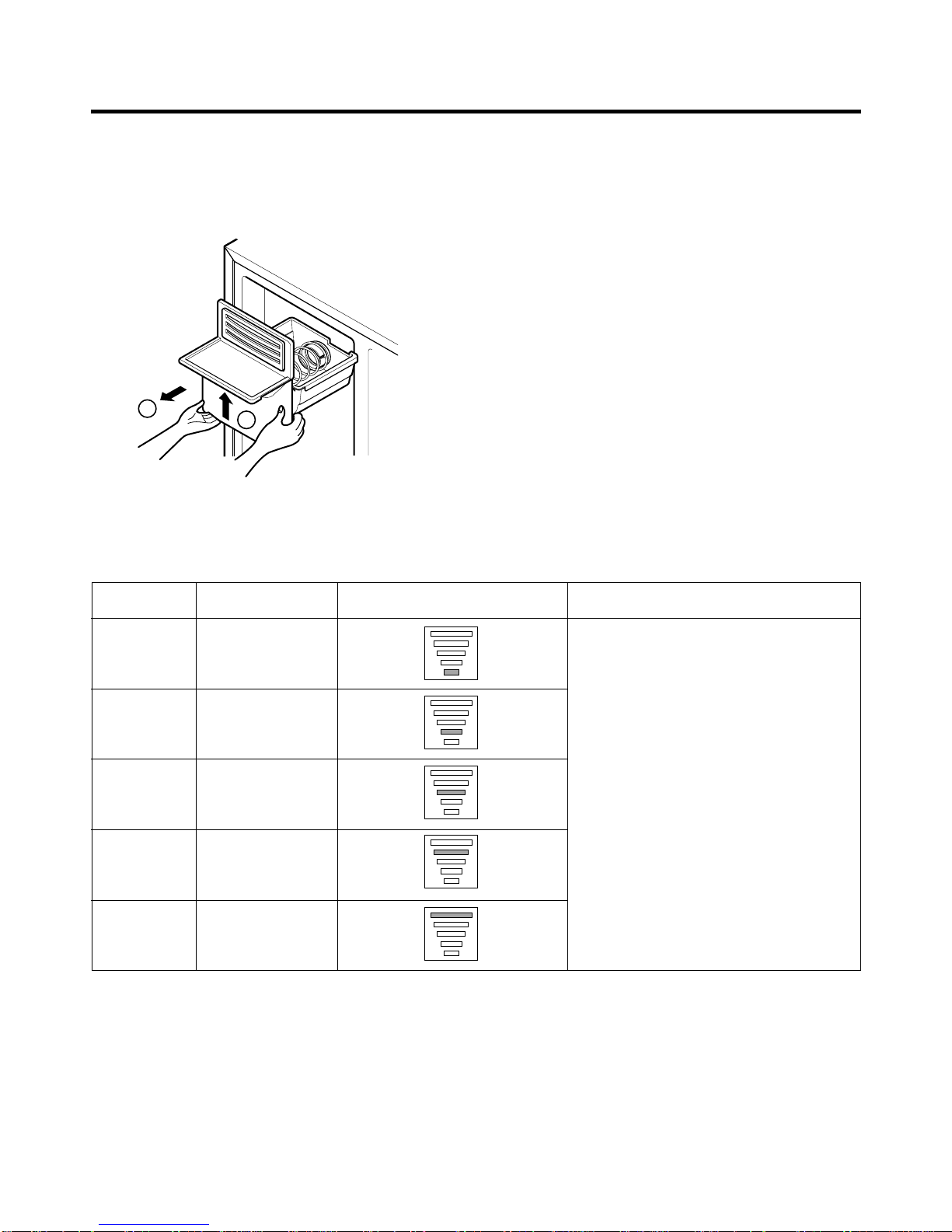
NOTE: If the cube size is smaller or larger than you
expected, you can regulate the size with the cube size
button. (nomally caused by variations in water pressure.)
Every time you press the cube size button, the indicator
light go up. The higher position light is on, the larger cubes
will be. (1st step is the next after the 5th step.)
3-3. When you should set the icemaker power
switch to O (off)
•When the water supply will be shut off for several hours.
•When the ice storage bin is removed for more than a
minute or two.
•When the refrigerator will not be used for several days.
3-4. Normal sounds you may hear
•The icemaker water valve will buzz as the icemaker fills
with water. If the power switch is in the I (on) position, it
will buzz even if it has not yet been hooked up to water.
To stop the buzzing, move the power switch to O (off).
NOTE: Keeping the power switch in the I (on) position
before the water line is connected can damage the
icemaker.
•You will hear the sound of cubes dropping into the bin
and water running in the pipes as the icemaker refills.
3-5. Preparing for Vacation
Set the icemaker power switch to O (off) and shut off the
water supply to the refrigerator.
If the ambient temperature will drop below freezing, have a
qualified servicer drain the water supply system (on some
models) to prevent serious property damage due to
flooding from ruptured water lines or connections.
HOW TO INSTALL REFRIGERATOR
- 15 -
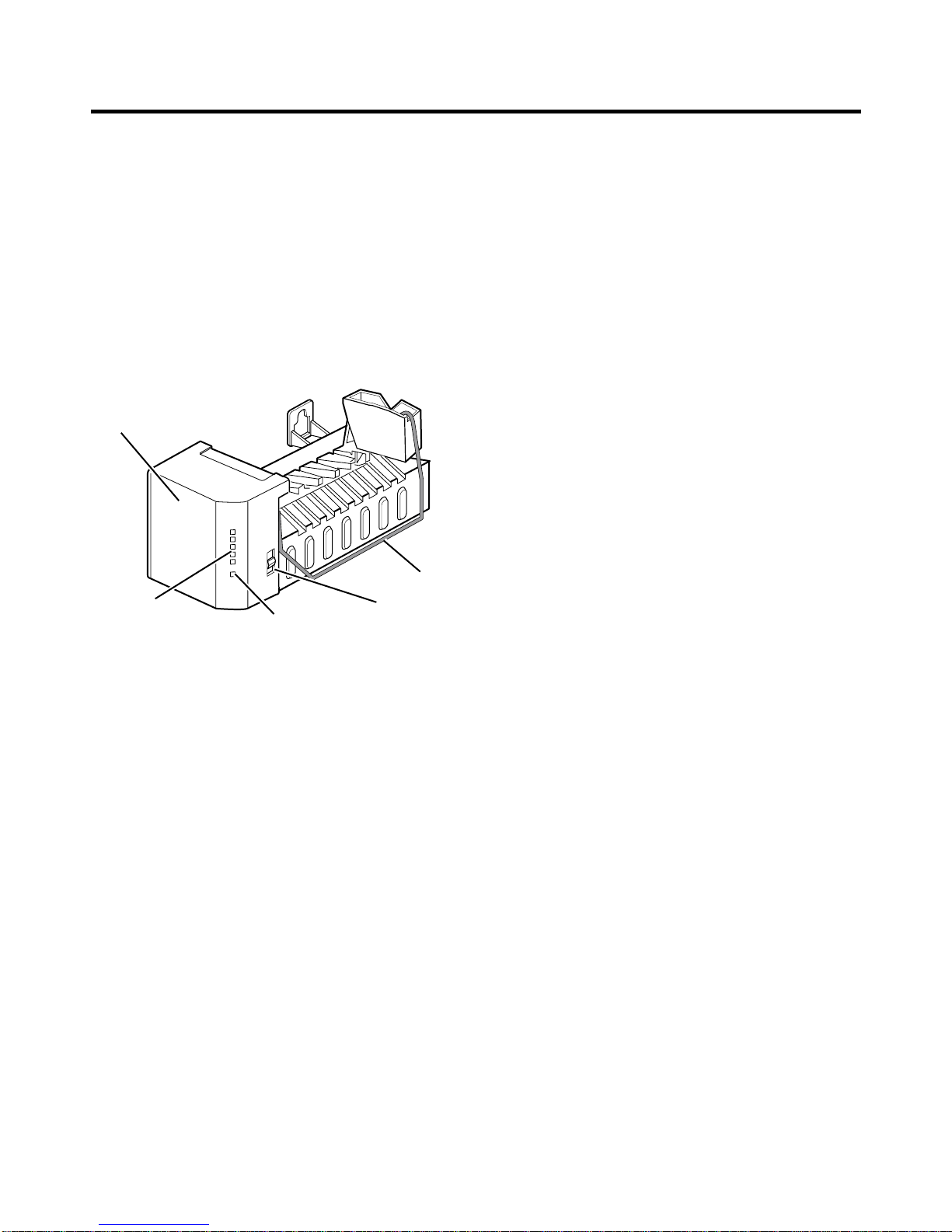
Feeler Arm
Icemaker
Cube Size
Indicator Light Water Supply
Control Switch
Power Switch