CONTENTS
SAFETY PRECAUTIONS
Please read the following instructions before
servicing your refrigerator.
1. Check the refrigerator for current leakage.
2. To prevent electric shock, unplug before
servicing.
3. Always check line voltage and amperage.
4. Use standard electrical components.
5. Don't touch metal products in the freezer with
wet hands. This may cause frost bite.
6. Prevent water from spiling on to electric
elements or the machine parts.
7. Before tilting the refrigerator, remove all
materials from on or in the refrigerator.
8. When servicing the evaporator, wear gloves to
prevent injuries from the sharp evaporator fins.
9. Service on the refrigerator should be performed
by a qualified technician. Sealed system repair
must be performed by a CFC certified technician.
.
WARNINGS AND SAFETY PRECAUTIONS
1. SPECIFICATIONS
2. PARTS IDENTIFICATION
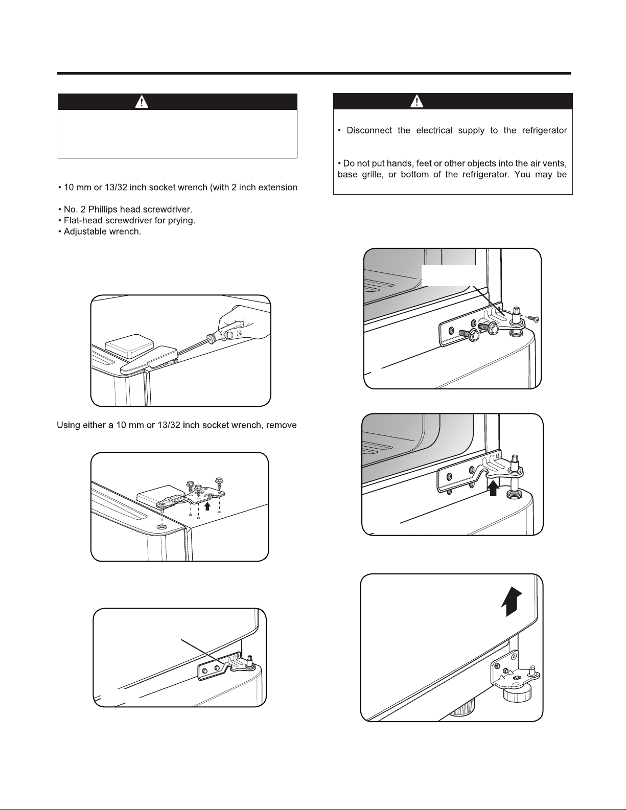
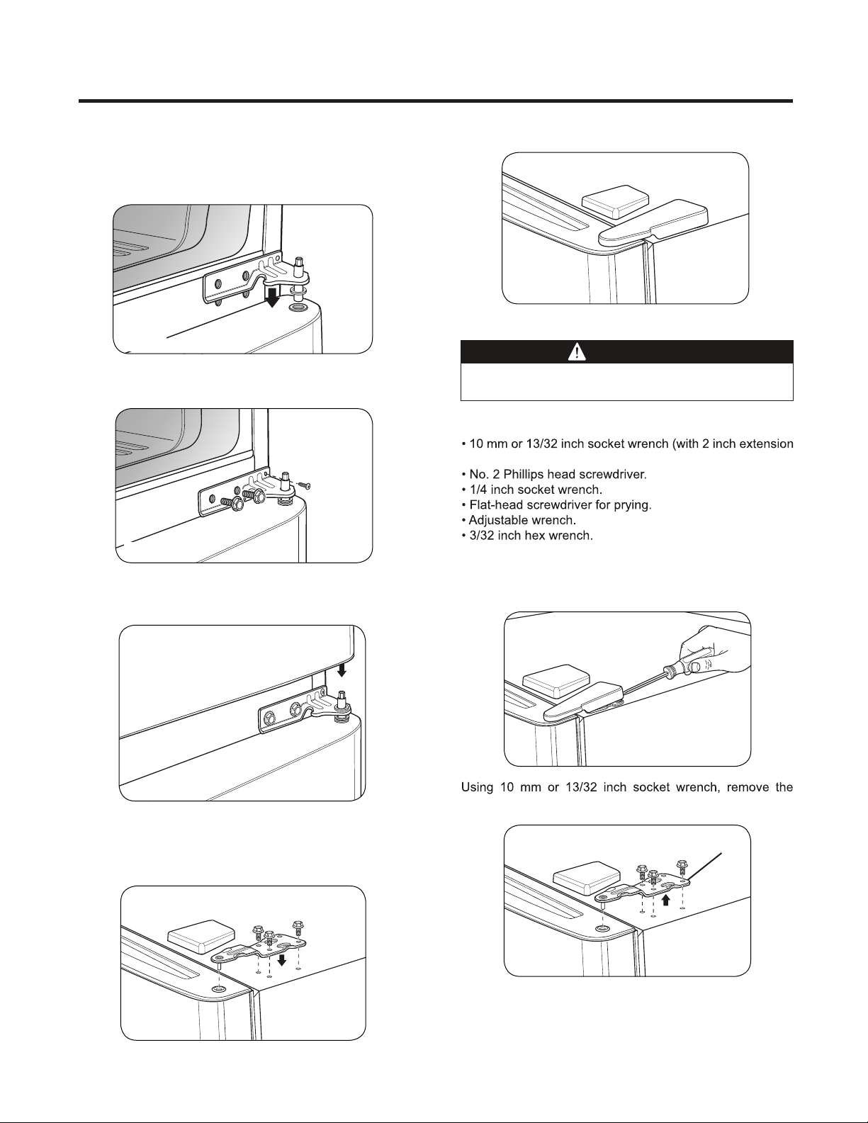
3. DISASSEMBLY
4. TROUBLE SHOOTHING
4-1 Compressor activation defect
4-2 Another electric components
4-3 Service Diagnosis Chart
5. COMPRESSOR
6. CIRCUIT DIAGRAM
7. TROUBLESHOOTHING
7-1 Compressor and Electric Components
7-2 PTC and OLP
7-3 Other Electric Components
7-4 Service Diagnosis Chart
7-5 Refrigerant Cycle
9. CIRCUIT OF MICOM
9-1 Function
11. TROUBLESHOOTHING
12. EXPLODED VIEW
........................................................................
.............................................................................................................
.................................................................................................
.................................................................................................................
..................................................................................................
.....................................................................................
.......................................................................................
.............................................................................................
................................................................................................................
.........................................................................................................
...................................................................................................
.......................................................................
.............................................................................................................
.........................................................................................
.............................................................................................
........................................................................................................
........................................................................................................
............................................................................................................................
.................................................................................................
..........................................................................................................
1
2
3
4
10
10
16
17
18
20
21
21
22
23
24
25
27
28
35
49
Copyright © 2021 LG Electronics Inc. Todos los derechos
reservados. Solo para propósitos de entrenamiento y servicio.