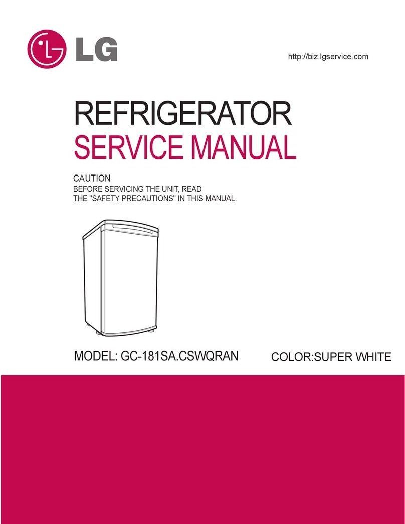
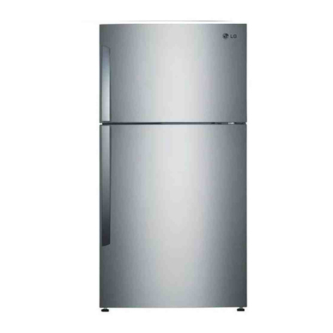
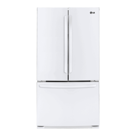
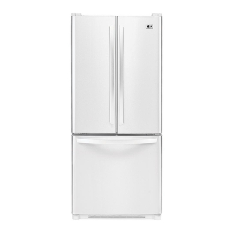
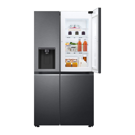
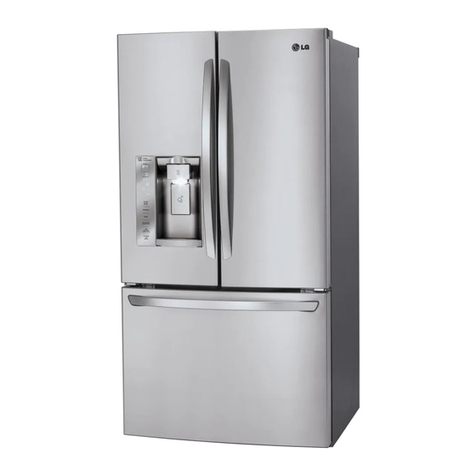
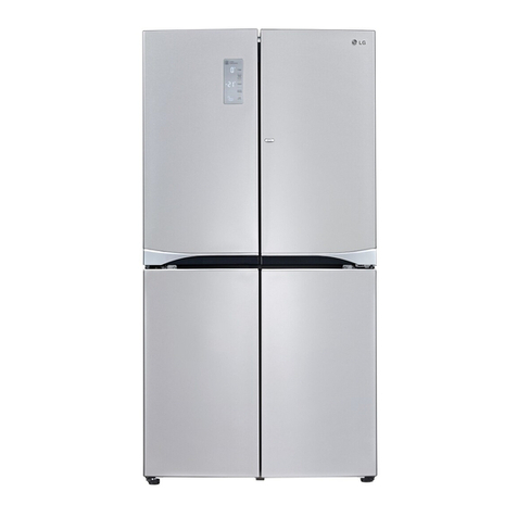
LG LSC 26905TT User manual

CAUTION
PLEASE READ THE SAFETY PRECAUTIONS OF THIS MANUAL CAREFULLY
BEFORE REPAIRING OR OPERATING THE REFRIGERATOR
REFRIGERATOR
SERVICE MANUAL
MODEL: LSC26905TT
COLOR: STAINLESS
WESTERN BLACK
STAINLESS
TITANIUM
NEO TITANIUM
http://biz.lgservice.com

WARNINGS AND PRECAUTIONS FOR SAFETY ................................................................................................................ 3
SPECIFICATIONS................................................................................................................................................................... 4
PARTS IDENTIFICATION ....................................................................................................................................................... 7
HOW TO INSTALL THE REFRIGERATOR .......................................................................................................................... 11
HOW TO ADJUST THE DOOR HEIGHT............................................................................................................................ 11
FILTER ............................................................................................................................................................................... 12
HOW TO CONTROL THE ICEMAKER WATER SUPPLY.................................................................................................. 14
MICOM FUNCTION .............................................................................................................................................................. 16
EXPLANATION OF MICOM CIRCUIT .................................................................................................................................. 32
EXPLANATION OF PWB CIRCUIT .....................................................................................................................................32
PWB PARTS DIAGRAM AND LIST.....................................................................................................................................59
PWB CIRCUIT DIAGRAM ...................................................................................................................................................79
ICEMAKER AND DISPENSER WORKING PRINCIPLES AND REPAIR ............................................................................87
WORKING PRINCIPLES.................................................................................................................................................... 87
FUNCTION OF ICEMAKER ............................................................................................................................................... 88
ICEMAKER TROUBLESHOOTING.................................................................................................................................... 91
ICEMAKER CIRCUIT ..........................................................................................................................................................92
CIRCUIT................................................................................................................................................................................ 94
TROUBLE DIAGNOSIS........................................................................................................................................................ 98
TROUBLESHOOTING ....................................................................................................................................................... 98
FAULTS ............................................................................................................................................................................ 108
SEALED SYSTEM REPAIR ............................................................................................................................................. 125
HOW TO DEAL WITH CLAIMS........................................................................................................................................ 132
HOW TO DISASSEMBLE AND ASSEMBLE..................................................................................................................... 137
DOOR............................................................................................................................................................................... 137
HANDLE ........................................................................................................................................................................... 138
FAN SHROUD GRILLE .................................................................................................................................................... 139
ICEMAKER ASSEMBLY................................................................................................................................................... 139
WATER-VALVE DISASSEMBLY METHOD ...................................................................................................................... 140
FAN AND FAN MOTOR DISASSEMBLY METHOD ......................................................................................................... 140
DISPENSER..................................................................................................................................................................... 141
EXPLODED VIEW .............................................................................................................................................................. 143
REPLACEMENT PARTS LIST ........................................................................................................................................... 166
CONTENTS
- 2 -
Please observe the following safety precautions to use the
refrigerator safely and correctly and to prevent accident or
injury when servicing.
1. Be careful of an electric shock. Disconnect power cord
from wall outlet and wait for more than three minutes
before replacing PWB parts. Shut off the power
whenever replacing and repairing electric components.
2. When connecting power cord, wait for more than five
minutes after power cord was disconnected from the
wall outlet.
3. Check if the power plug or card is pinched between the
refrigerator and the wall. If the cord is damaged, it could
cause fire or electrie shock.
4. If the wall outlet is overloaded, it may cause a fire. Use a
dedicated circuit for the refrigerator.
5. Be sure the outlet is grounded, This is particularly
important in wet or damp areas.
6. Use standard electrical components.
7. Make sure hooks are correctly engaged.
Remove dust and foreign materials from the housing
and connecting parts.
8. Do not fray, damage, run over, kink, bend, pull out, or
twist the power cord.
9. Please check for evidence of moisture intrusion in the
electrical components. Replace the parts or mask with
insulation tape if moisture intrusion was confirmed.
10. Do not touch the icemaker with hands or tools to
confirm the operation of geared motor.
11. Do not suggest that customers repair their refrigerator
themselves. This work requires special tools and
knowledge. Non-professionals could cause fire, injury,
or damage to the product.
12. Do not store flammable materials such as ether,
benzene, alcohol, chemicals, gas, or medicine in the
refrigerator.
13. Do not put anything on top of the refrigerator,
especially something containing water, like a vase.
14. Do not put glass bottles full of water into the freezer.
The contents will freeze and break the glass period.
15. When you scrap or discard the refrigerator, remove the
doors and dispose of it where children are not likely to
play in or around it.
WARNINGS AND PRECAUTIONS FOR SAFETY
- 3 -

SPECIFICATIONS
- 6 -
ITEMS SPECIFICATIONS
DIMENSIONS 908
X
896
X
1771 mm
W
X
D
X
H (3511/16
X
355/16
X
6911/16 in.)
NET WEIGHT 130 kg (286.6 lbs.)
COOLING SYSTEM Fan Cooling
TEMPERATURE CONTROL Micom Control
DEFROSTING SYSTEM Full Automatic
Heater Defrost
INSULATION Cyclo-Pentane
COMPRESSOR PTC Starting Type
EVAPORATOR Fin Tube Type
CONDENSER Wire Condenser
REFRIGERANT R134a (185g) (61/2oz.)
LUBRICATING OIL FREOL @10G (320 cc)
ITEMS SPECIFICATIONS
DRIER MOLECULAR SIEVE XH-7
CAPILLARY TUBE ID Ø0.83
FIRST DEFROST 4 - 5 Hours
DEFROST CYCLE 13 - 15 Hours
DEFROSTING DEVICE Heater, Sheath
ANTI-SWEAT HEATER Dispenser Duct Door Heater
Dispenser Heater
ANTI-FREEZING HEATER Water Tank Heater
Damper Heater
FREEZER LAMP 40W (1 EA)
REFRIGERATOR LAMP 40W (2 EA)
DISPENSER LAMP 15W (1 EA)
724 mm (281/2in.)
1004 mm (391/2in.)
908 mm (3911/16 in.)
779 mm (305/8in.)
829 mm (325/8in.)
892 mm (351/8in.)
1261 mm (495/8in.)
1741.5 mm (681/2in.)
1746.5 mm (683/4in.)
1771 mm (6911/16 in.)
Front View Top View
3. Ref No. :LSC26905TT (Refer to appendix)

4. Ref No. : LSC26905TT (Refer to appendix)
PARTS IDENTIFICATION
- 10 -
Display Frame
Dispenser Lamp
Ice & Water
Dispenser Button
PWB Cover
Water Tubes
Lamp
Shelf
Snack Drawer
Vegetable Drawer
Vegetable Drawer
Door Rack
Shelf
Door Rack
Lamp
Lower Cover
Dairy Product Corner
Door Rack
Door Rack
Drawer
(Plastic)
Freezer
Compartment
Refrigerator
Compartment
Automatic
Icemaker
Door Rack
Shelf
Door Rack
Water Filter

1. How to adjust the Refrigerator Door Height
■Make the refrigerator level first. (If the refrigerator is not installed on a flat floor, the height of freezer and refrigerator
door may not be the same.)
1. If the freezer door is lower than the refrigerator
door:
2. If the freezer door is higher than the refrigerator
door:
Insert a driver into the groove if the adjusting
screw and turn in the direction of the arrow (clockwise)
until the refrigerator is level.
HOW TO INSTALL THE REFRIGERATOR
- 11 -
Adjusting
Screw
Driver
Height
Difference
Height
Difference
Height
Difference
Height
Difference
1
2

2. Filter
Replace the filter when the indicator light comes on or the
performance of the icemker or water dispenser decreases
noticeably.
After changing the water filter cartridge, reset the water
filter status display and indicator light by pressing and
holding the BUTTON for 3 seconds. (page 18)
1. Remove the old cartridge.
Twist the knob of the cartridge counter clockwise.
When the cartridge is removed, you will feel it click .
Pull out the cartridge.
NOTE: There will be some water (25cc) in the filter
cartridge. Some spilling may occur. Catch it in a
bowl or towel.
2. Replace with a new cartridge.
Take the new cartridge out of its packaging and remove the
protective cover from the o-rings.
With cartridge knob in the vertical position, push the new
filter cartridge into the cover until it stops.
If you can’t turn the filter from side to side, it isn’t fully
inserted. Push it in firmly and twist it into place. You will
feel and hear the snap when it clicks into place.
Using the handle, twist the cartridge clockwise about 1/4
turn.
3. Flush the Water System After Replacing Filter Dispense
water through the water dispenser for 3 minutes to
purge the system.
There may be a little air in the line, causing noise or
hissing. Run the water at the dispenser until the hissing
stops to purge the air from the system.
NOTE: - To purchase replacement water filter cartridges,
visit your local appliance dealer or part distributor.
- You can also visit our website :
www.lgeus.com or call 1-800 -243-000.
FITER ASSEMBLY, WATER
HOW TO INSTALL THE REFRIGERATOR
- 12 -
LG MDL PART NO MAKER
GR-L267BV(T)R
GR-L267BV(T)RA 5231JA2006A CUNO
GR-L267BS(T,S)PA
GR-L267BNRY 5231JA2002A CUNO

■Install Water Filter (Applicable to some models only)
■Before Installing Water Filter
1. Before installing the filter, take out the top shelf of the
refrigerator after tilting it to the direction and lifting it
to the direction and move it to the lower part.
2. Remove the lamp cover by pressing the protrusion
under the cover and pulling the cover to the front.
■Installing water filter
1. Initial installation of water filter
Remove the filter substitute cap by turning it
counterclockwise by 90 degrees and pulling it down.
Note : Keep the cap safe to use it later when you do not
use the filter.
Remove the red cap from the filter and attach the
sticker. Insert the upper part of the filter after aligning
with the guideline marked on the control box, and fasten
it by turning it clockwise by 90 degrees.
Note : Check that the guideline and the fastening
indication line are aligned.
2. Replacement of water filter
While holding the lower part of the filter, turn it
counterclockwise by 90 degrees and pull it down.
Note : Check that the guideline and the loosening
indication line are aligned.
■After installing water filter
Reassemble the lamp cover and the top shelf of the
refrigerator. To place the top shelf of the refrigerator, raise
the front part of the shelf a bit so that the hook of the shelf
is fits into the groove.
To purge the water filter system, let the water run for at
least 3 minutes.
NOTE : Open the refrigerator and check for water droplets
on the shelf under the filter.
HOW TO INSTALL THE REFRIGERATOR
Control Box
Aligning with the guide line
and the fastening indication line
Control Box
Aligning with the guide line
and the loosening indication line
Separation
of Red Cap
Sticker
Substitute
Cap
- 13 -

3. How to Control the Amount of Water Supplied to Icemaker.
3-1. Confirm the amount of water supplied to the icemaker.
1. Pull out the ice bin shelf in the upper part of the freezer compartment.
Caution : •Do not put hands or tools into the chute to confirm
the operation of geared motor.
It may damage the refrigerator or hurt your hands.
2. Trun on the electricity after connecting water pipe.
1) Press the test switch under the icemaker for two seconds as shown below.
2) The bell rings(ding~dong), the ice tray rotates, and water comes out the icemaker water tube.
3) The water is supplied into the tray two or three times. The amount is smal each time.
Put a container under the ice tray and press test switch.
4) When the ice tray rotates, the water in it will spill. Collect the spilled water and discard it.
5) When ice tray has finished rotation, water comes out the water tube. Check the amount that goes into the ice tray. (Refer
to the drawing below. The optimum amount is 110cc.(almost 4 oz.))
* It is acceptable is the adjusted water level is less than the optimum level.
HOW TO INSTALL THE REFRIGERATOR
- 14 -
21
Test Switch
Confirm the amount
of water
Icemaker
Too much
Too little
Optimum level

3-2. Control the amount of water supplied to the icemaker.
Caution : • Unplug the power cord from the wall outlet and wait at least three minutes before removing the main PWB
cover. 310 Volts are present in the control panel.
1. Disconnect PWB cover from the upper part of the refrigerator.
2. Adjust the amount of water supplied by using the DIP
switches.
■Water Supplying Time Control Option
1) The water supplying time is set at five seconds when the refrigerator is delivered.
2) The amount of water supplied depends on the setting time and water pressure (city water pressure).
3) If the ice cubes are too small, increase the water supplying time. This happens when too little water is supplied into the ice tray.
4) If the ice cubes stick togther, decrease the water supplying time. This happens when too much water is supplied into the ice tray.
Caution : When adjusting the amount of water supplied, adjust step by step. Otherwise the water may spill over.
3. When the adjustment of the control switch for the amount of water supplied is complete, check the level of water in the ice
HOW TO INSTALL THE REFRIGERATOR
- 15 -
(+) Driver
1
ON
Switch ON
Switch OFF 23
Confirm the amount
of water
Optimum level
* The quantity of water
supplied depends on DIP
switch setting conditions
and water pressure as it
is a direct tap water
connection type. (the
water supplied is
generally 80 cc to 120 cc)
* DIP switch is on the main
PWB.
GR-L267BV(T)R (Refer to an appendix)
GR-L267BNRY
GR-L267BV(T)RA (Refer to an appendix)
GR-L267BV(T,S)PA
No DIP SWITCH SETTING
S1 S2
DIP SWITCH SETTING
S1 S2 S3
1
2
3
4
5
6
7
8
OFF OFF 6.5 SEC
ON OFF 5.5 SEC
OFF ON 7.5 SEC
ON ON 8.5 SEC
OFF OFF OFF 6.5 SEC
ON OFF OFF 5.5 SEC
OFF ON OFF 6 SEC
ON ON OFF 7 SEC
OFF OFF ON 7.5 SEC
ON OFF ON 8 SEC
OFF ON ON 9 SEC
ON ON ON 10 SEC
WATER
SUPPLY TIME
WATER
SUPPLY TIME
REMARKS

1. Monitor Panel
1-1. GR-L267BV(T)RA, GR-L267BV(T, S)PA (Refer to appendix)
1-2. GR-L267BV(T)R (Refer to appendix)
1-3. GR-L267BNRY (Refer to an appendix)
MICOM FUNCTION
- 16 -
EXPRESS/JET FRZ DISPENSER FREEZER REFRIGERATOR FILTER/LIGHT LOCK
Dispenser Selection
Button
Express Freezer/Jet Freezer
Function Selection Button
Dispenser and Button
Lock Button
Dispenser Lamp On/Off Button/
Filter Status Display RESET Button
Temperature Adjustment Button
For Refrigerator Compartment
Temperature Adjustment Button
for Freezer Compartment
EXPRESS
FRZ
(EXPRESS)
ON
(JET)
CUBE
ROOM TEMPERATURE
LOCK
DISPENSER & BUTTON
F
WATER
CRUSH
C
3 SECS
DIGITAL CONTROL
FRZ TEMP
F
C
F
C
REF TEMP
FILTER RESET
HOLD 3SECS
FILTER
EXPRESS DISPENSER FREEZER
REFRIGERATOR
FILTER RESET/LIGHT
LOCK
EXPRESS
FRZ
ON
CUBE
LOCK
DISPENSER
BUTTON
WATER
CRUSH
3 SECS
DIGITAL CONTROL
FRZ TEMP REF TEMP
COLDEST
COLD
FILTER RESET
HOLD 3SECS
FILTER

1-4. Display Second Function
1. Buzzer sound mute Mode
The buzzer sound is set to OFF.
It activates by sounding the recognition sound of Ding~ after pressing and holding Express FRZ button more than 5
seconds. It inactivates when resetting the mode power.
2. Display Power saving Mode
Power Save Mode puts the display into standby mode until the door is opened.
To put the display into Power Save Mode, press and hold the FREEZER and EXPRESS FRZ buttons simultaneously for 5
seconds until the Ding~ sounds. (Use both buttons for this towork.) When Power Save Mode is activated, the display
remains OFF unless a door is opened or a button is pressed. The display will return to the OFF position after 30 seconds'
inactivity.
To remove the display from Power Save Mode, press and hold the FREEZER and EXPRESS FRZ buttons
simultaneously for 5 seconds until the Ding~ sounds. The Power Save Mode default setting is OFF after a power
interruption.
3. Change Display Degree to Centigrade Mode from Fahrenheit Mode
To change temperature display from Fahrenheit to Celsius press and hold FREEZER and REFRIGERATOR buttons
simultaneously for more than 5 seconds. Do the same to convert back to Celsius.
4. Exhibition with Demo Mode
Demo mode is available for displaying the refrigerator in a sales setting or similar condition.
It allows the display, dispenser, lights, and fan to operate without running the compressor.
To enter the DEMO mode, press and hold the REFRIGERATOR and EXPRESS FRZ buttons simultaneously for 5
seconds until the Ding~ sounds.
To exit the DEMO mode and return to normal operation, press and hold the REFRIGERATOR and XPRESS FRZ buttons
simultaneously for 5 seconds until the Ding~ sounds again.
The refrigerator will default to the NORMAL mode (DEMO mode OFF) if the power fails.
MICOM FUNCTION
- 17 -
EXPRESS/JET FRZ DISPENSER FREEZER REFRIGERATOR FILTER/LIGHT LOCK
Display Power
Saving Mode
Exhibition Mode
EXPRESS
FRZ
(EXPRESS)
ON
(JET)
CUBE
ROOM TEMPERATURE
LOCK
DISPENSER & BUTTON
F
WATER
CRUSH
C
3 SECS
DIGITAL CONTROL
FRZ TEMP
F
C
F
C
REF TEMP
FILTER RESET
HOLD 3SECS
FILTER
Change Display Degree from
Fahrenheit to Centigrade Mode
Buzzer mute
Mode

2. Description of Function
2-1-1. Function of Temperature Selection
* The temperature can vary ±3°C (26.6 °F ~ 37.4 °F) depending on the load condition.
❉Press the button to cycle through the settings in this order: (Medium) ➝(Medium High) ➝(High) ➝(Low) ➝
(Medium Low).
• The temperature displayed is the SET temperature, NOT the actual temperature inside the refrigerator. The actual
temperature varies, depending upon the temperature of items put into the refrigerator and other variables.
• It takes the refrigerator a while to get down to the set temperature from the initial power- on. Wait at least 24 hours after
initial power- up to put food into the refrigerator. If the temperature is unsatisfactory, adjust it and wait 24 hours. It may
take three or four days to get the adjustment to your satisfaction.
• The freezer is automatically set to MEDIUM HIGH if the icemaker is set to ON.
2-1-2. Outside temperature display function
1. The ambient temperature sensor is located under the upper right hinge cover. This sensor reads the temperature of the
room and displays it in the upper right corner of the display.
2. The ambient temperature is displayed between 16 °F and 120 °F.Outside of that range, the display willshow Er.
3. Since the ambient temperature sensor is located at the hinge, its reading may differ from other thermometers in the room.
MICOM FUNCTION
- 18 -
Division Power Initially On 1st Press 2st Press 3th Press 4th Press
Setting
temperature
Temperature
Control Medium Medium High High Low Medium Low
Freezer Control
-2 °F -5 °F -8 °F 7 °F 1 °F
Refrigeration 37 °F 34 °F 32 °F 46 °F 41 °F
Control
5
4
3
2
1
5
4
3
2
1
5
4
3
2
1
5
4
3
2
1
5
4
3
2
1

2-1-3. Lock Function (dispenser and display button lock)
1. In power application of refrigerator, the LOCK text is turned off at the right side of lock graphic of display with the lock
replease status.
2. If desiring to lock the dislay the dispenser and control panel, push on the LOCK button more than 3 seconds. LOCK text
is turned on at the right side of lock graphic of display with lock status.
3. The buzzer sound and control panel and dispenser function is not performed even if pressing display button other than
lock key in the lock status.
4. If desiring to release the lock status and pressing the lock button more than 3 seconds. LOCK text is turned off at the right
side of lock graphic of display with the lock release status.
2-1-4. Filter condition display function
1. There is a replacement indicator light for the water filter cartridge on the dispenser.
2. Water filter needs replacement once six months.
3. Water filter light and FILTER RESET HOLD 3 SECONDS text turn on to tell you need to replace the filter soon.
4. After replace the filter, press and hold the lock button more than 3seconds.
Then water filter light and FILTER RESET HOLD 3 SECONDS text turn off with reset status.
MICOM FUNCTION
- 19 -
LOCK
DISPENSER & BUTTON
3 SECS
LOCK
DISPENSER & BUTTON
3 SECS
LOCK CONTROL
Ex) Select
LOCK
Ex) Select
LOCK again
Ex) Select
LOCK
Ex) Select
LOCK again
In initial Power On
/ Filter RESET
Replace indicator
light on
Classification
Filter Status
Display
FILTER RESET
HOLD 3SECS
FILTER
FILTER RESET
HOLD 3SECS
FILTER
In initial Power On
/ Filter RESET
Replace indicator
light on
Classification
Filter Status
Display
LED LED(GR-L267BNRY)
LED(GR-L267BNRY)

2-2. Dispenser use selection
You can select water or ice.
❉Please select water, cruched ice, and cubed ice by pressing the button
as you desire.
❉Use your cup to press lightly on the actuator.
•Each graphic is indicated for the selected function.
•You’ll hear a CLICK when the ice door closes 5 seconds after ice is
dispensed.
REFERENCE : Hold your cup in the dispenser for a few seconds after
dispensing ice or water to catch the last few drops or pieces of
ice.
2-3. Express Freezing/JET Freezing Selection
Select this function to expedite freezing.
•Press the button to cycle to toggle between the settings.
•The arrow mark graphic remains at the ON status after flickering 4 times when selecting Special Refrigeration EXPRESS
FRZ or JET FRZ.
•Expressing freezer or jet freezer function automatically turns off if a fixed time passes.
2-4. Dispenser Light
•Dispenser switch or dispenser light button turns the dispenser light ON and OFF.
•The dispenser light function is repeated following below whenever pressing FILTER RESET/LIGHT button.
•If dispenser light continuously turns on more than 7 minutes with dispenser light button, the dispenser light turns off
automatically period.
MICOM FUNCTION
- 20 -
DISPENSER
LED
LED(GR-L267BNRY)
CUBE
WATER
CRUSH
Pressing
Switch
LED (GR-L267BV(T,S)PA) (Refer to an appendix)
LED (GR-L267BNRY)
(Refer to an appendix)
LED (GR-L267BV(T)R, GR-L267BV(T)RA)
(Refer to an appendix)
EXPRESS/JET FRZ
EXPRESS/JET FRZ EXPRESS
FRZ
EXPRESS EXPRESS EXPRESS
ON
EXPRESS
FRZ
ON
JET JET JET
Dispenser Iight
ON/OFF LED
DISPENSER

2-5. Express freezing
1. Express freezing increases the cooling speed in the freezer by running the fan and the compressor simultaneously.
2. Express freezing is released if the power fails and is restored.
3. The temperature setting is not changed when Express Freeze is selected.
4. You can change the temperature in the freezer and the refrigerator even if Express Freeze has been selected and is in
progress.
5. The refrigerator operates independently of the Express Freeze setting and operation.
6. At the end of the Express Freeze cycle, the freezer defaults to its original setting.
7. If frost removal starting time is arrived during Express freezing, Express freezing operation is done only for the remaining
time after completion of frost removal when the Express freezing operation time passes 90 minutes. If passing 90
minutes, Express freezing operation is done only for 2 hours after completion of frost removal.
8. If pressing Express freezing button during frost removal, the Express freezing LCD or LED is turned on but if pressing the
Express freezing, compressor operates after the remaining time has passed.
9. If selection Express freezing within 7 minutes (delay for 7 minutes of compressor) after the compressor stops,
compressor operates after the remaining time has passed.
10. The Freezer fan motor operates at the high speed of RPM during operation of Express freezing.
2-6. Jet Freezing (GR-L267BV(T,S)PA (Refer to appendix)
1. Jet Freeze increases the cooling speed in the Jet Freeze area of the freezer by running both the compressor and the Jet
Freeze Box fan.
2. Jet freezing is released if the power fails and is restored.
3. The set temperature display is not changed by selecting Jet Freeze.
4. If Jet Freeze is selected,the compressor and the freezer fan will both operate.
The refrigerator temperature will drop and the Jet Freeze box motor will run for a maximum of 2 hours
After that, Jet Freeze is released and the freezer defaults to its original setting.
5. To keep the Jet Freeze fan motor from becoming ice- bound, the controller spins it up for 10 seconds every hour.
6. The Jet Freeze fan motor will not be detected as a failure because it is a 12 V DC motor.
7. The Jet Freeze fan motor will run for one minute if the freezer adjust button is pressed and held for over 1 second.
MICOM FUNCTION
- 21 -

2-7. OptiChill Function (GR-L267BV(T,S)PA Model) (Refer to appendix)
1. The OptiChill is positioned at the bottom of fresh food room separately and allow the user to select and adjust a desired
temperature according to kinds of food such as meat, fish, vegetables and fruits and so on. The selected temperature to
any kinds of food let user to keep their food longer.
2. OptiChill comprises of OptiChill sensor at the rear of OptiChill and a damper between OptiChill and freezer room and a
temperature adjusting display at the top of it.
3. When OptiChill is turned on, it defaults to FRUIT VEGE. If only the refrigerator door is opened, the OptiChill LED will be
ON.
4. Each consecutive press of the SELECT button cycles through the options in this order and shows a target temperature:
FRUIT VEGE (39°F) →CHILED ROOM (30°F) →PARTIAL FREEZING (27°F) →FRUIT VEGE (39°F).
5. The OptiChill temperature is read by the MICOM. The MICOM will close and open the damper based upon the
temperature.
6. To keep the OptiChill damper from becoming ice- bound, the controller opens and/ or closes it every hour.
MICOM FUNCTION
- 22 -
°F / SET TEMP
/ TIME REMAINING
MIN
FRUIT
VEGE
CHILED
ROOM
PARTIAL
FREEZING
SELECT
HR
Display 27°F30°F39°F
NOTCH Partial
Freezing
Chilled
Room
Fruit
VEGE

2-8. Control of variable type of freezing fan
1. To increase cooling speed and load response speed, MICOM variably controls freezing room fan motor at the high speed
of RPM and standard RPM.
2. MICOM only operates in the input of initial power or express freezing operation or load response operation for the high
speed of RPM and operates in the standard RPM in other general operation.
3. If opening doors of freezing / cold storage room or home bar while fan motor in the freezing room operates, the freezing
room fan motor normally operates (If being operated in the high speed of RPM, it converts operation to the standard
RPM). However, if opening doors of freezing room or home bar, the freezing room fan motor stops.
4. As for monitoring of BLDC fan motor error in the freezing room, MICOM immediately stops the fan motor by determining
that the BLDC fan motor is locked or fails if there would be position signal for more than 115 seconds at the BLDC motor.
Then it displays failure (refer to failure diagnosis function table) at the display part of refrigerator, the BLDC motor doesn’t
operate more. If you want to operate the BLDC motor, turn off and on power resource.
2-9. Control of cooling fan motor
1. The cooling fan motor performs ON/OFF control by linking with the COMP.
2. It controls at the single RPM without varying RPM.
3. Failure sensing method is same as in fan motor of freezing fan motor (refer to failure diagnosis function table for failure
display). (Except GR-L267BNRY)
2-10. Door opening alarm
1. Buzzer generates alarm sound if doors are not closed even when more than a minute consecutively has passed with
doors of freezer / refrigerator or home bar opened.
2. After the door has been open for one minute, the buzzer sounds for 1/2 second and then sounds three times every 30
seconds.
3. If all doors are closed when the alarm sounds, it is cancelled immediately.
2-11. Ringing of button selection buzzer
1. The ding~ will sound whenever a button is pressed.
MICOM FUNCTION
- 23 -
Doors of freezing/
cold storage room
or home bar
BUZZER
Closing
Opening
Within
1 minute
1 minute
30
seconds
30
seconds
30
seconds
Opening
Closing Closing
3 Times 3 Times 3 Times 3 Times

2-12. Ringing of compulsory operation, compulsory frost removal buzzer
1. If pressing the test button in the Main PCB, a beep will sound.
2. In selecting compulsory operation, alarm sound is repeated and completed in the cycle of On for 2/10 second and Off for
1 8/10 second three times.
3. In selecting compulsory frost removal, alarm sound is repeated and completed in the cycle of On for 2/10 second , Off for
2/10 second, On for 2/10 second and Off for 1 4/10 second three times.
2-13. Defrost function
1. Defrost is performed whenever total operation time of compressor becomes 7 ~ 7 1/2 hour.
2. In providing initial power (or returning power failure), frost removal starts whenever total operation time of compressor
becomes 4 ~ 4 1/2 hour.
3. Defrost is completed if temperature of a defrost sensor becomes more than 5°C after starting defrost. The defrost cycle
will fail if there frigerator does not reach a temperature of 5°C (9 °F)two hours into the defrost cycle.
4. The defrost cycle will not operate of the defrost sensor fails, arcs, or shorts out.
2-14. Refrigerator lamp automatically off
•Refrigerator lamp turns on and off by refrigerator door switch.
•If refrigerator lamp continuously turns on more than 7 minutes, the refrigerator room lamp turns off automatically period.
MICOM FUNCTION
- 24 -

2-15. Sequential operation of built-in product
Built-in products such as compressor, frost removal heater, freezing room fan, Cooling fan and step motor damper are
operated sequentially as follows to prevent noise and part damage due to simultaneous operation of several parts in
applying initial power and completing test.
MICOM FUNCTION
- 25 -
Function Load Operation Sequence Remark
In applying Initial power TEST MODE
When temperature
of a frost removal
sensor becomes
more than 45°C
(113°F) (In purchase,
movement)
If error occurs
during operation,
initial operation is
not done.
■Sequence of
load operation
when closing
Freezer and
Refrigerator.
If pressing switch
once more in the
test mode 2 or
temperature of a
frost removal
sensor is more
than 45°C (113°F),
it immediately
returns to the test
mode for initial
operation
(COMP operates
after 7 minutes).
When
temperature of a
frost removal
sensor becomes
less than 45°C
(113°F) (In power
failure, service)
Test mode 1
(Compulsory
function)
Test mode 2
(Compulsory frost
removal)
POWER
ON
COMP
ON
F-FAN
&
C-FAN
ON
R-STEP
MOTOR
DAMPER
ON
OPTICHILL
STEP
DAMPER
MOTOR
ON
FROST
REMOVAL
HEATER
OFF
FROST
REMOVAL
HEATER
ON
DAMPER
&
DUCT DOOR
&
OPTICHILL
HEATER ON
DAMPER
&
DUCT DOOR
&
OPTICHILL
HEATER OFF
0.3
sec.
6.0
sec.
0.3
sec.
0.3
sec.
0.3
sec.
POWER
ON
0.3
sec.
PIPE
&
DISP'
HEATER
OFF
0.3
sec. COMP
ON
0.3
sec. F-FAN
&
C-FAN
ON
0.3
sec. R-STEP
MOTOR
DAMPER
ON
0.3
sec.
OPTICHILL
STEP
DAMPER
MOTOR
ON
PIPE
&
DISP'
HEATER
ON
TEST
SWITCH
(PRESS
Once)
OTHER
LOAD
OFF
COMP
ON
F-FAN
&
C-FAN
ON
R-STEP
MOTOR
DAMPER
ON
OPTICHILL
STEP
DAMPER
MOTOR
CLOSE
TEST
SWITCH
(PRESS
2 Times)
COMP
OFF
F-FAN
&
C-FAN
OFF
FROST
REMOVAL
HEATER
ON
R-STEP
MOTOR
DAMPER
CLOSE
0.3
sec.
0.3
sec.
0.3
sec.
0.3
sec.
0.3
sec.
0.3
sec.
0.3
sec.
0.3
sec.
0.3
sec.
0.3
sec.
0.3
sec.
Other manuals for LSC 26905TT
2
Table of contents
Other LG Refrigerator manuals
Popular Refrigerator manuals by other brands

Linea 2000
Linea 2000 DOMO DO981RTKR Instruction booklet

Polar Refrigeration
Polar Refrigeration CD610 instruction manual

Frigidaire
Frigidaire FRS26ZPH Factory parts catalog

Hisense
Hisense H670SIB User's operation manual

Turboair
Turboair TD-4R Installation and operation manual

ETNA
ETNA AKV1178RVS Instructions for use

FUJETA
FUJETA FRDW-450 instruction manual

Beko
Beko CN160240XB user manual

Electrolux
Electrolux RM 122F Operating and installation instructions

Continental Scientific
Continental Scientific Refrigerators and Freezers instruction manual

Sharp
Sharp SJ-286M operating manual

Gram
Gram COMPACT 220 Series user manual