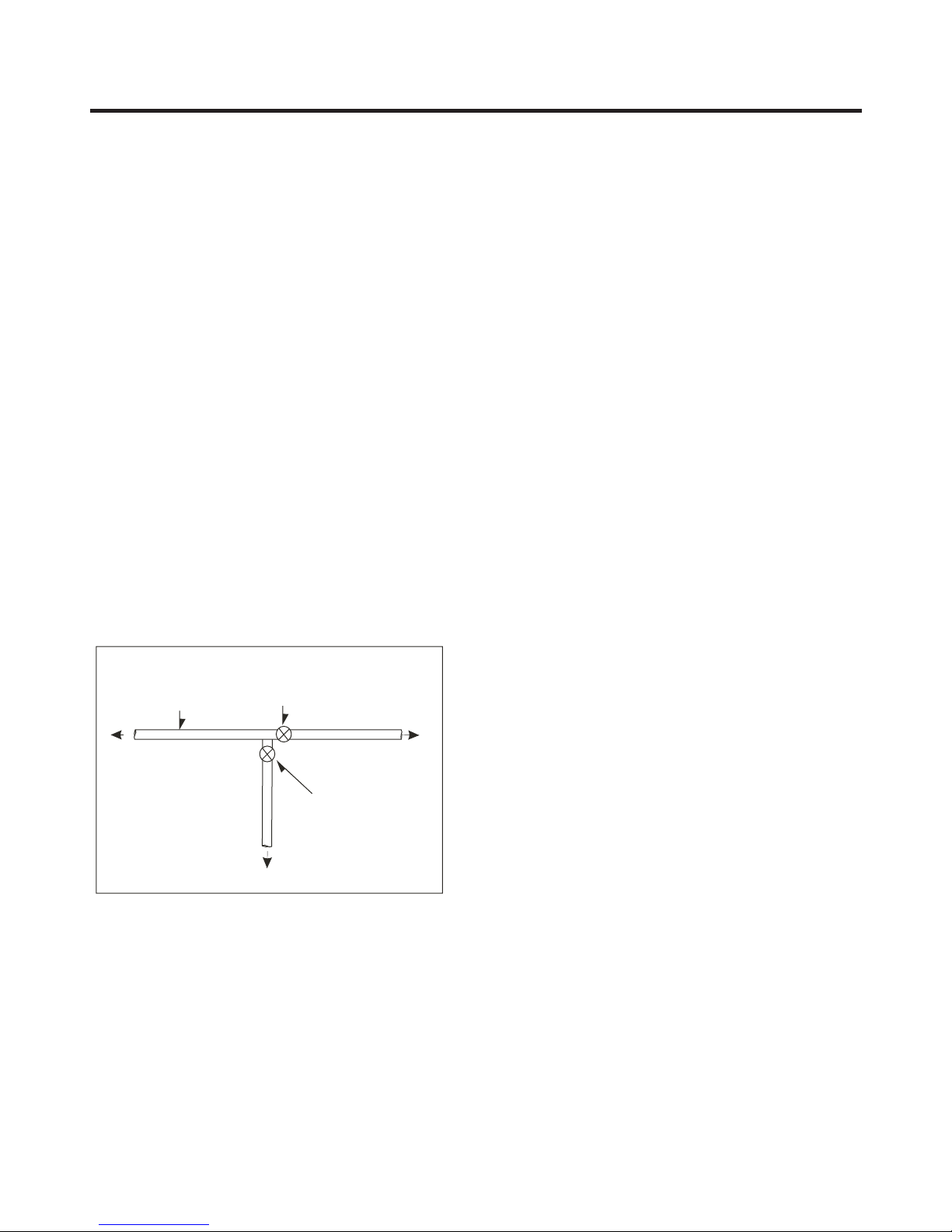
LG LTNS16121V /00 User manual

CAUTION:
PLEASE READ THE SAFETY PRECAUTIONS OF THIS MANUAL CAREFULLY
BEFORE REPAIRING OR OPERATING THE REFRIGERATOR.
REFRIGERATOR
SERVICE MANUAL
MODEL:
LTNS16121V /00

CONTENTS
SAFETY AND SERVICE PRECAUTIONS ........................
.................................................................................................................................................................
..............................................................................................................................................
.....................................................................................................................................................................
.............................................................................................................................................
Removing Refrigerator Door............................................................................................................................................
.................................................................................................................................................................
...........................................................................................................................................................
........................................................................................................................................................
............................................................................................................................................
..........................................................................................................................................................
4. ADJUSTMENTS ...................................................................................................................................................................
..............................................................................................................................................................
...........................................................................................................................................................
................................................................................................................................
..........................................................................................................................................
...............................................................................................................................................
........................................................................................................................
Actions for LED blinking and activation current ...........................................................................................................
..................................................................................................
6.7 LED is blinking 7 times....................................................................................................................................................
6.8 Check compressor and harness .....................................................................................................................................
6.9 Another electric components ..........................................................................................................................................
6.10 Problem Diagnosis Chart ..............................................................................................................................................
6.11 Refrigeration Cycle .......................................................................................................................................................
7. COMPRESSOR ....................................................................................................................................................................
...........................................................................................
9. ERRORS ................................................................................................................................................................................
10. EXPLODED VIEW ..............................................................................................................................................................
...................................................................................................... .
1. SPECIFICATIONS
2. PARTS IDENTIFICATION
3. DISASSEMBLY
3.1 Removing the Freezer Door
3.2
3.3 Switch.............
3.4 Fan & Fan Motor ..
3.5 Refrigerator Lamp ...
3.6 Control Panel Disassembly .
3.7 PCB Disassembly .
5. CIRCUIT DIAGRAM
6.TROUBLESHOOTING
6.1 Compressor activation defect .........
6.2 Compressor service manual .
6.3 Simple verification order ..
6.4 Actions for each number of LED blinking
6.5 ...
6.6 Activation current and LED blinking 6 times .................
8. DESCRIPTION AND FUNCTION OF ELECTRONIC CIRCUIT
3
5
6
7
7
7
7
7
8
8
8
9
11
12
12
13
13
14
14
15
16
17
18
19
20
21
22
27
52
2

3
Extension tube
(load)
Con.
Hen.
Hansen
male
connector
Welding point
Service Tube Extension
Breaking point
Pressure
Vacuum
pump
gauge
SAFETY AND SERVICE PRECAUTIONS
Refrigeration
System
Cylinder of R-134a
Figure # 4
Figure # 1 Figure # 2
Figure # 3
SAFETY PRECAUTIONS
Please read before start your service refrigerator:
1. Disconnect your refrigerator before starting the service
in order to prevent electric discharge
2. Check visually there's not a gas leakage or short circuit
in the refrigerator.
3. In case of realize tests with the connected refrigerator,
use rubber gloves to prevent any accident.
4. If you use any appliance, verify voltage and capacity
regularly.
5. Don't touch metallic parts with humid hands, they could
be adhered.
6. Make sure there's no water drain to electric or metallic
parts.
7. When the freezer door is open and you're checking the
low part, be careful when you lift your head, you could get
hurt.
8. Remove all the glasses, metal or other freely parts when
you tilt the refrigerator.
9. When servicing the evaporator, wear gloves to prevent
injuries from the sharp evaporator fins.
SERVICE CAUTIONS
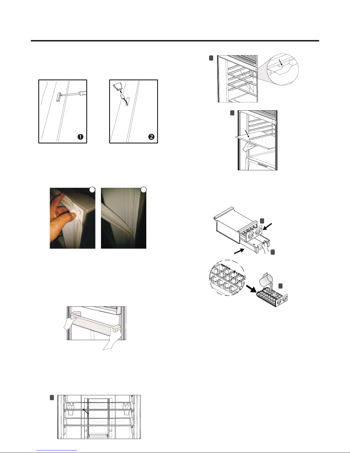
Refrigerant Charge to Compressor
Test compressor operation before recharge the
refrigerant, this is important in order to detect immediately
failures and assure compressor motor reliability.
If the failure has been identified, clean possible R-134a
remnants' in the system breaking the end of the
compressor service tube in the thinnest part (as shown in
Figure #1).
Change the filter and any other damaged part. Disjoint and
pull away the rest of the service tube. Put a new tube
extension in the Hansen male connector. Weld the new
tube (See Figure #2).
It's necessary to realize the welding process with the
opened valve to allow the freely output of gasses from oil.
Use a female connector to join the new tube extension and
the Hansen connector with the vacuum pump (see Figure
#3).
The vacuum process to the system starts as soon as the
pump starts to work. The refrigerator system must be kept
under vacuum until the low pressure meter indicate
Absolute 0 or -1 atm, -760 mmhg (see Figure #3). In any
case, the pump must not be working for more than 30
minutes.
In case of leakage and the vacuum couldn't be realized,
it's necessary to apply a small amount of Freon to the
system. If the vacuum isn't achieved (the lower pressure
meter doesn't indicate Absolute 0 or -1 atm, -760 mmhg)
turn on the refrigerator and try to localize the leakage with
a leakage locator. If you identify a welding failure, open the
valve to normalize the interior pressure with the same
exterior pressure before welding. The molten solder could
be suctioned or expelled and block the cycle tubes if the
vacuum system isn’t stabilized.
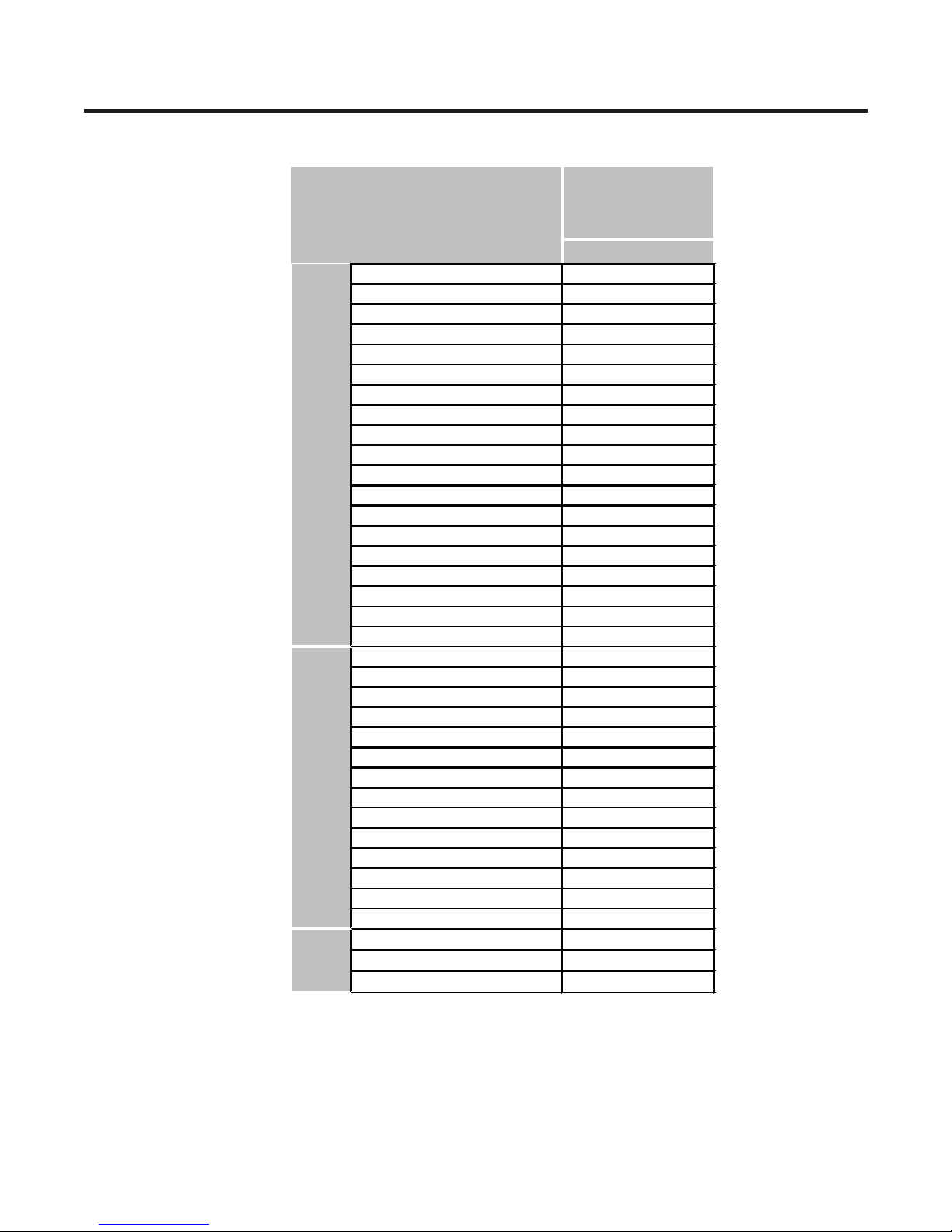
As soon as the vacuum process is finished, charge the
correct refrigerant R-134a gram amount in the system.
Remember, each system use an exact R-134a amount
with a tolerance of ±5 grams (see Figure #4).

4
Vacuum pump
Valve must be closed
after achieving a vacuum
Charging
the cylinder
Refrigerator
System
Refrigerant
Loading tube
Valve should be open
when refilling the gas
Figure # 5
To know the refrigerant amount that contains and that it’s
necessary to be charged to the system, review the
graduated scale cylinder. For example, if we have 750
grams Freon in the cylinder and we must charge 165
grams to the system, this amount will be reached when the
cylinder indicator shows 585 grams. Remember that the
charge indicator shows a lower lever than real. Do this
after select the scale that corresponds to gas pressure
indicated in the pressure meter attached in the column
upper part.
Before performing this operation, make sure that the valve
attached between the vacuum pump and recharge
cylinder is closed in order to keep the Freon to be charged
into the system (see Figure #5).
To make R-134a flow to the system, open the valve which
is attached in the cylinder base and is connected to the
filling tube. The Freon gas amount must not be completely
charged in one session because it could block the
compressor motor; therefore, charge 20~30 grams and
immediately close the valve, the pressure increase and
the compressor motor start the suction, this make
pressure decrease, open the valve again and repeat the
previous steps until rise the established amount of R-134a
gas for the system. When the system is under operation,
the suction pressure must stabilize between 0.30 and 0.6
atmosphere of pressure.

1. SPECIFICATIONS
8
MODEL
LTNS16121V
Platinum Silver 3
31 (W) x 29 (D) x 71 (H)
83 KG
15.7
R134a (133 gr)
Template (N)
115V/60Hz
Fan Cooling
MICOM Control
Heater Defrost
Cyclo Pentanane
BLDC Inverter
Fin Tube
Wire
Molecular Sieve XH-7
ID Ø0.67
4 Hours
7-40 Hours
Heater, Sheath
PCM (Normal)
PET
Curved Handle
LG
4 full
"Twist" type
Yes (LED)
2 Glass
Yes (1)
No
Yes
Yes (1)
No
No
2 full
No
Glass (1)
SPECIFICATIONS
GENERAL FEATURES
Color
Dimensions (in)
Net Weight
Capacity (cu ft)
Refrigerant
Climate Class
Rating
Cooling System
Temperature Control
Defrosting System
Insulation
Compressor
Evaporator
Condenser
Egg Tray
Hygiene Filter
Water Dispenser
Drier
Capillary Tube
First Defrost
Ciclo de Deshielo
Defrost Cycle
FREEZER
Basket
Lamp
Shelf
FRIDGE
Case Material
Door material
Handle Type
Internal Graphics
Basket
Ice Tray
Lamp
Shelf
Vegetable Drawer
Meat Tray
Cover TV (Tray Vegetable)

NOTE: Your refrigerator could have some or all of the features and parts listed below. The location of some
of the parts may not correspond with your model.
2. PARTS IDENTIFICATION
Freezer Shelf (Glass)
Moving Twist’n Serve (Ice Maker)
Internal Temperature Control (Refrigerator)
Refrigerator Lamp (LED)
Refrigerator Shelf (Glass)
Magic Crisper,
Cover for vegetable drawer, it controls humidity
Vegetable Drawer,
Keeps fruits and vegetables fresh
A
6
I
J
K
L
K
H
A
B
C
F
G
D
E
M
I
Leveling Screws
Freezer Big Basket
Temperature Control (Freezer)
Refrigerator Big Basket
Multi Flow Air Duct,
Distributes air to all refrigerator compartments
Egg Tray
B
C
D
E
F
G
H
J
K
L
M
I

3. DISASSEMBLY
3-1. DOOR
7
Freezer Door
Remove the top-hinge cover by using a Phillips screwdriver.
1.
Remove the middle hinge bracket.
2.
Counterclockwise
to remove
Remove the three bolts with either a 10 mm or 3/8 in. socket
wrench, and lift off the top hinge. Set the parts aside.
2.
Top Hinge
Carefully lift up the freezer door from the middle hinge
bracket. Place the door on a non-scratching surface.
3.
Hinge Pin
Middle Hinge Bracket
Carefully lift up the refrigerator door from the bottom hinge
pin. Place it on a non-scratching surface.
3.
Bottom Hinge
Pin
3-2. DOOR HANDLE
Remove the top side of the handle by using a flathead
screwdriver.
Using a Phillips screwdriver, remove the screws that are
attached to the door.
Pull out the handle to remove.
1.
2.
3.
Loosen and remove the two bolts with the socket wrench.
1.
Middle Hinge
Bracket
Bolt
Refrigerator Door
NOTE: Place the top hinge cover
on the cabinet and make sure do
not damage the wires assembled
to it.
Handle Top
Side

8
3-3. DOOR MAGNETIC SWITCH
1 2
3-4. DOOR GASKET
To remove the door gasket, pull it out from any corner until
detaching it. Keep pulling it until remove it from all frame
door.
3-5. DOOR BINS
The door bins are removable for easy cleaning and
adjustment.
1. To remove the bin, simply lift the bin up and pull straight
out.
2. To replace the bin, slide it in above the desired support
and push down until it snaps into place.
3-6. SHELFS
To remove the door switch, remove it with a screwdriver
as shown in below figure.
1.
Disconnect the lead wire from the switch.
2.
1. Lift the back of the shelf from below.
2. Use enough force to lift the shelf and release it from the
holders.
3. Slide the shelf forward to remove it completely.
Shelf
1
Holder
2
Shelf
3
1.Ice bin must be removed in order to remove ice tray
2. Once ice bin is removed, pull out ice trays.
3. Fill ice trays to the indicated level.
4. Icemaker can be moved from one side to the other to suit
your individual storage needs.
1
2
Ice Bin
Ice Trays
3
3-7. ICEMAKER

P/No & MFG Image
3.8 COMPONENTS: MAIN PCB
EBR808608**
9
CON1: Power Source
CON2: AC load
CON5: F-Fan Motor DC
CON6: Display
CON8: Sensor, R-Door Switch, R-LED Lamp
CON9: PCB Assembly Smart Buzzer (SDS)
CON102: OLP Inverter
CON201: Compressor Terminals
CON1
CON201
CON8 CON9
CON5
CON6
CON2 CON102

P/No & MFG Image
3.8 COMPONENTS: LED LAMP (REFRIGERATOR AND FREEZER)
Refrigerator
LED Lamp
EAV61472005
Smart Buzzer
EBR64730409
10
PCB for SDS (System Diagnosis Intelligent)

3-11. PCB
To replace the PCB, you must first remove the connectors that are
connected, you should just press on the lock to remove. The case
PCB that is holding PCB has a lock for secure it, for disassembly
pull out the lock applying som force (as shown in the image above)
while removing PCB. To assemble the new PCB, do the same in
reverse (the cables can not possibly be assembled in an incorrect
connector).
11
5
3-9. FAN MOTOR AND FAN
1. Remove the shelves from freezer compartment.
2. Loose the screw placed in fan grille (use a Phillips
screwdriver ).
3. Hold the upper side of the shelf and pull it out carefully .
4. Remove the plastic cover from the fan by pulling it put
carefully .
5. Unplug the wires.
6. Loose the two screws that hold the motor support and pull
it out in order to remove the fan and fan motor .
7. Remove fan from motor support .
1
2
3
4
5
122
34
5
3-10. CONTROL PANEL DISSASSEMBLY
1. Remove refrigerator shelves.
2. Loose and remove the screw placed in the lower side of the
panel.
3. Take the panel from the lower side and pull it out in order to
remove it from refrigerator.
4. Press the connectors to release them.
1 2 3
3-12. PCB DISSASSEMBLY
1. Loose the screws from the cover.
2. Remove the cover
1
2

12
3-12. PCB DISASSEMBLY
3. Disconnect all the terminals.
4. Remove the PCB by pressing the hooks placed on
lower side.
5. Remove and replace the PCB (just if it’s necessary).
34
5
FREEZER
COVER DEFROST CONTROL
3-13. DEFROST CONTROL
1. Remove freezer cover, then take out the grill fan.
2. Disconnect the wire that is connected to the defrost control
assembly and replace it (just if it’s necessary).
3-14. CYCLE SYSTEM
For access to cycle system, remove the screws attached to the
back cover, then remove it.
For removing the Drip Tray
1. Remove the screws attached to the tray.
2. Remove the fan.
3. Loose the guide fan.
4. Remove the guide fan.
12
34
5. Remove the pipe drain.
6. Remove the screws from the condenser bracket.
7. Carefully pull out the condenser for removing it from the
support and lift it.
8. Remove the drip tray to the left side in order to release
the locks placed on its bottom side.
56
78
The defrost control assembly consists of a sensor and a
malleable fuse that opens with heat. The sensor function is to
control the temperature and automatically finish the defrost,
the transmitter is placed on one side of the metal part of the
evaporator. The malleable fuse is a safety device for prevent-
ing overheating of the melt strength when working. At a
temperature of 77 ° C the fuse opens and the resistance stops
emitting heat.

13
12
34
1
9. Disconnect the power source of the motor.
10.Remove the motor from the tray using a screwdriver.
11. Remove it carefully for avoid the pipes to colapse.
12.Lift the condenser and place carefully the new tray.
NOTE: For assembly the new tray, follow follow in reverse
the above steps.
For removing or replacing the motor
1. Disconnect the power source.
2. Remove the screw from the guide fan.
3. Remove the guide fan (release the locks placed on its bottom
side).
4. Remove the fan.
5. Quite los tornillos que sujetan al motor.
6. Retire el motor y reemplacelo.
910
11 12
56
For removing or replacing the fan motor
1. Disconnect the power source.
2. Remove the screw from the guide fan.
3. Remove the guide fan (release the locks placed on its bottom
side).
4.Remove the fan.
12
34
NOTE: For assembly the motor, follow follow in reverse
the above steps.
NOTE: For assembly the new tray, follow follow in reverse
the above steps.

4. CIRCUIT DIAGRAM
14

5. TROUBLESHOOTING
5.1 COMPRESSOR ACTIVATION DEFECT
15
1
Indicator LED for errors of
Inverter Compresspr
1. Open the cover of Main PCB.
2. Check the number of LED that are blinking (Refer to next chapter, Actions for each number of LED blinking).
3. Open the back cover.
4. Check temperature of discharge pipe and compressor.
5. Check if fan freezer is working.
6. Check the disconnection between OLP and compressor (U, V, W= Red, Blue & Yellow).
Check the performance after forcing it in TEST MODE in the PCB and readjust the power after checking the voltage in the
compressor side.
Location of Test Mode Button
on main PCB
2
3
4
5
6

5.2 COMPRESSOR SERVICE MANUAL
5.3 SIMPLE VERIFICATION ORDER
1. Check LED
Remove the PCB cover and check the number of blinks that are on the LED.
Verify the actions for each number of LED blinking Check when it is not RESET (before turning off the refrigerator).
Write the service information according to the quantity of LED blinking.
Write the service information and check again after power reset.
Refer to the actions for each number of LED blinking.
Is LED
blinking?
Leakage
There’s
no cold
air
Check again
Reset
Reset
LED blinks 1 time
Yes
No
No
No
No
No
No
No
No
Yes
Yes
Yes
Yes Yes
Reset
Reset
LED blinks 7 times
LED is bliking
6 times
Replace
Compressor
Replace
main PCB
Check
again
Heavy repair
Is compressor
working?
Check
Compressor
(Check C)
IPM Output
>
80V-20%
16
Check
Compressor
(Check C)
Is compressor
working?
Leakage
Check
again
Replace
main PCB
Replace
main PCB
LED blinks 1 time
LED blinks 7 times
LED is bliking
6 times
Heavy repair

5.4 ACTIONS FOR EACH NUMBER OF LED BLINKING
LED 6 times repeated
Blink Blink Blink Blink Blink Blink Off Blink Blink Blink Blink Blink Blink Off
1
LED 7 times repeated
Blink Blink Blink Blink Blink Blink Blink Off Blink Blink Blink Blink Blink Blink Blink Off
2
LED 1 time repeated
Blink Off Blink Off Blink Off Blink Off Blink Off Blink Off Blink Off Blink Off
Repeated
3
No. LED Operation Status Cause Service Tips
AD Offset
Error
Circuit
overcurrent
error
PCB Defect
(IPM)
1. Check normal operation
after power reset.
2. If the same error occurs
again, replace PCB.
Repeated
Repeated
5.5 ACTIONS FOR LED BLINKING AND ACTIVATION CURRENT
1. LED blinking 1 time (AD Offset Error)
Purpose: Detect motor voltage or current detection defect.
Actions: Check CC326 voltage, if it’s out of the range 2.2~2.8V, PCB must be replaced.
Blink OFF Blink OFF
Check
protection
logic
Replace PCB
Power reset
Is it out of specification?
(2.2-2.8V)
LED blinks 1 time
AD Offset Error
Yes
No
17
4
LED 8 times repeated
Blink
Off
Repeated
Blink Blink Blink Blink Blink Blink Blink Blink
Off
Blink Blink Blink Blink Blink Blink Blink
1. Check normal operation
after power reset.
2. If the same error occurs
again, replace PCB.
3. If the same error occurs
twice, replace compressor.
1. Check normal operation
after power reset.
2. If the same error occurs
again, replace PCB.
1. Check normal operation
after power reset.
2. If the same error occurs
again, replace PCB.
Communication
Error
Cause: PCB with short circuit, defect part detection.

Activation current and LED blinking 6 times (Activation Current).2
Blink Blink Blink Blink Blink Blink OFF
CC326
18
6 times blinking (activation current) may occur in a temporal disconnection situation like when refrigerator is turn on/off for 3
minutes.
1. If it’s blinking 6 times but there’s no a significant difference between the temperature inside the refrigerator and the set
temperature, there’s no problem in PCB, Compressor or refrigeration cycle
2. If it’s blinking 6 times and problem such as no cooling occurs, it means cycle leakage or cycle clogged (moisture, trash).
Cause: Cycle leakage or clogging, excessive increase in compressor temperature, compressor piston is locked, PCB IPM,
device is burned due to condenser fan defect.
Cause: Over-current protection.
Action: Check PCB output, verify compressor operation, leakage inspection and check cycle clogging (for re-vaccum, 30
minutes in additional vaccum).
Check
protection
logic.
Check current or LED that is
blinking 6 times (current trip)
Intermittent
operation of
compressor
Check PCB
output
Check
compressor
defect
Replace
compressor
Check inspection
procedure again
Did current
trip occur?
Power
Reset
Replace PCB
Check harness P
U.V.W.
Modify harness
P
Yes
Yes
Yes
Yes
No
No
No
No
Check PCB
output

3. LED is blinking 7 times (IPM Fail)
U
Ground
19
Cause: IPM with short circuit, defect (burned or damaged).
Purpose: Protection of the over-current caused by IPM with short circuit or defect.
Actions: Visual verification of burned IPM when the compressor is not operation. Check if there’s a short circuit in U, V, o W.
Replace PCB.
U part among 3 compressor phases connectors (CN201)
Ground
Replace PCB
Check
protection
logic
Check IPM Fault or
LED blinking 7
times(IPM Fault)
Compressor is
not activated
Power
reset
Check again
inspection
procedure
Visual
verification of
IPM burn
Check Point A short
circuit IPM output
>80V-20%
Yes
Yes
No
No

5.6 CHECK COMPRESSOR AND HARNESS
Freezing capacity is poor
20
5.7 ANOTHER ELECTRIC COMPONENTS
UW
V
Multi
Tester
UW
V
Compressor Terminal
Motor resistance
7.96 +/- 0.8
Compressor
BMA069LAMV
Measure the resistance of compressor connector (Power & Common).
Verify isolation resistance: Measure the resistance between the COMP power connector and the ground connection.
Resistance values can vary some according to the environment
temperature and the operation conditions.
Note: Check resistance by disconnecting
PCB connector
Poor contacting.
In short circcuit
Fan motor is not
working
Check that current is
flowing in door switch.
Check that current is
flowing in the fan motor. Coil is making short
circuit
Replace each
component
Check the current flow in
the next components:
Check the current flow in
the next components:
Big amount of ice is placed
in the evaporator
Replace each
component
Replace each
component
Table of contents
Other LG Refrigerator manuals