Device Overview & Features
Note:
Refer to the manual of the network hub or the
internet service manual to find out how to use WPS.
If the hub is set to Shared mode, connection to the hub
using WPS cannot be established.
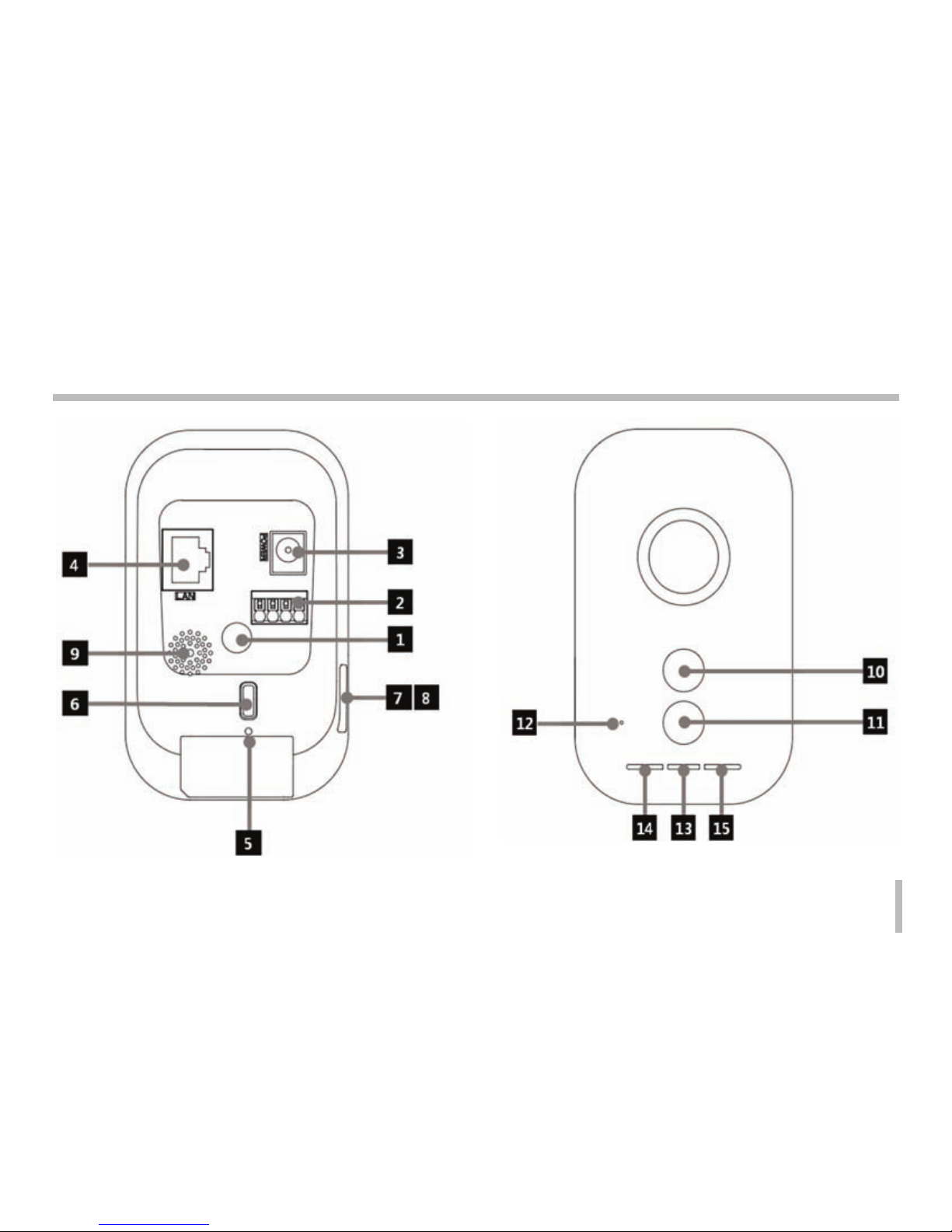
Stand Connecting Hole
You can connect the camera onto a stand using this hole.
I/O Terminals
IN (Sensor Input) Terminal: Connect a sensor here.
OUT (Relay output) Terminal: Connect an alarm (relay)
device here.
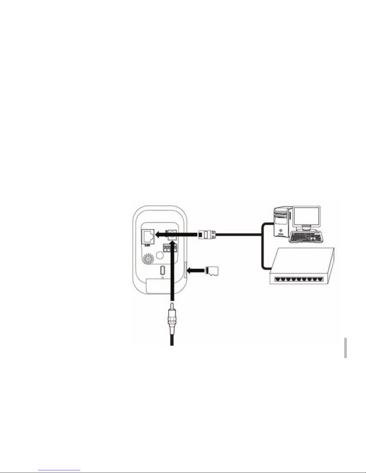
Power Socket
Connect a DC 5V power supply.
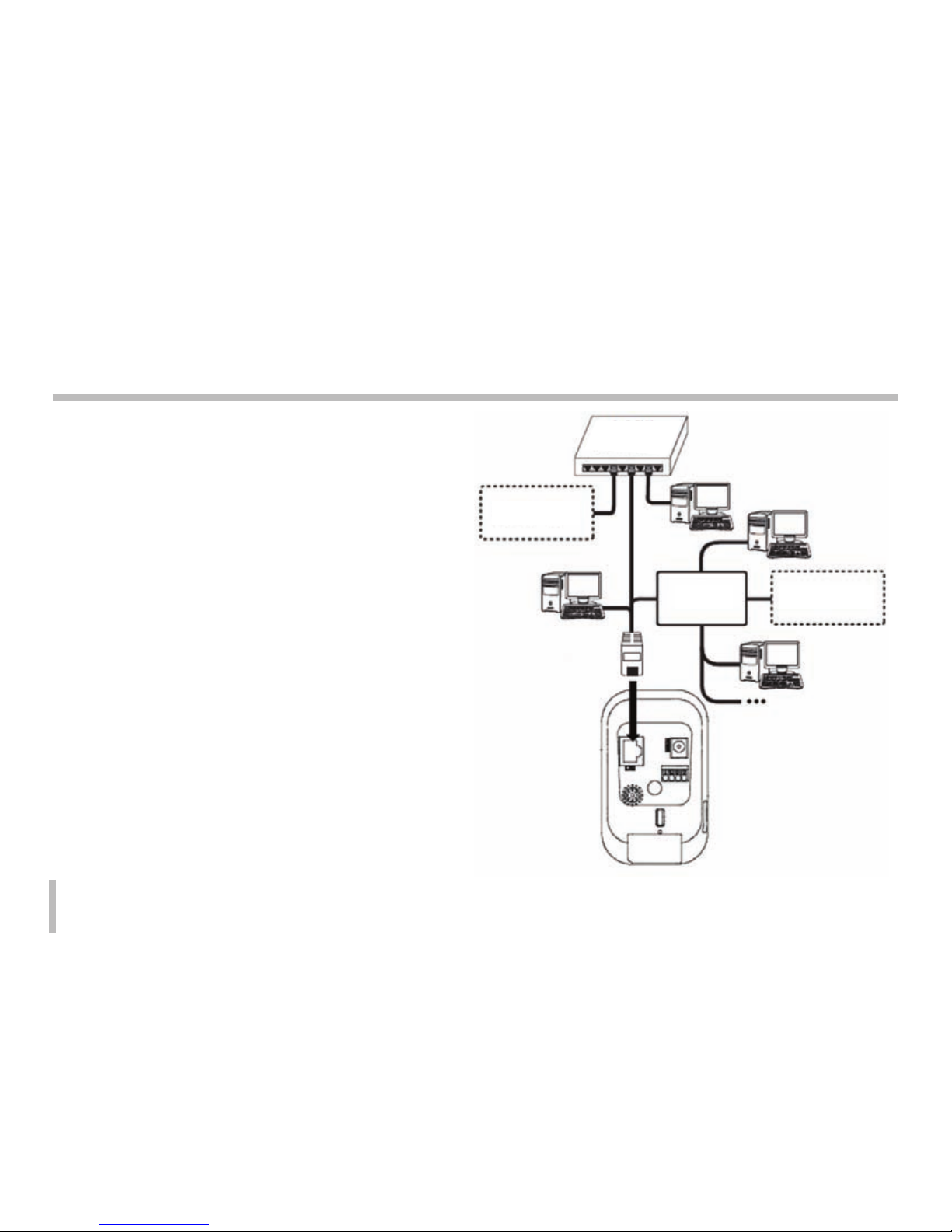
Ethernet Terminal
Use a 10 BASE-T/100 BAST-TX network cable to
connect to a PC or a network hub.
REBOOT
Push this button to restart the device.
WPS, Factory Setting
Press to use WPS or return the device to factory default setting.
Hold the button down for less than 4 seconds to activate
WPS feature.
Hold the button down for longer than 10 seconds to
activate the factory default mode. Once the power lamp
starts to blink in yellow and green, release the button to
run in factory default model.
When a WPS connection is established, the Wireless
Lan Connection lamp will blink in red and green colors.
Once the lamp turns green and stops blinking, the
connection establishment is complete.
Red color of the connection lamp means a connection failure.
1
2
3
4
5
6
micro SD Card Slot Cover
micro SD Card Slot
Insert a micro SD Card here.
Speaker
It delivers the sound from the microphone of the PC to
the camera, to be played by the speaker on the device.
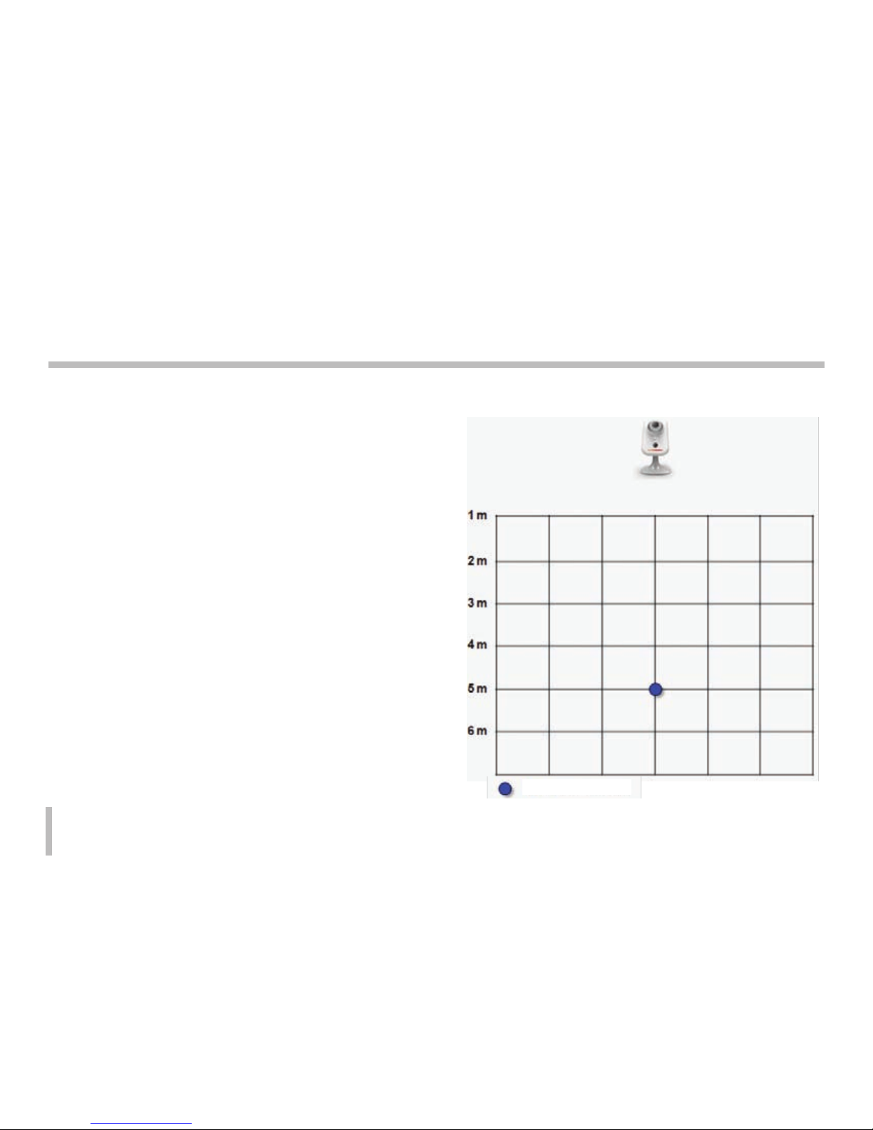
Motion Detector
Detects motions occurring in vicinity of the device.
Flash LED
The LED lamp can be turned on/off through the config
uration mode.
Microphone
The sounds coming from the vicinity of the device is
delivered through this microphone to a connected PC.
Power Lamp
Turns on in green color when the power supply is on
and the device is running.
Ethernet Connection Lamp
Turns on in green color when the ethernet connection
to the network is established.
Wireless Lan Connection Lamp
Green light means that the Wireless LAN connection
is successfully established.
7
8
9
10
11
12
13
14
15
8