LG 62SA1D User manual

LCoS Projection TV
OWNER’S MANUAL
MODELS: 62SA1D/71SA1D
62SA1D-UA/71SA1D-UA
LG Electronics U.S.A., Inc.
TM
R
TruSurround XT
Please read this manual carefully and completely before
operating your TV.
Retain this manual for future reference.
Record model number and serial number of the TV in the
spaces provided below.
See the label attached on the back cover and relate this
information to your dealer if you require service.
Model Number :
Serial Number :

2 LCoS Projection TV
WARNING/CAUTION:
TO REDUCE THE RISK OF ELECTRIC SHOCK DO NOT REMOVE COVER (OR BACK). NO USER
SERVICEABLE PARTS INSIDE. REFER TO QUALIFIED SERVICE PERSONNEL.
The lightning flash with arrowhead symbol, within an equilateral triangle, is intended to alert the user to
the presence of uninsulated “dangerous voltage” within the product’s enclosure that may be of suffi-
cient magnitude to constitute a risk of electric shock to persons.
The exclamation point within an equilateral triangle is intended to alert the user to the presence of
important operating and maintenance (servicing) instructions in the literature accompanying the appli-
ance.
WARNING/CAUTION:
TO PREVENT FIRE OR SHOCK HAZARDS, DO NOT EXPOSE THIS PRODUCT TO RAIN OR MOISTURE.
POWER CORD POLARIZATION:
CAUTION: TO PREVENT ELECTRIC SHOCK, MATCH WIDE BLADE OF PLUG TO WIDE SLOT, FULLY
INSERT.
ATTENTION: POUR ÉVITER LES CHOCS ÉLECTRIQUES, INTRODUIRE LA LAME LA PLUS LARGE
DE LA FICHE DANS LA BORNE CORRESPONDANTE DE LA PRISE ET POUSSER JUSQU’AU FOND.
NOTE TO CABLE/TV INSTALLER:
This reminder is provided to call the CATV system installer’s attention to Article 820-40 of the National
Electric Code (U.S.A.). The code provides guidelines for proper grounding and, in particular, specifies that
the cable ground shall be connected to the grounding system of the building, as close to the point of the
cable entry as practical.
REGULATORY INFORMATION:
This equipment has been tested and found to comply with the limits for a Class B digital device, pursuant to Part
15 of the FCC Rules. These limits are designed to provide reasonable protection against harmful interference in
a residential installation. This equipment generates, uses and can radiate radio frequency energy and, if not
installed and used in accordance with the instructions, may cause harmful interference to radio communications.
However, there is no guarantee that interference will not occur in a particular installation. If this equipment does
cause harmful interference to radio or television reception, which can be determined by turning the equipment off
and on, the user is encouraged to try to correct the interference by one or more of the following measures:
- Reorient or relocate the receiving antenna.
- Increase the separation between the equipment and receiver.
- Connect the equipment into an outlet on a circuit different from that to which the receiver is connected.
- Consult the dealer or an experienced radio/TV technician for help.
Any changes or modifications not expressly approved by the party responsible for compliance could void the
user’s authority to operate the equipment.
CAUTION:
Do not attempt to modify this product in any way without written authorization from LG Electronics. Unauthorized mod-
ification could void the user’s authority to operate this product.
COMPLIANCE:
The responsible party for this product’s compliance is:
LG Electronics U.S.A., Inc
1000 Sylvan Avenue, Englewood Cliffs, NJ 07632
1-800-243-0000
http://www.lgusa.com
WARNING
RISK OF ELECTRIC SHOCK
DO NOT OPEN
/CAUTION
W
Warning/Caution
arning/Caution
Warning/Caution

Owner’s Manual 3
TV Guide On Screen Notices for U.S.A.
Digital Cable Compatibility
This digital television is capable of receiving basic analog, digital basic and digital premium cable television programming by
direct connection to a cable system providing such programming. A security card provided by your cable operator is required
to view encrypted digital programming. Certain advanced interactive digital cable services such as video-on-demand, cable
operator enhanced program (For example, electronic program guide provided by the cable operator), and data enhanced
television service may require the use of a set top box. For more information contact your local cable operator.
In the United States, TV GUIDE and other related marks are registered marks of Gemstar-TV Guide International, Inc. and/or
one of its affiliates. In Canada, TV GUIDE is a registered mark of Transcontinental Inc., and is used under license by
Gemstar-TV Guide International, Inc.
The TV Guide On Screen system is protected by one or more of the following issued United States patents 6,498,895,
6,418,556, 6,331,877; 6,239,794; 6,154,203; 5,940,073; 4,908,713; 4,751,578; 4,706,121.
The TV Guide On Screen system is manufactured under license from Gemstar-TV Guide International, Inc. and/or one of its
affiliates.
Use of the CableCARDTM TradeMark.
“CableCARDTM is a trademark of Cable Television Laboratories, Inc.”
Trademark Notice
Aux Etats-Unis TV GUIDE et d’autres marques relatives sont des marques déposées de Gemstar-TV Guide International,
Inc. et/ou d’une de ses sociétés affiliées. Au Canada TV GUIDE est une marque déposée de Transcontinental Inc., utilisée
sous licence de Gemstar-TV Guide International, Inc.
Le système TV Guide On Screen est fabriqués sous licence de Gemstar-TV Guide International, Inc. et/ou d’une de ses sociétés
affiliées.
Le système TV Guide On Screen est protégés par un ou plusieurs brevets émis aux Etats-Unis, comme le 6,498,895,
6,418,556, 6,331,877; 6,239,794; 6,154,203; 5,940,073; 4,908,713; 4,751,578; 4,706,121.
License Notice
Patent Notice

4 LCoS Projection TV
Safety Instructions
IMPORTANT SAFETY INSTRUCTIONS
Important safety instructions shall be provided with each apparatus. This information shall be given in a separate booklet or
sheet, or be located before any operating instructions in an instruction for installation for use and supplied with the appara-
tus. This information shall be given in a language acceptable to the country where the apparatus is intended to be used. The
important safety instructions shall be entitled “Important Safety Instructions”. The following safety instructions shall be includ-
ed where applicable, and, when used, shall be verbatim as follows. Additional safety information may be included by adding
statements after the end of the following safety instruction list. At the manufacturer’s option, a picture or drawing that illus-
trates the intent of a specific safety instruction may be placed immediately adjacent to that safety instruction :
1. Read these instructions.
2. Keep these instructions.
3. Heed all warnings.
4. Follow all instructions.
5. Do not use this apparatus near water.
6. Clean only with dry cloth.
7. Do not block any ventilation openings. Install in accordance with the manufacturer’s instructions.
8. Do not install near any heat sources such as radiators, heat registers, stoves, or other apparatus (including amplifiers)that
produce heat.
9. Do not defeat the safety purpose of the polarized or grounding-type plug. A polarized plug has two blades with one wider
than the other. A grounding type plug has two blades and a third grounding prong, The wide blade or the third prong are pro-
vided for your safety. If the provided plug does not fit into your outlet, consult an electrician for replacement of the obsolete
outlet.
10. Protect the power cord from being walked on or pinched particularly at plugs, convenience receptacles, and the point
where they exit from the apparatus.
11. Only use attachments/accessories specified by the manufacturer.
12. Use only with the cart, stand, tripod, bracket, or table specified by the manufacturer, or sold with the apparatus. When a
cart is used, use caution when moving the cart/apparatus combination to avoid injury from tip-over.
Safety Instructions
Safety Instructions
PORTABLE CART WARNING

Owner’s Manual 5
Safety Instructions
13. Unplug this apparatus during lightning storms or when unused for long periods of time.
14. Refer all servicing to qualified service personnel. Servicing is required when the apparatus has been damaged
in any way, such as power-supply cord or plug is damaged, liquid has been spilled or objects have fallen into
the apparatus, the apparatus has exposed to rain or moisture, does not operate normally, or has been dropped.
15. CAUTION concerning the Power Cord :
Most appliances recommend they be placed upon a dedicated circuit;
that is, a single outlet circuit which powers only that appliance and has no
additional outlets or branch circuits. Check the specification page of
this owner's manual to be certain.
-This may cause a fire or an electric shock.
Do not overload wall outlets. Overloaded wall outlets, loose or damaged
wall outlets, extension cords, frayed power cords, or damaged or
cracked wire insulation are dangerous. Any of these conditions could
result in electric shock or fire. Periodically examine the cord of your
appliance, and if its appearance indicates damage or deterioration,
unplug it, discontinue use of the appliance, and have the cord replaced
with an exact replacement part by an authorized servicer.
Protect the power cord from physical or mechanical abuse, such as being
twisted, kinked, pinched, closed in a door, or walked upon. Pay
particular attention to plugs, wall outlets, and the point where the
cord exits the appliance.
16. Outdoor Use Marking :
WARNING - To Reduce The Risk Of Fire Or Electric Shock, Do Not Expose This Appliance To Rain Or Moisture.
17. Wet Location :
Apparatus shall not be exposed to dripping or splashing and no objects filled with liquids, such as vases, shall
be placed on the apparatus.

6 LCoS Projection TV
Contents
After reading this manual, keep it handy for future reference.
Warnings/Caution . . . . . . . . . . . . . . . . . . . . . . . . . . . . . . .2
Digital Cable Compatibility . . . . . . . . . . . . . . . . . . . . . . . . .3
Safety Instructions . . . . . . . . . . . . . . . . . . . . . . . . . . . . .4~5
Introduction
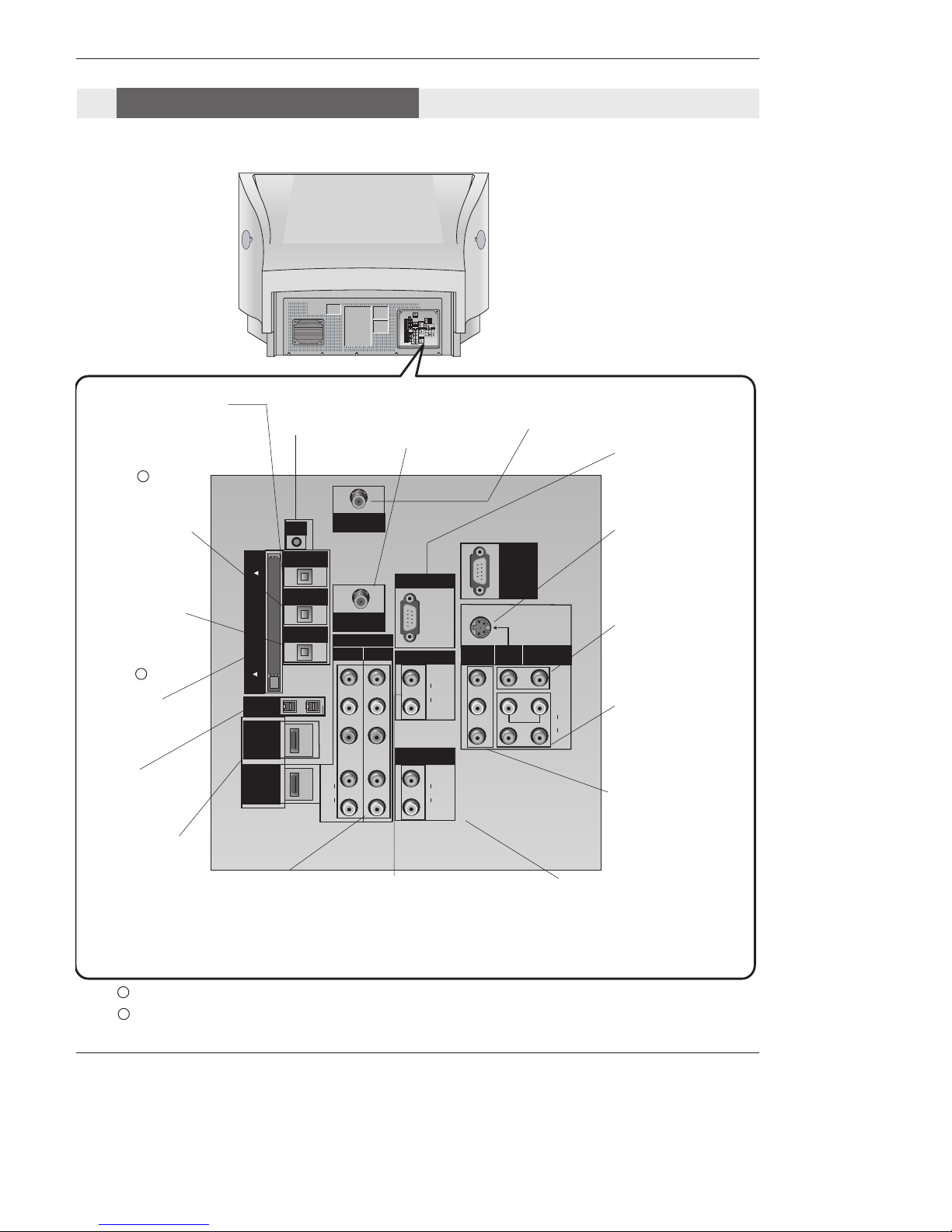
Controls . . . . . . . . . . . . . . . . . . . . . . . . . . . . . . .7
Connection Options . . . . . . . . . . . . . . . . . . . .8~9
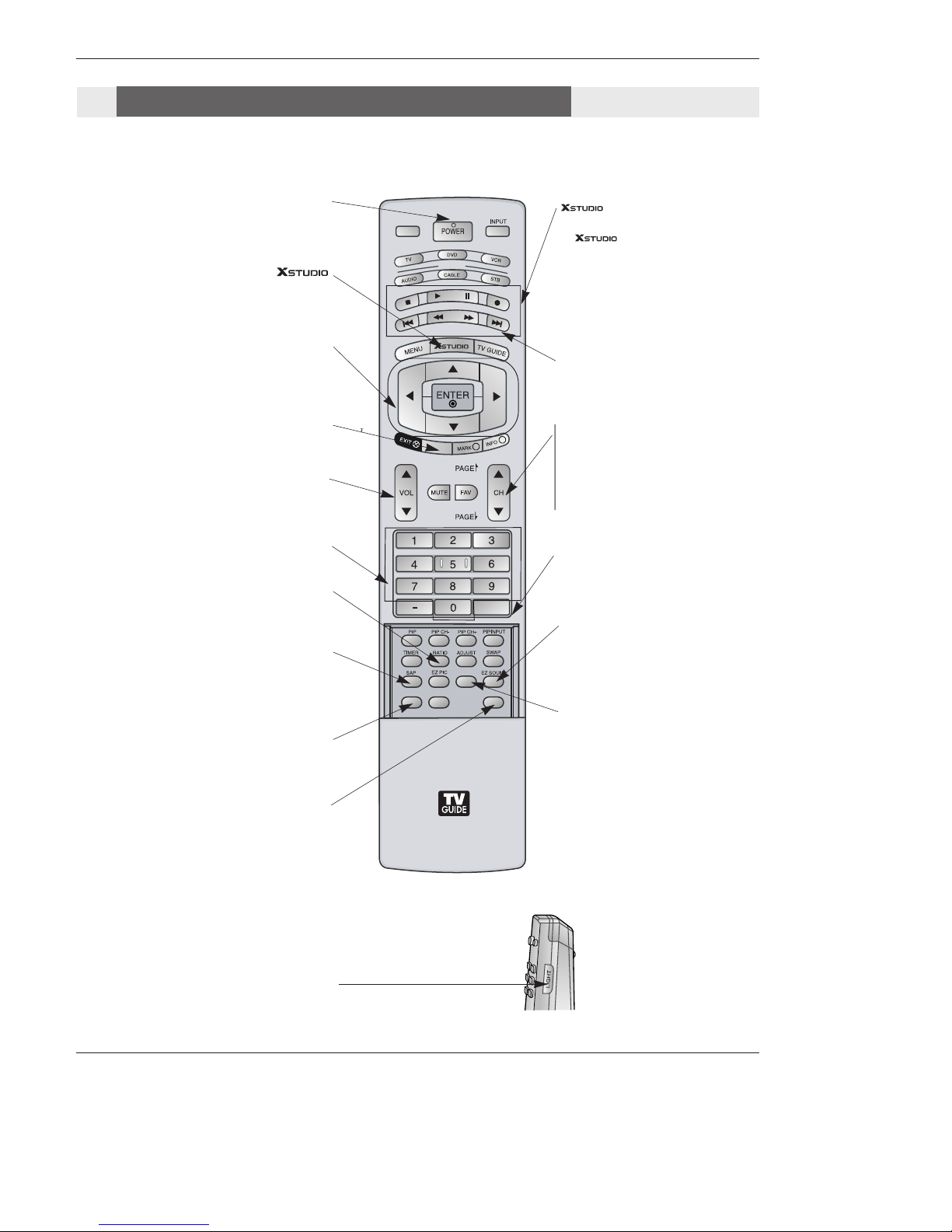
Remote Control Key Functions . . . . . . . . . .10~11
Installation
External Equipment Connections . . . . . . . . . .12~30
Antenna or Cable Connection . . . . . . . . . . . . . .12
VCR Setup . . . . . . . . . . . . . . . . . . . . . . . . . . .13
External A/V Source Setup . . . . . . . . . . . . . . . .14
DVD Setup . . . . . . . . . . . . . . . . . . . . . . . . . . . .14
CableCARDTM Setup . . . . . . . . . . . . . . . . . . . . .15
HDSTB Setup . . . . . . . . . . . . . . . . . . . . . . . . . .15
AV Out Setup . . . . . . . . . . . . . . . . . . . . . . . . . .15
PC Setup . . . . . . . . . . . . . . . . . . . . . . . . . . . . .16
Digital Audio Output . . . . . . . . . . . . . . . . . . . . .17
External Stereo . . . . . . . . . . . . . . . . . . . . . . . . .17
HDMI . . . . . . . . . . . . . . . . . . . . . . . . . . . . .18~20
TV Guide On Screen Setup . . . . . . . . . . . . . .21~30
IEEE 1394 Functions . . . . . . . . . . . . . . . . . . . . . .31-37
TV Guide On ScreenTM System . . . . . . . . . . . . . .38-56
Operation
Turning the TV On . . . . . . . . . . . . . . . . . . . . . .57
TV Setup
On-screen Menus Language Selection . . . . . . .58
Setup Menu Options
EZ Scan (Channel Search) . . . . . . . . . . . . . . . .59
Manual Scan . . . . . . . . . . . . . . . . . . . . . . . . . .59
Channel Edit . . . . . . . . . . . . . . . . . . . . . . . . . . .60
DTV Signal Strength . . . . . . . . . . . . . . . . . . . . .60
Main Picture Source Selection . . . . . . . . . . . . .61
Input Label . . . . . . . . . . . . . . . . . . . . . . . . . . . .61
Video Menu Options
EZ Picture . . . . . . . . . . . . . . . . . . . . . . . . . . . .62
Manual Picture Control (Custom Option) . . . . . .62
Color Temperature Control . . . . . . . . . . . . . . . .62
ACE (Advanced Contrast Enhancement) . . . . . .63
Video Reset . . . . . . . . . . . . . . . . . . . . . . . . . . .63
Audio Menu Options
Audio Language . . . . . . . . . . . . . . . . . . . . . . . .64
EZ SoundRite / EZ Sound . . . . . . . . . . . . . . . . .64
Manual Sound Control (Custom Option) . . . . . .64
Front Surround . . . . . . . . . . . . . . . . . . . . . . . . .65
TV Speakers On/Off Setup . . . . . . . . . . . . . . . .65
Stereo/SAP Broadcasts Setup . . . . . . . . . . . . . .65
Time Menu Options
Auto Clock Setup . . . . . . . . . . . . . . . . . . . . . . .66
Manual Clock Setup . . . . . . . . . . . . . . . . . . . . .66
On/Off Timer Setup . . . . . . . . . . . . . . . . . . . . .66
Sleep Timer / Auto Off . . . . . . . . . . . . . . . . . . . .67
Option Menu Features
Aspect Ratio Control . . . . . . . . . . . . . . . . . . . . .68
Cinema 3:2 Mode Setup . . . . . . . . . . . . . . . . . .68
Caption . . . . . . . . . . . . . . . . . . . . . . . . . . . . . . .69
Caption / Text . . . . . . . . . . . . . . . . . . . . . . . . . .69
Caption Option . . . . . . . . . . . . . . . . . . . . . . . . .70
EZ Demo . . . . . . . . . . . . . . . . . . . . . . . . . . . . .70
Lock Menu Options
Parental Lock Setup . . . . . . . . . . . . . . . . . . . . .72
CableCARDTM Function
Cable menu options . . . . . . . . . . . . . . . . . . . . .73
Scrambled channel . . . . . . . . . . . . . . . . . . . . . .73
Cable Channel List . . . . . . . . . . . . . . . . . . . . . .74
Emergency Alert Message . . . . . . . . . . . . . . . .74
Notes on Memory Card . . . . . . . . . . . . . . . .75~78
JEPG File Viewing Options . . . . . . . . . . . . .79~83
MP3 File Playing Operation . . . . . . . . . . . . .84~87
Remote Control
PIP (Picture-in-Picture)/POP/Twin Picture . . . ..88
Watching PIP/POP/Twin Picture . . . . . . . . . . . ..88
Selecting an Input Signal Source for PIP/Twin Picture
. .88
Swapping the PIP/Twin Picture . . . . . . . . . . . . .88
TV Program Selection for PIP . . . . . . . . . . . . . .88
Moving the PIP sub picture . . . . . . . . . . . . . . . .89
Adjusting Main and Sub Picture Sizes for Twin Picture . .89
POP (Picture-out-of-Picture: Channel Scan) . . .89
APM(Adaptive Picture Mode) . . . . . . . . . . . . . .90
Brief Info.. . . . . . . . . . . . . . . . . . . . . . . . . . . . . .91
Mute . . . . . . . . . . . . . . . . . . . . . . . . . . . . . . . . .92
Freeze & Magnify . . . . . . . . . . . . . . . . . . . . . . .92
Screen Setup for PC mode . . . . . . . . . . . . . . . .93
Programming the Remote . . . . . . . . . . . . . . . . . . . . . .94
Programming Codes . . . . . . . . . . . . . . . . . . . . . . .95~96
Troubleshooting Checklist . . . . . . . . . . . . . . . . . . .97~99
Maintenance . . . . . . . . . . . . . . . . . . . . . . . . . . . . . . . .100
Product Specifications . . . . . . . . . . . . . . . . . . . . . . . .101
Warranty . . . . . . . . . . . . . . . . . . . . . . . . . . . . . . . .103~104
Contents
Contents

Owner’s Manual 7
Introduction
Introduction
Introduction
POWER Button VOLUME
Buttons
CHANNEL Buttons Operation Indicator/
Lamp Indicator/
Temperature Indicator
ENTER Button
TV GUIDE Button
- Lamp indicator, operation indicator, and temperature indicator located below the front panel controls, reveal the
operating status of the LCoS projection TV.
Function Status Indicators
MENU Button
Controls
Controls
Front Panel Controls
On operating the
mode
Off Power Cord is not connected.
Red Power Cord is connected, TV is in standby mode.
Green TV turns on.
Red (blinking) Power Cord is connected, TV is in booting sequence.
White (Stacking) Preparing operation in standby mode.
Orange Projection lamp is reaching the end of its life and needs to
be replaced with a new lamp. Contact your service center.
Red (blinking) There is a problem with the lamp or around it. Contact an
authorized service center.
Green (blinking) The lamp cover is not closed.
Orange The projection TV is overheating. Check the blocked vents
of the Projection TV .
Red The projection TV shuts down due to overheating.
Red (blinking) The projection TV shuts down, check the cooling fan.
Contact your service center.
Operation Indicator
Lamp Indicator
Temperature Indicator
- This is a simplified representation of a front panel.
- Here shown may be somewhat different from your TV.
- This manual explains the features available on the 71SA1D series TVs.
* To high quality of the
sound, do not press the
speakers.

8 LCoS Projection TV
Introduction
XGA/
480p/
720p/
1080i S-VIDEO
PR
PB
Y
(MONO)
CABLE
RGB IN(PC/DTV)
COMPONENT IN
21
AUDIO IN(RGB/DVI)
(L)
(R)
AUDIO
(L)
(R)
AUDIO
VIDEO
(L)
(R)
AUDIO
(L)
(R)
AUDIO
AV OUT AV IN 2 AV IN 1
DIGITAL AUDIO
OPTICAL IN 1
(COMPONENT2)
DIGITAL AUDIO
OPTICAL IN 2
(DVI)
IEEE-1394 IN
DIGITAL AUDIO
OPTICAL OUT
ANTENNA
C
a
b
l
e
C
A
R
D
HDMI IN 1
(DVI)
VARIABLE
AUDIO OUT
G-LINK
HDMI IN 2
SERVICE
ONLY
(XGA/
480p/
720p/
1080i) S-VIDEO
PR
PB
Y
(MONO)
CABLE
RGBIN(PC/DTV)
COMPONENTIN
21
AUDIOIN(RGB/DVI)
(L)
(R)
AUDIO
(L)
(R)
AUDIO
VIDEO
(L)
(R)
AUDIO
(L)
(R)
AUDIO
AVOUT AV2 IN AV1IN
DIGITALAUDIO
OPTICALIN
(COMPONENT)
DIGITALAUDIO
OPTICALIN
(DVI)
IEEE-1394IN
DIGITALAUDIO
OPTICALOUT
ANTENNA
C
a
b
l
e
C
A
R
D
HDMI1 IN
(DVI)
VARIABLE
AUDIOOUT
G-LINK
HDMI2 IN
SERVICE
ONLY
ANTENNA Inputs
Connect antenna sig-
nals to the TV directly.
DIGITAL AUDIO OPTICAL
OUTPUT
Used to connect either an exter-
nal amplifier to your surround
sound system if it has a digital
audio optical input.
(Refer to )
AV OUTPUT
Connect a second TV or
Monitor.
S-VIDEO In
A connection available
with some high-end
equipment that provides
even better picture qual-
ity for AV 2.
AUDIO IN (RGB/DVI )
Connect the monitor
output connector from
a PC to the appropri-
ate input port.
RGB IN(PC/DTV)
Connect the TV output
connector from a PC/DTV
to the appropriate input
port.
VARIABLE AUDIO OUT
Used to connect either
an external amplifier
to your surround sound
system.
COMPONENT IN 1-2
Connect a component
video/audio device to
these jacks. Refer to your
DVD manual for further
information.
VIDEO AV IN 1 or AV IN 2
Connects the video signals
from various types of
equipment.
Left/Right AUDIO
Used for stereo sound
from various types of
equipment.
IEEE-1394 IN
Connect DVHS or
MicroMV to IEEE1394
Connector.
CableCARD™
Used for CableCARD™
received Cable Service
Provider.
CABLE Inputs
Connect cable signals to
the TV, either directly or
through your cable box.
G-LINK
Connect a G-
LINK Cable to
this jack.
DIGITAL AUDIO OPTI-
CAL IN 1 (COMPO-
NENT2)
Connect digital audio
from the equipment
connected to COMPO-
NENT 2.
DIGITAL AUDIO OPTI-
CAL IN 2 (DVI)
Connect digital audio
from the equipment
connected to
HDMI/DVI(VIDEO).
(Refer to )
Notes: In standby mode, these port will not work.
If the video is connected through HDMI-TO-HDMI cable, you don’t need to connect digital audio. This port
is used only when the video connected through DVI-TO-HDMI cable.
1
2
1
2
HDMI IN 1(DVI), HDMI
IN 2
Connect a HDMI signal
to HDMI1/DVI or
HDMI2. Or connect a
DVI(Video) signal to
HDMI1/DVI.
Back Connection Panel
Connection Options
Connection Options

Owner’s Manual 9
Introduction
LEFT/RIGHT
AUDIO
Used for stereo
sound from vari-
ous types of
equipment.
S-VIDEO
A connection available
on some very high-end
equipment that pro-
vides better picture
quality than video input.
VIDEO
Connects the
video signals
from any piece of
equipment.
AV IN 3V IN 3
AV IN 3
There are four jacks on the left side on your projection TV
that make connecting Audio/Video devices like video
games and camcorders very simple.
The jacks are like those found on the back jack connec-
tion panel. This means that most equipment that connects
to those types of jacks on the rear jackpack, may be con-
nected to the front connection panel.
To use the side jacks as the signal source, select them
using Main Input menu as described on page 61. They
will be named “AV IN 3”in the Main Input menu.
If you input both AV IN 3 and S-
Video, only the S-Video will work.
If you’re connecting a video game
device, make sure to change the
picture settings with the EZ
Picture option in the Video menu
(see page 62).
Mini glossary
A/V CABLESAudio/Video cables. Three cable connector—Right audio (red), Left audio (white), and Video (yellow). A/V cables are
used for stereo playback of videocassettes and for higher quality picture and sound from other A/V devices.
A/V DEVICE Any device that produces video or sound (VCR, DVD, cable box, or television).
Front Connection Panel

Introduction
10 LCoS Projection TV
MODE
DAY -
DAY +
FLASHBK
i
APM
CC
FREEZE
M/C EJECT
TV INPUT
V
1394
- When using the remote control, aim it at the remote control sensor on the TV.
Remote Control Key Functions
LIGHT
Illuminates the remote control
buttons of selected
mode.
DAY+/DAY-
Moves forward or backward in 24
hour increments in the Listings Grid.
NUMBER buttons
RATIO
Changes the aspect ratio.
POWER
Turns your TV or any other programmed
equipment on or off, depending on mode.
CC
Select a closed caption:
Off, CC1~4, Text1~4.
THUMBSTICK (Up/Down/Left/Right/ENTER)
Allows you to navigate the on-screen menus
and adjust the system settings to your pref-
erence.
CHANNEL UP/DOWN
Selects available channels found dur-
ing EZ scan.
PAGE UP/ DOWN
Moves from one full set of screen
information to the next one.
SAP
Selects MTS sound: Mono, Stereo, and SAP
in Analog mode. Change the audio language
in DTV mode.
EZ SOUND
Selects the sound appropriate for the
program's character.
Brings up the menu to select the Photo or
Music mode of Xstudio for memory cards.
APM(Adaptive Picture Mode)
Concurrently, compare with the
Daylight, Normal, Night Time.and
Custom on the screen.
VOLUME UP/DOWN
Increases/decreases the sound level.
1394 (Refer to p. 31-37)
M/C EJECT
Remove the Memory Card.
FLASHBK
Tunes to the last channel viewed.
/VCR/DVD control buttons
•Use for Photo mode or Music mode
of .(Refer to p.81~ 85)
•Controls the DVHS or Camcorder in
•IEEE 1394 mode.
•Controls some video cassette ••••
•recorders or DVD players when you
•have already selected DVD or VCR
•mode button.

Owner’s Manual 11
Introduction
•Open the battery compartment cover on the back side and install the batteries
matching correct polarity (+ with +, - with -).
•Install two 1.5V AA batteries. Don’t mix old or used batteries with new ones.
Close cover.
Installing Batteries
MODE
DAY -
DAY +
FLASHBK
i
APM
CC
FREEZE
M/C EJECT
TV INPUT
V
1394
TV INPUT
•Rotates the input mode between Antenna
and Cable.
•AV 1-2, AV3, Component 1-2, RGB-DTV
(or RGB-PC), HDMI1/DVI, HDMI2
and IEEE1394 input sources, TV will return
to the last TV channel.
MUTE
Switches the sound on or off.
(Refer to p.92)
MODE
Selects the remote operating mode: TV,
DVD, VCR, AUDIO, CABLE or STB. Select
other operating modes, for the remote to
operate external devices.
EXIT
Clears all on-screen displays and returns to
TV viewing from any menu.
TIMER
Lets you select the amount of time before
your TV turns itself off automatically.
MENU
Brings up the main menu to the screen.
Enters or exits a Panel Menu in the TV Guide
On Screen system.
PIP
Switches to PIP, POP (Picture-out-of-
Picture) and Twin picture modes in regu-
lar sequence.
Switches the video window locking or
unlocking in the Listings Grid.
PIPCH-/PIPCH+
Changes to the next higher/lower PIP
channel.
PIP INPUT
Selects the input source for the sub pic-
ture in PIP/Twin picture mode.
SWAP
Exchanges the main/sub images in
PIP/Twin picture mode.
EZ PIC
Adjusts the factory preset picture
depending on the viewing environment.
ADJUST
Adjusts screen position, size, and phase in
PC mode.
FREEZE
Freezes the currently-viewed picture.
Main picture is frozen in PIP/Twin picture
mode.
INPUT
External input modes rotate in regular
sequence: Antenna, Cable, AV1-2, AV3,
Component 1-2, RGB-DTV (or RGB-PC),
HDMI1/DVI and HDMI2 input sources.
(AV1-2, AV3, Component 1-2 input
sources are linked automatically, only if
these are connected )
INFO
When you watch the TV, information dis-
plays on top of the screen. Not available
in Component 1-2, RGB, HDMI1/DVI and
HDMI2 mode.(Refer to p.91)
FAV
Scrolls the Favorite channels.
TV GUIDE
Brings up the TV Guide On Screen sys-
tem to the screen.
MARK
Selects the wanted functions.

12 LCoS Projection TV
Installation
- Wall Antenna Socket or Outdoor Antenna without a Cable Box Connections
- For optimum picture quality, adjust antenna direction if needed.
Antenna or Cable Connection
1. Analog and Digital TV signals provided on antenna
2. Analog and Digital TV signals provided on cable
ANTENNA
Multi-family Dwellings/Apartments
(Connect to wall antenna socket)
Single-family Dwellings /Houses
(Connect to wall jack for outdoor antenna)
Outdoor
Antenna
Wall Antenna
Socket
VHF Antenna
UHF Antenna
RF Coaxial Wire (75 ohm)
Bronze Wire
Turn clockwise to tighten.
Bronze Wire
Be careful not to bend the bronze wire when
connecting the antenna.
Bronze Wire
Cable TV Wall
Jack RF Coaxial Wire (75 ohm)
CABLE
Installation
Installation
External Equipment Connections
Turn clockwise to tighten.

Owner’s Manual 13
Note: The TV will let you know when the TV(analog antenna), DTV(digital antenna), CATV(analog cable) and CADTV(digital
cable) channel scans are complete.
•To improve the picture quality in a poor signal area,
please purchase a signal amplifier and install properly.
•If the antenna needs to be split for two TV’s, install a “2-
Way Signal Splitter”in the connections.
•If the antenna is not installed properly, contact your deal-
er for assistance.
ANTENNA
Signal
Amplifier
3. Analog and Digital TV signals provided on cable and antenna
Antenna
RF Coaxial Wire (75 ohm)
Bronze Wire
Turn clockwise to tighten.
Cable TV Wall
Jack RF Coaxial Wire (75 ohm)
CABLE
ANTENNA
Connection Option 1
Set VCR output switch to channel 3 or 4 and then tune the
TV to the same channel number.
Connection Option 2
1. Connect the audio and video cables from the VCR's output
jacks to the TV input jacks, as shown in the figure.
When connecting the TV to VCR, match the jack colors
(Video = yellow, Audio Left = white, and Audio Right = red).
If you connect an S-VIDEO output from VCR to the S-VIDEO
input, the picture quality is improved; compared to connecting
only the Video input.
2. Insert a video tape into the VCR and press PLAY on the
VCR. (Refer to the VCR owner’s manual.)
3. Select the input source with using the INPUT button on the
remote control. Note that this TV finds the connected input
sources automatically for AV1-2, AV3 and Component 1-2. It
is presumed that RGB, HDMI1/DVI and HDMI2 sources are
connected.
Do not connect to both Video and S-Video at the
same time. In the event that you connect both Video
and the S-Video cables, only the S-Video will work.)
VCR Setup
VCR Setup
S-VIDEO OUT
IN
(R) AUDIO (L)VIDEO
34
OUTPUT
SWITCH
ANT OUT
ANT IN
XGA/
480p/
720p/
1080i S-VIDEO
PR
PB
Y
(MONO)
CABLE
RGB IN(PC/DTV)
COMPONENT IN
21
AUDIO IN(RGB/DVI)
(L)
(R)
AUDIO
(L)
(R)
AUDIO
VIDEO
(L)
(R)
AUDIO
(L)
(R)
AUDIO
AV OUT AV IN 2 AV IN 1
DIGITAL AUDIO
OPTICAL IN 1
(COMPONENT2)
DIGITAL AUDIO
OPTICAL IN 2
(DVI)
IEEE-1394 IN
DIGITAL AUDIO
OPTICAL OUT
ANTENNA
C
a
b
l
e
C
A
R
D
HDMI IN 1
(DVI)
VARIABLE
AUDIO OUT
G-LINK
HDMI IN 2
SERVICE
ONLY
VCR Rear
12
Installation
Bronze Wire

14 LCoS Projection TV
Installation
•Component Input ports
To get better picture quality, connect a DVD player to the
component input ports as shown below.
Component ports
on the TV Y PBPR
Video output ports
on DVD player
Y
Y
Y
Y
Pb
B-Y
Cb
PB
Pr
R-Y
Cr
PR
How to connect
1. Connect the DVD video outputs (Y, PB, PR) to the COMPO-
NENT (Y, PB, PR) INPUT jacks on the TV and connect the
DVD audio outputs to the AUDIO IN jacks on the TV, as shown
in the figure.
2. If your DVD only has an S-Video output jack, connect this to
the S-VIDEO input on the TV and connect the DVD audio out-
puts to the AUDIO IN jacks on the TV, as shown in the figure.
Note: If your DVD player does not have component video output,
use S-Video.
How to use
1. Turn on the DVD player, insert a DVD.
2. Use the INPUT button on the remote control to select
Component 1 or Component 2. (If connected to S-VIDEO,
select the AV1 or AV3 external input source.)
3. Refer to the DVD player's manual for operating instructions.
DVD Setup
DVD Setup
(R) AUDIO (L)
S-VIDEO
BR
(R) AUDIO (L) DIGITAL AUDIO
OPTICAL
XGA/
480p/
720p/
1080i S-VIDEO
PR
PB
Y
(MONO)
CABLE
RGB IN(PC/DTV)
COMPONENT IN
21
AUDIO IN(RGB/DVI)
(L)
(R)
AUDIO
(L)
(R)
AUDIO
VIDEO
(L)
(R)
AUDIO
(L)
(R)
AUDIO
AV OUT AV IN 2 AV IN 1
DIGITAL AUDIO
OPTICAL IN 1
(COMPONENT2)
DIGITAL AUDIO
OPTICAL IN 2
(DVI)
IEEE-1394 IN
DIGITAL AUDIO
OPTICAL OUT
ANTENNA
C
a
b
l
e
C
A
R
D
HDMI IN 1
(DVI)
VARIABLE
AUDIO OUT
G-LINK
HDMI IN 2
SERVICE
ONLY
DVD
Notes:
• Digital Audio will not work for Component 1 input source.
• Digital Audio operation has priority if Digital Audio and AUDIO L/R
are connected at the same time.
or
How to connect
Connect the audio and video cables from the external equip-
ment's output jacks to the TV input jacks, as shown in the
figure.
When connecting the TV to external equipment, match the
jack colors (Video = yellow, Audio Left = white, and Audio
Right = red).
How to use
1. Select the input source by using the INPUT button on the
remote control. Note that this TV finds the connected input
sources automatically for AV 1-2 and Component 1-2. It is
presumed that RGB, HDMI1/DVI and HDMI2 sources are
connected.
2. Operate the corresponding external equipment. For connec-
tion instructions for operating the TV Guide On Screen sys-
tem, see page 21~22.
External
External A/V Source Setup
A/V Source Setup
(L)
(R)
RL
AUDIO VIDEO
XGA/
480p/
720p/
1080i S-VIDEO
(MONO)
RGB IN(PC/DTV)
AUDIO IN(RGB/DVI)
(L)
(R)
AUDIO
(L)
(R)
AUDIO
VIDEO
(L)
(R)
AUDIO
AV OUT AV IN 2 AV IN 1
VARIABLE
AUDIO OUT
SERVICE
ONLY
AUDIO
VIDEO
Camcorder
Video Game
Set

Owner’s Manual 15
Installation
The TV has a special signal output capability which allows you to
hook up a second TV or monitor.
Connect the second TV or monitor to the TV’s AV OUT. See the
Operating Manual of the second TV or monitor for further details
regarding that device’s input settings.
Note
• Component, RGB-PC/RGB-DTV, HDMI1/DVI,HDMI2, DTV input
sources cannot be used for AV out.
A
AV Out Setup
V Out Setup
IN
(R) AUDIO (L) VIDEO
S-VIDEO
XGA/
480p/
720p/
1080i S-VIDEO
(MONO)
RGB IN(PC/DTV)
AUDIO IN(RGB/DVI)
(L)
(R)
AUDIO
(L)
(R)
AUDIO
VIDEO
(L)
(R)
AUDIO
AV OUT AV IN 2 AV IN 1
VARIABLE
AUDIO OUT
SERVICE
ONLY
How to connect
Use the TV’s COMPONENT (Y, PB, PR) INPUT, RGB, HDMI1/DVI or
HDMI2 jack for video connections, depending on your set-top box connec-
tor. Then, make the corresponding audio connections.
Note: HDMI(High Definition Multimedia Interface): Input that accepts uncom-
pressed digital signal and multi channel digital audio signal.
How to use
1. Turn on the digital set-top box. (Refer to the owner’s manual for the digital
set-top box.)
2. Use INPUT on the remote control to select Component 1, Component 2,
RGB-DTV, HDMI1/DVI or HDMI2 source.
HDSTB Setup
HDSTB Setup
- This TV can receive Digital Over-the-air/Cable signals without an external digital set-top box. However, if you do receive Digital
signals from a digital set-top box or other digital external device, refer to the figure as shown below.
- This TV supports HDCP (High-bandwidth Digital Contents Protection) protocol for Digital Contents (480p,720p,1080i).
Signal
480i
480p
720p
1080i
Component 1/2
Yes
Yes
Yes
Yes
RGB-DTV,HDMI1/DVI,HDMI2
No
Yes
Yes
Yes
CableCARD
CableCARDTM
TM Setup
Setup
DIGITAL AUDIO
OPTICAL IN 1
(COMPONENT2)
sDIGITAL AUDIO
OPTICAL IN 2
(DVI)
DIGITAL AUDIO
OPTICAL OUT
C
a
b
l
e
C
A
R
D
G-LINK
How to use
Insert the CableCARDTM
TM received from the cable service provider to the
CableCARDTM
TM slot of TV back panel.
If the pairing information about this TV and the CableCARD is automatically
displayed on the screen, contact with the cable service provider by phone.
Note :
• CableCARDTM
TM have the types of Motorola, Scientific Atlanta, SCM etc..
These 3 types of CableCARDTM
TM can be used for this LCoS Projection TV.
Caution: When removing the CableCARDTM
TM, do not
drop it as this may cause damage to the
CableCARDTM
TM.

16 LCoS Projection TV
Installation
<When the PC supports DVI>
How to connect
1. Connect the PC to HDMI1/DVI port of this TV with an HDMI-to-DVI cable(not supplied with this product).
If you do not need to connect audio, HDMI2 port is also available for the DVI video connection.
2. If the PC(or the sound card of the PC) has a fiber optic digital audio output connector, connect the PC's audio output to DIGI-
TAL AUDIO(OPTICAL) port for DVI INPUT.
3. If the PC(or the sound card of the PC) has an analog audio output connector, connect the PC's audio output to AUDIO INPUT
port located on the right side of RGB INPUT port.
How To Use
1. To get the best picture quality, adjust the PC graphics card to 1024x768, 60Hz.
2. Select HDMI1/DVI input source in main input option of SETUP menu.(Refer to P.61)
INPUT button is also available for this purpose.
3. Check the image on your TV. There may be noise associated with the resolution, vertical pattern, contrast or brightness in PC
mode. If noise is present, change the PC output to another resolution, change the refresh rate to another rate or adjust the
brightness and contrast on the VIDEO menu until the picture is clear. If the refresh rate of the PC graphic card can not be
changed, change the PC graphic card or consult the manufacturer of the PC graphic card.
<When the PC supports RGB>
How to connect
1. Connect the PC to RGB INPUT port of this TV with a RGB cable(supplied with this product).
2. If the PC(or the sound card of the PC) has an analog audio output connector, connect the PC's audio output to AUDIO INPUT
port located on the right side of RGB INPUT port.
How To Use
1. To get the best picture quality, adjust the PC graphics card to 1024x768, 60 Hz.
2. Select RGB-PC input source in main input option of SETUP menu.(Refer to P.61)
Once you select RGB-PC in main input option of SETUP menu, INPUT button is also available for this purpose.
3. Check the image on your TV. There may be noise associated with the resolution, vertical pattern, contrast or brightness in PC
mode. If noise is present, change the PC output to another resolution, change the refresh rate to another rate or adjust the
brightness and contrast on the VIDEO menu until the picture is clear. If the refresh rate of the PC graphic card can not be
changed, change the PC graphic card or consult the manufacturer of the PC graphic card.
PC Setup
PC Setup
- This TV provides Plug and Play capability, meaning that the PC adjusts automatically to the TV's settings.
- The TV perceives 640x480, 60Hz as DTV 480p based on the PC graphic card, change the screen scanning rate for the graphic
card accordingly.
Resolution
640x350
640x480
800x600
Horizontal
Frequency(KHz)
31.468
31.469
37.861
37.500
70.09
59.94
72.80
75.00
48.363
56.476
60.023
Vertical
Frequency(Hz)
1024x768
Monitor Display Specifications (RGB-PC or HDMI/DVI Mode)
35.156
37.879
48.077
46.875
56.25
60.31
72.18
75.00
60.00
70.06
75.02

Owner’s Manual 17
Installation
Send the TV’s audio to external audio equipment (stereo system) via
the Digital Audio Output (Optical) port.
How to connect
1. Connect one end of an optical cable to the TV Digital Audio
(Optical) Out port.
2. Connect the other end of the optical cable to the digital audio (opti-
cal) input on the audio equipment.
3. Set the “TV Speaker option - Off”in the AUDIO menu. Refer to
page 64.
See the external audio equipment instruction manual for operation.
Caution: Do not look into the optical output port. Looking
at the laser beam may damage your vision.
Digital
Digital Audio Output
Audio Output
C
A
B
L
E
C
A
R
D
DVI
HDMI
PR
PB
Y
CABLE
COMPONENT IN
21
(L)
(R)
AUDIO
DIGITAL AUDIO
OPTICAL IN 1
(COMPONENT2)
DIGITAL AUDIO
OPTICAL IN 2
(DVI)
IEEE-1394 IN
DIGITAL AUDIO
OPTICAL OUT
ANTENNA
C
a
b
l
e
C
A
R
D
HDMI IN 1
(DVI)
G-LINK
HDMI IN 2
Hook up Variable Audio Output, L-Audio-R to Amplifier system for
Left/Right front speaker sound.
How to connect
1. Locate the Variable Audio Out jacks on the back of your TV and the
Input jacks on the back of your stereo's amplifier.
2. Connect the two jacks, making sure that the right and left channels
are connected correctly.
3. Set up your speakers through your analog stereo amplifier, accord-
ing to the instructions provided with the amplifier.
External Stereo
External Stereo
XGA/
480p/
720p/
1080i S-VIDEO
(MONO)
RGB IN(PC/DTV)
AUDIO IN(RGB/DVI)
(L)
(R)
AUDIO
(L)
(R)
AUDIO
VIDEO
(L)
(R)
AUDIO
AV OUT AV IN 2 AV IN 1
VARIABLE
AUDIO OUT
SERVICE
ONLY

18 LCoS Projection TV
Installation
- HDMITM, the HDMI logo and High-Definition Multimedia Interface is a trademark or registered trademark of HDMI Licensing.
- This TV can receive the High-Definition Multimedia Interface(HDMI) or the Digital Visual Interface(DVI).
- This TV supports HDCP(High-bandwidth Digital Contents Protection) Protocol for 720x480p, 1280x720p, and 1920x1080i resolu-
tion.
- When you connect this TV with a source device(DVD player, Set Top Box or PC) supporting Auto HDMI/DVI function, the output
resolution of the source device will be automatically set to 1280x720p.
- If the source device does not support Auto HDMI/DVI, you need to set the output resolution appropriately.
To get the best picture quality, adjust the DVD Player or Set Top Box's output resolution to 1280x720p, and the PC graphics card's
output resolution to 1024x768, 60Hz.
- If the source device has an HDMI output, no other audio connection is necessary because HDMI-to-HDMI connection includes
both video and audio.
- If the source device has a DVI output and no HDMI output, a separated audio connection is necessary.
<When the source device(DVD player or Set Top Box) supports HDMI>
How To Connect
1. Connect the source device to HDMI1/DVI or HDMI2 port of this TV with an HDMI cable(not supplied with this product).
2. No separated audio connection is necessary.
How To Use
- If the source device supports Auto HDMI function, the output resolution of the source device will be automatically set to 1920x1080i.
- If the source device does not support Auto HDMI, you need to set the output resolution appropriately.
To get the best picture quality, adjust the output resolution of the source device to 1920x1080i.
- Select HDMI1/DVI or HDMI2 input source in main input option on the SETUP menu.(Refer to P.61)
INPUT button is also available for this purpose.
<When the source device(DVD player or Set Top Box) supports DVI>
How To Connect
1. Connect the source device to HDMI1/DVI port of this TV with a HDMI-to-DVI cable(not supplied with this product).
Do not use HDMI2 port for DVI connection if you want to connect audio.
2. A separated audio connection is necessary.
3. If the source device has a fiber optic digital audio output, connect the audio output to DIGITAL AUDIO(OPTICAL) port for DVI
INPUT.
4. , connect the PC's audio output to AUDIO INPUT port located on the right side of RGB INPUT port.
How To Use
- If the source device supports Auto DVI function, the output resolution of the source device will be automatically set to 1920x1080i.
- If the source device does not support Auto DVI, you need to set the output resolution appropriately.
To get the best picture quality, adjust the output resolution of the source device to 1280x720p.
- Select HDMI1/DVI input source in main input option on the SETUP menu.(Refer to P.61)
INPUT button is also available for this purpose.
HDMI
HDMI

Owner’s Manual 19
Installation
Cable sample
HDMI Cable
(not supplied with the product)
HDMI to DVI Cable
(not supplied with the product)
Fiber Optic Digital Audio Cable
(not supplied with the product)
Analog Audio Cable(RCA type)
(not supplied with the product)
Analog Audio Cable(Stereo to RCA type)
(not supplied with the product)
Reference
Reference

20 LCoS Projection TV
Installation
How to use
1. Connect the HDMI1/DVI Source Devices(DVD Player or Set Top Box or PC) and the TV SET.
2. Turn on the display by pressing the POWER button on the TV SET and HDMI1/DVI Source Devices remote control.
3. Select HDMI1/DVI Input source in Main Input option on the SETUP menu.(Refer to P.61)
4. Check the image on your TV SET. There may be noise associated with the resolution, vertical pattern, contrast or brightness in
HDMI1/DVI Source Devices. If noise is present, change the HDMI1/DVI Source Devices to another resolution, change the
refresh rate or adjust the brightness and contrast on the menu until the picture is clear. If the refresh rate of the PC graphics
card can not changed, change the PC graphics card or consult the manufacturer of the PC graphics card.
Notes:
- Depending on the graphics card, DOS mode may not work if a HDMI to DVI Cable is in use.
- Avoid keeping a fixed image on the screen for a long period of time. The fixed image may become permanently imprinted on the
screen.
- When Source Devices connected with HDMI1/DVI Input, output PC Resolution(VGA, SVGA, XGA), Position and Size may not fit
to Screen. As shown the picture below, press the ADJUST button to adjust the screen Position of TV SET and contact an PC
graphics card service center.
- When Source Devices connected with HDMI1/DVI Input, output TV SET Resolution(480p, 720p, 1080i) and TV SET Display fit
EIA/CEA-861-B Specification to Screen. If not, refer to the Manual of HDMI1/DVI Source Devices or contact your service cen-
ter.
- In case HDMI1/DVI Source Devices is not connected Cable or poor cable connection, "NO SIGNAL" OSD display in HDMI1/DVI
Input. In case that Video Resolution is not supported TV SET output in HDMI1/DVI Source Devices, "INVALID FORMAT" OSD
display. Refer to the Manual of HDMI1/DVI Source Devices or contact your service center.
In This Mode, the Supported TV Set Resolution Specification
- 1920 x 1080 I @ 59.94Hz / 60Hz, 16:9
- 1280 x 720 P @ 59.94Hz / 60Hz, 16:9(preferred format)
- 720 x 480 P @ 59.94Hz / 60Hz, 16:9
- 720 x 480 P @ 59.94Hz / 60Hz, 4:3
In This Mode, the Supported PC Resolution Specification
- 640 x 350 @ 70Hz
- 640 x 480 @ 60Hz
- 640 x 480 @ 72Hz
- 640 x 480 @ 75Hz
- 800 x 600 @ 56Hz
- 800 x 600 @ 60Hz
- 800 x 600 @ 72Hz
- 800 x 600 @ 75Hz
- 1024 x 768 @ 60Hz(preferred format)
- 1024 x 768 @ 70Hz
- 1024 x 768 @ 75Hz
Close
POSITION GG
SIZE
PHASE
RESET
Adjust
DD
FFGG
EE
PC mode
This manual suits for next models
3
Table of contents
Other LG TV manuals