LG Zenith H20J54DT Operating and maintenance manual

Installation Guide & Warranty
Model Number | H20J54DT HealthViewTM TV
© Copyright 2007, LG Electronics U.S.A., Inc.
Zenith and the lightning Z logo are registered
trademarks of Zenith Electronics Corporation
Table of Contents see page
Master TV Setup see page
5
7

Page 2
WARNING: TO REDUCE THE RISK OF ELECTRIC SHOCK DO NOT REMOVE COVER (OR BACK). NO USER
SERVICEABLE PARTS INSIDE. REFER TO QUALIFIED SERVICE PERSONNEL
The lightning flash with arrowhead symbol, within an equilateral triangle, is intended to alert
the user to the presence of uninsulated “dangerous voltage” within the product’s enclosure
that may be of sufficient magnitude to constitute a risk of electric shock to persons.
The exclamation point within an equilateral triangle is intended to alert the user to the pres-
ence of important operating and maintenance (servicing) instructions in the literature accom-
panying the appliance
WARNING:
TO PREVENT FIRE OR SHOCK HAZARDS, DO NOT EXPOSE THIS PRODUCT TO RAIN OR MOISTURE.
POWER CORD POLARIZATION:
This product is equipped with a 3-wire grounding-type alternating current line plug. This plug will fit into
the power outlet only one way. This is a safety feature. If you are unable to insert the plug fully into the
outlet, contact your electrician to replace your obsolete outlet. Do not defeat the safety purpose of the
three-wire ground type plug.
NOTE TO CABLE/TV INSTALLER:
This reminder is provided to call the cable TV system installer’s attention to Article 820-40 of the National
Electric Code (U.S.A.). The code provides guidelines for proper grounding and, in particular, specifies that the
cable ground shall be connected to the grounding system of the building, as close to the point of the cable
entry as practical.
REGULATORY INFORMATION:
This equipment has been tested and found to comply with the limits for a Class B digital device, pursuant to
Part 15 of the FCC Rules. These limits are designed to provide reasonable protection against harmful interfer-
ence when the equipment is operated in a residential installation. This equipment generates, uses and can
radiate radio frequency energy and, if not installed and used in accordance with the instruction manual, may
cause harmful interference to radio communications. However, there is no guarantee that interference will not
occur in a particular installation. If this equipment does cause harmful interference to radio or television
reception, which can be determined by turning the equipment off and on, the user is encouraged to try to
correct the interference by one or more of the following measures:
• Reorient or relocate the receiving antenna.
• Increase the separation between the equipment and receiver.
• Connect the equipment into an outlet on a circuit different from that to which the receiver is connected.
• Consult the dealer or an experienced radio/TV technician for help.
CAUTION:
Do not attempt to modify this product in any way without written authorization from LG Electronics
U.S.A., Inc. Unauthorized modification could void the user’s authority to operate this product.
COMPLIANCE:
The responsible party for this product’s compliance is: LG Electronics U.S.A., Inc.
1000 Sylvan Avenue, Englewood Cliffs, NJ 07632, USA • Phone: 1-201-816-2000.
WARNING
RISK OF ELECTRIC SHOCK
DO NOT OPEN
For Customer Support/Service, please call:
1-888-865-3026
www.lgcommercial.com • www.zenith.com
Marketed and Distributed in the United States by LG Electronics U.S.A., Inc.
2000 Millbrook Drive, Lincolnshire, IL 60069
HealthViewTM is a registered trademark of Zenith Electronics Corporation
©Copyright 2007, LG Electronics U.S.A., Inc.
RECORD THE H20J54DT SERIAL NUMBER
The serial number of the HealthViewTMTV is located
on the back of the cabinet. For future reference, we
suggest that you record the number here:
Serial No.___________________________________

Page 3
SAFETY INSTRUCTIONS
Important safety instructions shall be provided with each apparatus. This informa-
tion shall be given in a separate booklet or sheet, or be located before any operat-
ing instructions in an instruction for installation for use and supplied with the
apparatus.
This information shall be given in a language acceptable to the country where the
apparatus is intended to be used.
The important safety instructions shall be entitled “Important Safety Instructions”.
The following safety instructions shall be included where applicable, and, when
used, shall be verbatim as follows. Additional safety information may be included
by adding statements after the end of the following safety instruction list. At the
manufacturer’s option, a picture or drawing that illustrates the intent of a specific
safety instruction may be placed immediately adjacent to that safety instruction:
• Read these instructions.
• Keep these instructions.
• Heed all warnings.
• Follow all instructions.
1. Do not use this apparatus near
water.
2. Clean only with a dry cloth.
3. Do not block any ventilation open-
ings. Install in accordance with the
manufacturer’s instructions.
4. Do not install near any heat sources
such as radiators, heat registers,
stoves, or other apparatus (including
amplifiers) that produce heat.
5. Do not defeat the safety purpose of
the polarized or grounding-type
plug. A polarized plug has two
blades with one wider than the
other. A grounding-type plug has
two blades and a third grounding
prong. The wide blade or the third
prong are provided for your safety.
If the provided plug does not fit into
your outlet, consult an electrician
for replacement of the obsolete
outlet.
6. Protect the power cord from being
walked on or pinched particularly at
plugs, convenience receptacles, and
the point where they exit from the
apparatus.
7. Only use attachments/accessories
specified by the manufacturer.
(Continued on next page)
IMPORTANT SAFETY INSTRUCTIONS
Installation Guide & Warranty
Model Number | H20J54DT HealthView TV

Page 4
IMPORTANT SAFETY INSTRUCTIONS
8. Use only with the cart, stand, tri-
pod, bracket, or table specified by
the manufacturer, or sold with the
apparatus. When a cart is used, use
caution when moving the cart /
apparatus combination to avoid
injury from tip-over.
9. Unplug this apparatus during light-
ning storms or when unused for
long periods of time.
10. Refer all servicing to qualified serv-
ice personnel. Servicing is required
when the apparatus has been dam-
aged in any way, such as power-
supply cord or plug is damaged, liq-
uid has been spilled or objects have
fallen into the apparatus, the appa-
ratus has been exposed to rain or
moisture, does not operate normally,
or has been dropped.
11. CAUTION, Concerning the Power
Cord: Most appliances recommend
they be placed upon a dedicated
circuit; that is, a single outlet cir-
cuit which powers only that appli-
ance and has no additional outlets
or branch circuits. Check the speci-
fication page of this owner's manual
to be certain.
Do not overload wall outlets.
Overloaded wall outlets, loose or
damaged wall outlets, extension
cords, frayed power cords, or dam-
aged or cracked wire insulation are
dangerous. Any of these conditions
could result in electric shock or fire.
Periodically examine the cord of
your appliance, and if its appear-
ance indicates damage or deteriora-
tion, unplug it, discontinue use of
the appliance, and have the cord
replaced with an exact replacement
part by an authorized servicer.
Protect the power cord from physi-
cal or mechanical abuse, such as
being twisted, kinked, pinched,
closed in a door, or walked upon.
Pay particular attention to plugs,
wall outlets, and the point where
the cord exits the appliance.
12. Outdoor Use Marking:
WARNING -To Reduce The Risk Of
Fire Or Electric Shock, Do Not
Expose This Appliance To Rain Or
Moisture
13. Wet Location Marking: Apparatus
shall not be exposed to dripping or
splashing and no objects filled with
liquids, such as vases, shall be
placed on or over apparatus.
PORTABLE CART WARNING

Page 5
206-4065
Purchase the Optional Installer/User Remote and Clone Programmer
To perform a normal installation set up, you need an installer’s remote such as the remote shown on page
16, and the LT2000/LT2002 Quickset II Clone Programmer—shown and described on pages 51 - 54.
• The installer remote allows access to the Installer and User menus. The remote control shown herein is
not included with the TV. However it can be purchased separately. See your Zenith/LG dealer.
• The Quickset II Clone Programmer is used to duplicate a Zenith TV’s setup and install it on another iden-
tical Zenith TV. See your Zenith/LG Dealer.
Note: Design and specifications are subject to change without prior notice.
Safety Warnings . . . . . . . . . . . . . . . . . . . . . 2
Important Safety Instructions . . . . . . . . . . 3 - 4
Table of Contents . . . . . . . . . . . . . . . . . . . . 5
TV Features Overview . . . . . . . . . . . . . . . . . . 6
Master TV Setup . . . . . . . . . . . . . . . . . . . . . 7
Step 1. TV Connections
TV, VCR, Cable Box and other Equipment Hookup
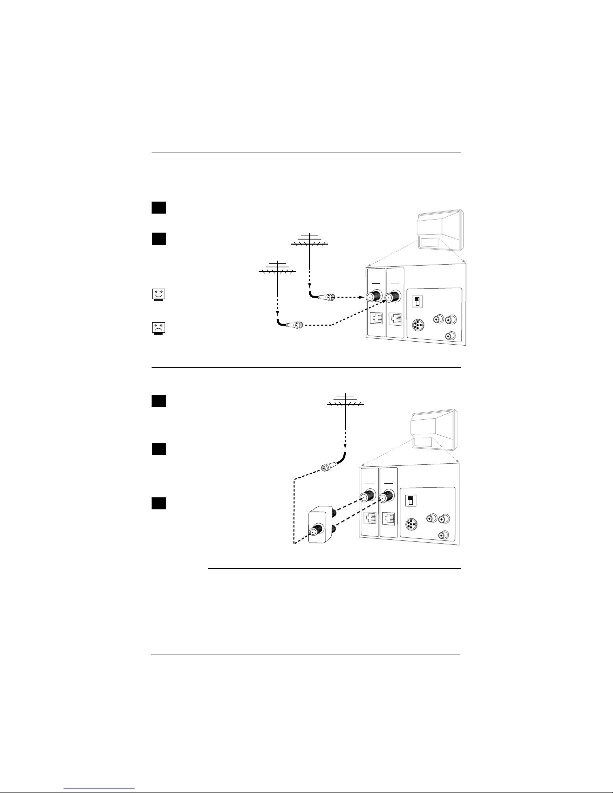
Off Air Antenna . . . . . . . . . . . . . . . . . . . . . . 8
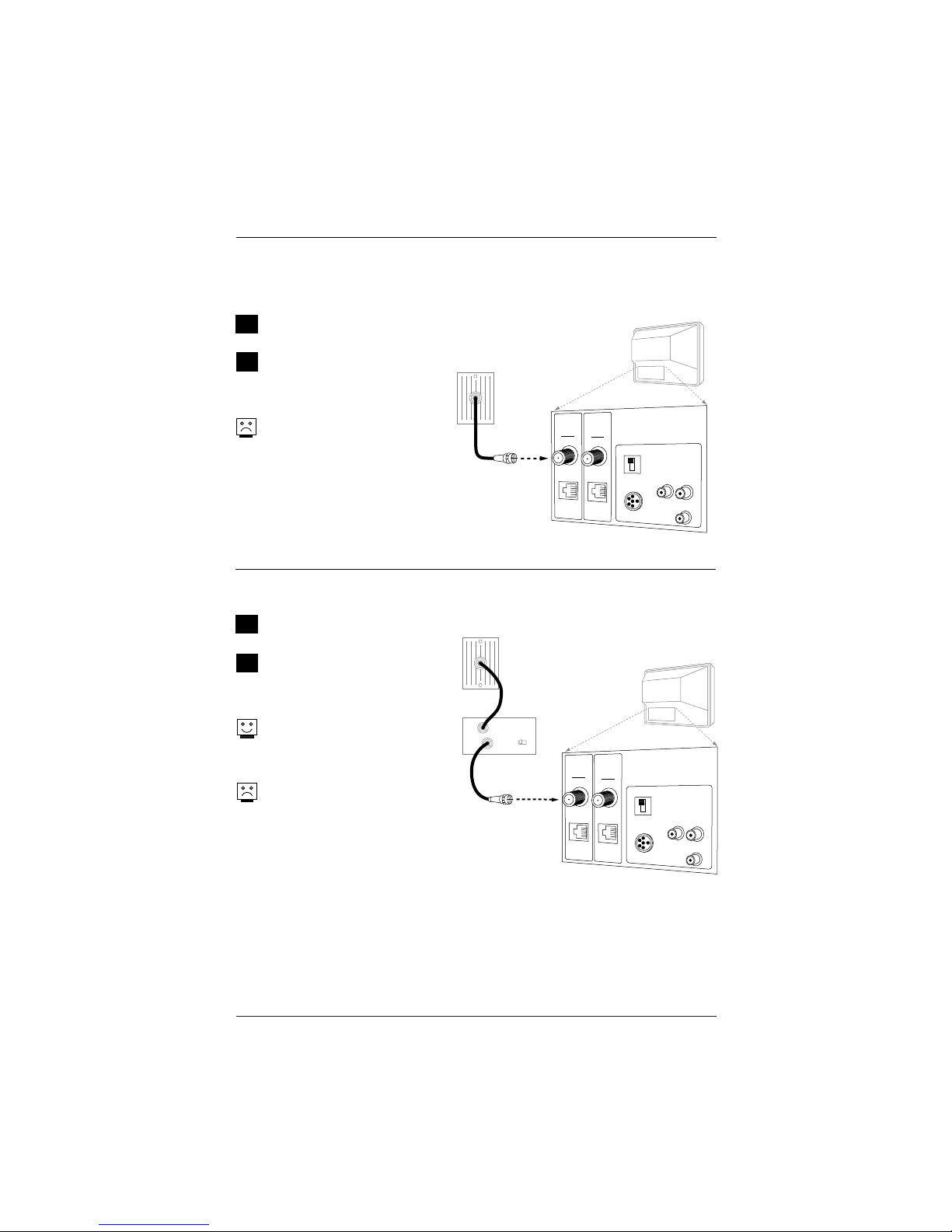
Cable Service . . . . . . . . . . . . . . . . . . . . . . . 9
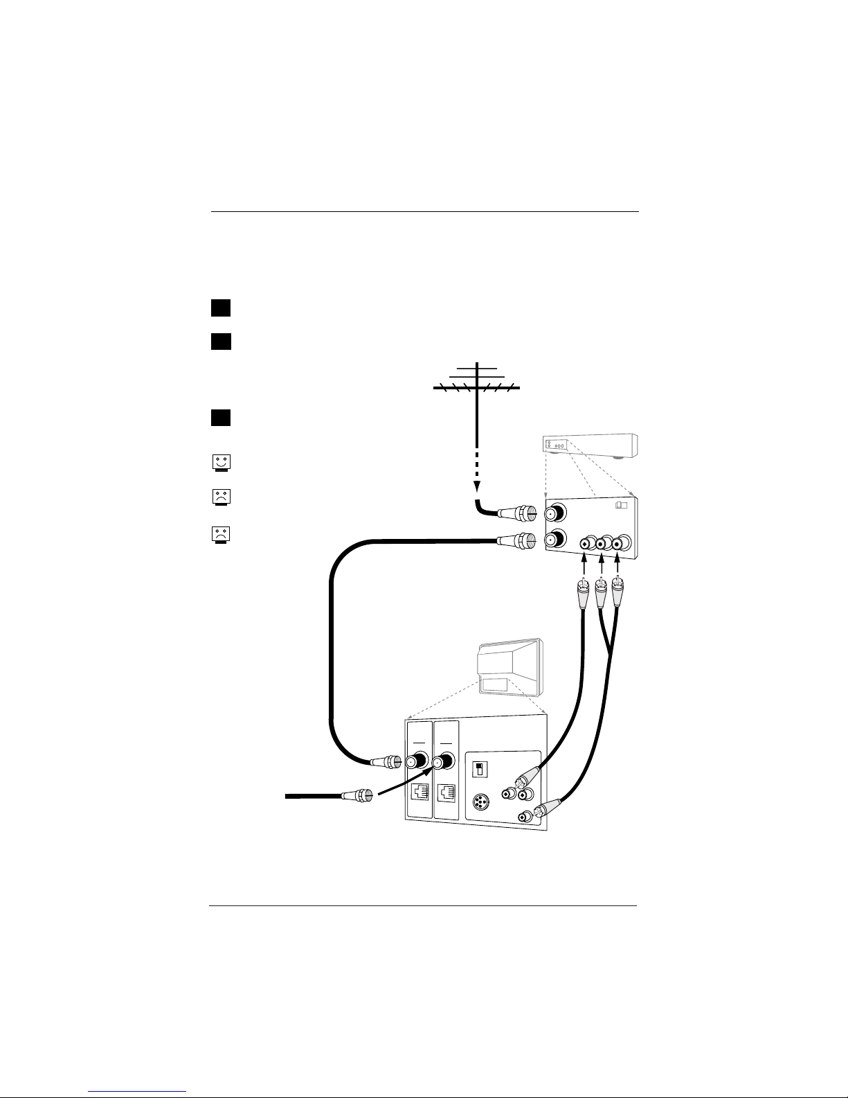
Off Air Antenna with VCR . . . . . . . . . . . . . . 10
Cable Service with VCR . . . . . . . . . . . . . . . . 11
Additional Equipment Hookup
Composite Video/Monaural Audio Hook Up . . . 12
External Speaker Hook Up . . . . . . . . . . . . . . 13
Pillow Speaker Connection & Setup . . . . . 14 - 15
Step 2. TV Reception Set Up & Channel Search
Installer/User Remote Control . . . . . . . . . . . . 16
Installing Batteries in Remote Control . . . . . . 17
Front Panel Controls . . . . . . . . . . . . . . . . . . 17
AC Power Cord . . . . . . . . . . . . . . . . . . . . . . 17
On-Screen Menus/Displays Overview . . . . . . . . 18
Other Menus and On-Screen Displays
Sleep Timer Menu . . . . . . . . . . . . . . . . . . . . 19
Channel/Time/Audio Display . . . . . . . . . . . . . 19
Digital CC Menu . . . . . . . . . . . . . . . . . . . . . 19
Volume Display . . . . . . . . . . . . . . . . . . . . . 19
Closed Captions Menu . . . . . . . . . . . . . . . . . 19
Captions Unknown display . . . . . . . . . . . . . . 19
Ch Preview Menu . . . . . . . . . . . . . . . . . . . . 19
Ghost Channel Display . . . . . . . . . . . . . . . . . 19
Step 3. Customize the TV’s Features
Setup Menu
Auto Program: Select Antenna, or Cable service
and start the channel search . . . . . . . . . . . . 20
Add/Del/Blank . . . . . . . . . . . . . . . . . . . . . 21
Channel Labels (Preset and Custom) . . . . 22 - 23
Custom Labels for Digital Channels . . . . . . . . 24
Clock Setup (Auto/Manual) . . . . . . . . . . . . . 25
Timer Setup (On/Off Timers) . . . . . . . . . . . . 26
Captions: Analog-Digital (Setup Overview) . . . 27
Captions: Analog-Digital Menu Structures . . . . 28
Audio Language . . . . . . . . . . . . . . . . . . . . . 29
Language . . . . . . . . . . . . . . . . . . . . . . . . . 30
Alarm Menu . . . . . . . . . . . . . . . . . . . . . . . 31
Video Menu . . . . . . . . . . . . . . . . . . . . . . . . 32
SAP: Digital Audio Program Selection . . . . . . . 33
Parental Control Menu . . . . . . . . . . . . . 34 - 37
Channel Banks Setup . . . . . . . . . . . 38 - 39 - 40
Installer Menus . . . . . . . . . . . . . . . . . 41 - 50
Using the Quickset II Clone Programmer . . 51 - 54
Clone Programmer Troubleshooting . . . . . . . . 54
Troubleshooting . . . . . . . . . . . . . . . . . 55 - 57
Maintenance . . . . . . . . . . . . . . . . . . . . . . . 57
Glossary . . . . . . . . . . . . . . . . . . . . . . . . . . 58
Notes . . . . . . . . . . . . . . . . . . . . . . . . . . . 59
Warranty . . . . . . . . . . . . . . . . . . . . Back Cover
Use this page as a reference for finding the pages or sections to go to
and set up the TV’s features for the end user
See the Master TV Setup on page 7
This TV functions differently than previous Zenith hospital sets. A Master TV setup must be created and
then transferred to the internal TV controller with 2-5-5+Menu. This action will transfer all digital informa-
tion and add important analog information to the TV controller.
Table of Contents

206-4065
TV Features Overview
A brief overview of the features on this TV
Analog and Digital Tuners
This TV is equipped with both analog and digital tuners. The analog tuner is used
for standard over-the-air antenna and cable type (CATV) sources. The digital tuner
is capable of receiving over-the-air digital programming.
After running Auto Program on the TV, analog channels will appear numerically
with Channel Up/Down and Digital Channels will appear numerically in the channel
scan after either the highest/lowest analog channel or Aux source.
Installer Menu Default Items
Some items explained in this guide may have different default settings than those
shown on the installer menu pages. As a result, those items may need to be reset
based on the requirements of the institution.
Note: Do not delete Aux Channel. If only digital channels are available, the only
user access to Parental Control will be the Aux channel.
Install a Two-way Signal Splitter?
If there is only one RF lead available, install a two-way splitter in order to be able
to provide 75 ohm RF leads to both the Antenna/Cable and Digital/Antenna inputs
on the TV connections panel.
Available Source Connections/Controls
• Antenna/Cable
• Digital/Antenna
• Composite Video with Monaural Audio
• External Speaker Output
• Pillow Speaker Control
• Front Panel Controls / Optional Remote Control Available
Features
Analog Menus Digital Menus
• Alarm Menu • Digital Captions (Note: Even though an OSD
• Captions/Text • Digital Video indicates that digital features
• Language • Digital Language are available, they may not be
• Parental Control • Digital Channels present on the actual channel
• Sleep Timer OSD picture and sound signals.)
• On/Off Timers
• Video Menu
• XDS Display
Page 6

Page 7
206-4065
H20J54DT Master TV Setup
This TV requires a different setup than previous Zenith hospital sets. A Master TV
setup must be created and then transferred to the internal TV controller with
2-5-5+Menu. The 2-5-5+Menu action adds to the TV controller important analog
setup information and all digital information. (Please refer to the sections men-
tioned below for more detailed instructions.) Note: The TV is capable of storing in
memory up to 140 digital broadcast and 125 analog channels.
Overview: Master TV Setup Procedure
Following are the steps necessary for setting up a Master TV. Once the Master TV is set up, it can be
copied into the clone programmer so that the TV customized features can be transferred to other
H20J54DT TVs. Note: After the Master TV setup has been successfully copied into the clone programmer,
the TV can be connected to auxiliary equipment like a DVD Player, VCR and Pillow Speaker.
1. Connect antenna or cable service to both RF inputs on TV. Plug TV into a standard AC power outlet.
Turn TV on and enter the Installer Menu.
a. If this is not a new TV, set Installer menu item 117-I RESET2DEFAULT, to 1and press ENTER.
When the menu returns to 0, the TV is ready to be set up. Exit Installer menu.
b. Re-enter Installer menu and set Item 3-I BAND/AFC.
- Broadcast signal, set to 0 - CATV signal, set to 1
c. Set item 28-I CH OVERIDE to 1 (Default).
d. Enable/disable all other installer menu items including Aux sources per your TV programming net-
work requirements.
e. After all your particular required installer menu item settings have been set, press ENTER on the
installer remote to remove and exit the Installer Menu.
2. Set up all TV menus/options and the features you want in the H20J54DT
(Video, Audio, V-Chip menus etc. See TV Clonable options page 52.)
3. Run Auto Program (Search for all available channels*.
All channels found analog and over-the-air digital will be entered into the TV’s four channel banks.)
a. Add Channel Labels to Channel OSDs.
• Add custom and preset channel labels. Add familiar network names like ABC, CBS, NBC etc.
b. Edit Channel Scan. In the Setup Menu, access the Channel Add/Del/Blnk menu.
• Review audio/video of “Found” channels. Determine channels to keep in your system.
• Delete channels per your system requirements. (Maximum is 140 off-air digital + 125 analog.)
• Review digital channel features. Add digital captions options.
(Digital channels are available after Auto Program has completed the channel search.)
4. Verify Master TV Setup
At this point, edit the Channel Banks and verify that the channel lineup, channel names and custom
labels etc. are correct.
• Make sure that all TV features, both analog and digital, are set per your system requirements.
5. Enter Installer menu, then press 2-5-5 and MENU on the remote. This action adds information to the
analog setup stored in the TV controller and Digital information; digital channels, digital features etc.
(If 2-5-5 + Menu is not done, all digital and some important analog information will not be added to
the master TV setup.)
• Enter Installer menu and set item 28-I CH OVER RIDE to 0. This action locks the channel scan.
Exit Installer menu.
After the preceding has been completed, the Master TV setup is ready to be copied to the LT2002 Clone
Programmer, see Clone Programmer section.
* Auto Program finds channels that have a signal present and are actively being broadcast. Some broad-
casters do not provide or broadcast a signal continuously. As a result, some DTV channels may not be
found in the channel scan. If you know there is a DTV channel that was not found by Auto Program, run
Auto Program again; when the DTV channel is actually sending out a program signal.

Page 8 206-4065
M.P.I.
Antenna
Cable
Typical
TV Back
M.P.I.
Digital
Antenna
RF Coaxial Wire
(75ohm)
Antenna
RF Coaxial Wire
(75ohm)
Antenna
PILLOW SPEAKER
TV SPEAKER
VIDEO IN SPEAKER OUT
AUDIO IN
M.P.I.
Antenna
Cable
Typical
TV Back
M.P.I.
Digital
Antenna
RF Coaxial Wire
(75ohm)
Antenna
75 ohm
Signal Splitter
PILLOW SPEAKER
TV SPEAKER
VIDEO IN SPEAKER OUT
AUDIO IN
Hook Up an Off Air Antenna
1
2
Locate the Antenna/Cable
and Digital/Antenna jacks on
the back of the TV.
Connect the RF antenna
wires that run from the wall
directly to the jacks, accord-
ing to the connection dia-
gram shown to the right.
If you have a 75 ohm RF
cable, then you don’t need
any adapters!
A 300 to 75 ohm adapter is
not included with the Zenith
TV.
Over-the-Air Antenna
To get digital with only one RF antenna lead, install a 2- way signal splitter
Mini Glossary
2-Way Splitter A device that provides two antenna signals from one antenna lead.
75 ohm The wire that comes from an off-air antenna or cable service provider. Each end
RF Cable looks like a hex shaped nut with a wire sticking through the middle, and it screws
onto the threaded jack on the back of the TV.
300 to (Not shown) A small device that connects a flat two-wire 300 ohm antenna to a 75
75 ohm ohm RF jack. They are usually about an inch long with two screws on one end and a
Adapter round opening with a wire sticking out on the other end.
1
2
If there is only one antenna lead
available from the wall antenna
jack, locate the Antenna/Cable
and the Digital/Antenna jacks on
the back of the TV.
Connect the antenna that runs
from the wall directly to a 75
ohm 2-way signal splitter (not
provided) according to the con-
nection diagram shown to the
right.
Connect the two antenna leads
to the TV RF inputs:
Antenna/Cable and Digital
/Antenna. This will provide the
same over-the-air signal to both
the analog and digital RF inputs.
3
Connect an over the air signal source to the TV

Page 9
206-4065
Cable TV
Wall Jack
M.P.I.
Antenna
Cable
Typical
TV Back
M.P.I.
Digital
Antenna
PILLOW SPEAKER
TV SPEAKER
VIDEO IN SPEAKER OUT
AUDIO IN
RF Coaxial Wire
(75ohm)
M.P.I.
Antenna
Cable
Typical
TV Back
M.P.I.
Digital
Antenna
Cable TV
Wall Jack
Cable Box
In
Out
RF Coaxial Wire
(75ohm)
3 4
output
switch
PILLOW SPEAKER
TV SPEAKER
VIDEO IN SPEAKER OUT
AUDIO IN
Hook Up Cable Service (CATV)
1
2
Locate the RF jacks on the back
of the TV set.
Connect the CATV cable that runs
from the wall to the
Antenna/Cable RF jack as shown
to the right.
The TV digital tuner does not
work with a Digital Cable signal
source.
Cable Service
Cable Service with a Cable Box
1
2
Locate the Antenna/Cable in jack
on the back of the TV set.
Connect the CATV cable that runs
from the wall to the cable box
and TV according to the connec-
tion diagram shown to the right.
If you’re using a cable box, tune
the TV to channel 3 or 4 and use
your cable box to change
channels.
If you’re using a cable box, Auto
Program might only find the
channel your cable service is on
(usually channel 3 or 4).
Connect cable service to the TV

Page 10 206-4065
PILLOW SPEAKER
TV SPEAKER
VIDEO IN SPEAKER OUT
AUDIO IN
M.P.I.
Antenna
Cable
Typical
TV Back
M.P.I.
Digital
Antenna
In
Out Audio
Video
3 4
VCR Back
VCR Back AV Panel
output
switch
A/V cables
not included
with TV
RF Coaxial Wire
(75ohm)
Antenna
Off Air
Antenna
RF Coaxial Wire
(75ohm)
Hook Up an Off Air Antenna with VCR
1
2
Locate the Antenna/Cable In jack on the
back of the VCR.
Connect the antenna that runs from the wall
jack directly to this jack, according to the
connection diagram shown to the right.
Connect a 75 ohm wire to the Digital
Antenna input on the TV for digital pro-
gramming.
Make the VCR to TV connections as indicated
in the illustration.
If you have a 75 ohm RF cable, then you
don’t need any adapters!
A 300 to 75 ohm adapter is not included
with the Zenith TV.
Over-the-Air Antenna with VCR
Connect an over-the-air signal source to the VCR and TV
3
No A/V cables are
included with the TV.

Page 11
206-4065
PILLOW SPEAKER
TV SPEAKER
VIDEO IN SPEAKER OUT
AUDIO IN
M.P.I.
Antenna
Cable
Typical
TV Back
M.P.I.
Digital
Antenna
In
Out Audio
Video
3 4
VCR Back
VCR Back AV Panel
output
switch
A/V cables
not included
with TV
RF Coaxial Wire
(75ohm)
Off Air
Antenna
RF Coaxial Wire
(75ohm)
Cable TV
Wall Jack
Cable Box
In
Out 3 4
Output
Switch
Hook Up a Cable Box with VCR
1
2
Locate the In jacks on the cable box and the
VCR.
Connect a 75 ohm cable between the cable box
wall jack and Cable In on the cable box.
Connect a 75 ohm cable from the Cable out jack
on the cable box to the Ant In jack on the VCR.
Connect a 75 ohm cable between the VCR out
jack on the VCR and the Antenna/Cable In jack
on the TV.
Connect a 75 ohm wire to the Digital Antenna
input on the TV to get digital programming.
Make the other VCR-TV connections as indicated
in the illustration.
For cable service without a cable box, connect a
75 ohm cable between the cable wall jack and
the VCR In jack.
Cable Service with VCR
Connect a cable box and VCR to the TV
3
4
5
6
No A/V cables are
included with the TV.

Page 12 206-4065
M.P.I.
Antenna
Cable
Typical
TV Back
M.P.I.
Digital
Antenna
Audio/Video
Cables
not included
with TV
Composite
Audio/Video
Device
Audio Out
Video Out
Right
Left
PILLOW SPEAKER
TV SPEAKER
VIDEO IN SPEAKER OUT
AUDIO IN
Hook Up Audio/Composite Video
1
2
Locate the audio/composite video input jacks on the TV.
Connect the audio/composite video input jacks to an audio/composite
video device as shown in the illustration.
Audio/Composite Video
Connect the TV to an audio/composite video source

Page 13
206-4065
Audio cable
not included
with TV
Audio In
Speaker Back
M.P.I.
Antenna
Cable
Typical
TV Back
M.P.I.
Digital
Antenna
PILLOW SPEAKER
TV SPEAKER
VIDEO IN SPEAKER OUT
AUDIO IN
Hook Up an External Speaker
Connect the TV to an external speaker or amplifier
1
2
External Speaker
Locate the Matrix Out jack on the back of the TV.
Connect the Matrix Out jack to an external speaker or
audio amplifier as indicated in the illustration.

Page 14 206-4065
TV
TV Back
TV Back Panel
(Expanded View)
PILLOW SPEAKER
TV
SPKR
PILLOW
SPKR Video
In Speaker
Out
Audio
In
M.P.I.
Antenna
Cable
M.P.I.
Digital
Antenna
Pillow Speaker Connection & Setup
1
2
Locate the Pillow Speaker output jack on the back of
the HealthView TV.
Connect an accessory pillow speaker or wired remote
control unit to this 6-pin jack.
Connect the pillow speaker as shown in the illustration.
Set the Pillow Speaker switch to Pillow Speaker setting.
Note: Once the switch is set to Pillow Speaker, no audio
will be heard from the TV speakers.
Pillow Speaker Setup
Pillow speaker is not included with the HealthView TV
3
Use a pillow speaker by Curbell, Model A-16455-02 or
other UL recognized pendant control bearing the warn-
ing: “Risk of fire if used in oxygen enriched atmos-
phere. Keep pendant control away from oxygen
equipment.”
4
Controlling the TV with Serial Data
The TV is capable of being controlled by a single-
wire, serial data signal. This is a Zenith patented
technology and is being implemented by certain
brands of “smart” pillow speakers, such as Curbell’s
“GEN-II” models.

Page 15
206-4065
Pillow Speaker Setup
Connect a pillow speaker to the TV
Pillow Speaker Control
Pillow Speaker Interface
This connector furnishes three control lines and an audio output. A patient-pendant remote control, or
entertainment audio and nurse call system may be connected here. All lines are isolated from the AC
power line and earth ground. (Opto-isolators isolate the control lines, and a transformer isolates the
audio. There are no relays or inductive components in the control lines.)
3
TV
ON/OFF CHAN
DOWN CHAN
UP
(MALE
PLUG)
VOLUME CONTROL
SPKR. 5
1
4
6
2
1
2
3
4
5
6
3
1
5
2
4
6
TV ON/OFF
OPEN
CHAN UP/DATA IN
COMMON
AUDIO OUT
CHAN DOWN
Controlling the TV with Mechanical Switches
Pin 4 (common) is momentarily connected to pin
1, 3, or 6 via push-action switches to control
On/Off and Channel Up/Down. These pins are at
+13 volts DC (when measured from pin 4) with
the switches open. Current draw is 8 mA when a
switch is closed. (This operation is identical to
previous Zenith models using the 5-Wire Interface
except that only +7 volts DC was supplied and
current draw was only 2.5 mA.)
Pin No. Purpose
1 External TV On/Off switch.
2 (Not used.)
3 External Channel Up switch or Data in.
4 Common connection for control, data, and audio
output. Impedance to earth ground is a 10-meg
resistor in parallel with a 1100 pf capacitor.
5 Isolated audio output. Nominal 14-ohm source
impedance with short circuit protection. Intended for
a pillow speaker with a low-impedance pad-type volume
control.
6 External Channel Down switch.

Page 16 206-4065
MUTE
Turns sound Off and On,
while the picture remains.
CHANNEL PREVIEW*
Allows Parental Control
access on analog channels:
set V-Chip blocks for ana-
log/digital programming.
BANK
Selects channel banks
1-2-3-4.
SAP
Chooses other digital audio
languages if available from
broadcaster.
OK (Enter)
Press to view the
Channel/Time display or to
remove any on-screen dis-
play or menu.
Number Keypad
Select channels directly;
key in channel numbers
and press OK (Enter).
-DASH (-)
For entering digital chan-
nel numbers e.g. 7-1, 11-3
etc.
(SLEEP) TIMER
Press repeatedly to choose
a TV turn-off time up to 4-
hours.
MENU / ADJ (Adjust
Up/Down/Left/Right)
Selects and adjusts on-
screen menu options.
Press MENU repeatedly to
scroll through menus. Use
ADJ (Adjust) Up / Down /
Left / Right to choose and
change selected option.
Optional Installer/User Remote Control
3140OSKZ003AR6
MUTE POWER
BANK GUIDE
CH
PREVIEW
SAP INFO CC
OK
VOL
CH
CH
VOL
FLASHBK
TIMER ALARM
MENU
ADJ
ADJ ADJ ADJ
BED1 BED2
Keys descriptions and functions for the optional remote
Remote Control
Part Number 3140OSKZ003AR6
(Remote not included with TV)
Audio Languages: Availability of audio languages are determined only by each broadcaster and
may not be available on all digital programs.
POWER
Turns TV On or Off.
GUIDE
Not functional.
INFO
Not functional.
CC (Closed Captions)
Press to turn closed cap-
tions On/Off. Press ENTER
to exit menu. In digital
captions, selects next cap-
tion language.
VOLUME Down/Up
Adjusts the sound level.
CHANNEL (Up/Down)
Scrolls available channels,
(analog to digital) and the
Aux Channel (Audio/Video
source).
FLASHBK (FLASHBACK)
Returns to the previously
tuned channel.
ALARM
Press to display menu.
Follow on-screen instruc-
tions to set a time for the
TV to turn itself on.
BED1 / BED2
Switch selects remote
operating mode.
*Note: Ch Preview cannot
be accessed while tuned
to a digital channel. Set
V-Chip blocks while tuned
to an analog channel.

Remove the back of
the remote control
and install two
high-quality AA
batteries.
Match “+” with “+”
and “-” with “-”.
(Remote not included with TV)
Page 17
206-4065
Front Panel Controls
A
B
Using the front panel controls to operate the TV
C
Power
Turns TV on and off.
Channel (Down/Up)
Chooses next available channel.
Volume (Down/Up)
Decreases/increases sound level.
CC (Captions/Text)
Turns selected caption/text option On and Off. (Depending on TV captions setup.)
power
channel
volume
captions
D
A
B
C
D
Install Batteries into Remote Control
AA +
AA +
After all con-
nections have
been made,
plug the TV and
all system
equipment into power sources as
applicable. This TV is designed to
operate on standard current 120-volt
60 Hertz AC power.
Plug TV into AC Power Outlet

Page 18 206-4065
On-Screen Menus/Displays Overview
Descriptions of the menus and on-screen status displays
Using MENU and the other keys indicated on the optional Installer’s remote,
the installer can access the menus/displays described below.
On-Screen Menus
Setup Menu Adjusts the basic characteristics of the TV.
Auto Program 20 Automatically finds and stores active channels to scroll
through using Channel Up/Down.
Add/Del/Blnk 21 Manually pick and choose which active channels will
appear when using Channel Up/Down.
Channel Labels 22 Label the channels with their network names (ABC, CBS,
HBO, etc.).
Clock Set 25 Sets the time on the TV.
Timer 26 Sets the TV’s automatic turn On/Off times.
Captions 27 Analog-Digital Captions (Caption/Text) Setup Overview.
Captions Menus 28 Analog-Digital Captions Menus Structures.
Audio Language 29 Sets the digital audio language, if available on program.
Language 30 Chooses the language the on-screen menus will appear in.
Alarm Menu 31 Set a time for the TV to turn itself on.
Video Menu 32 Customizes the picture. The options are: Contrast,
Brightness, Color, Tint, Sharpness, Picture Pref, and Aspect
Ratio (Aspect Ratio is only for Digital Channels).
Audio Language 33 Selects available Digital audio languages.
Menu
Parental 34 Allows user to block program content or the A/V sources
Control Menu for up to 99 hours, with the use of a password.
Other Menus and On-Screen Displays
Volume 19 Shows current sound level setting; press VOLUME Up/Down
to activate.
Channel/Time 19 Shows the current time, channel, video or mute, and XDS
info; press OK to activate.
Ch Preview 19 Displays the available channels list; press CH PREVIEW.
(Only Analog Channels are displayed not Digital).
Captions/Text 19 Turns selected Caption/Text option On and Off; press CC to
activate.
Sleep Timer 19 Sets the time the TV will turn Off.
Ghost Channel 19 Shows the current channel number in red scrolling down
the screen. Refer to Installer menu to turn Off.
Alarm 19 Sets a time for the TV to automatically turn itself On.

Page 19
206-4065
5 - - - -
9 - - - -
20 - - - -
32 - - - -
2 - - - -
AUX - - - -
21
VOLUME
Ch 25 - PBS
7:15 PM
MONO
XDS Information As Available
CHANNEL PREVIEW
CH TO SELECT, ENTER TO QUIT
CC FOR PARENTAL CONTROL
SLEEP TIMER
OFF
PRESS TIMER
CC CAPTION 1 IS ON
ALARM MENU
TIME NOW 3:11 PM
6:10 AM TIMER
PRESS DIGITS TO SET TIME
TIMER TO SELECT AM/PM
CC CAPTIONS UNKNOWN CC CAPTIONS ENGLISH
LENGTH 00:32 TIME LEFT 00:42
Other Menus and On-Screen Displays
Press the remote keys indicated below to access these menus and displays
Volume Display
Press VOLUME. Shows current
sound level.
Closed Captions Menu
Press CC. Turns selected option
on or off for both analog and
digital captions. See Caption /
Text pages to set up options.
Captions Unknown Display
Press CC, if captions are not
known, this display appears.
Channel/Time/Audio Display
Press ENTER. Shows selected
channel or source, time if the
clock is set, incoming audio
signal, and XDS* info if avail-
able on program. For XDS wait
5 seconds and press ENTER.
Sleep Timer Menu
Press TIMER. Shows remaining
time before TV turns itself off.
Select a preset turn-off time
from 10 minutes up to 4
hours.
Alarm Menu
Press Alarm. Sets a time for
the TV to automatically turn
itself On.
Ch Preview Menu
Press CH PREVIEW*. Shows list
of TV Analog Channels, AUX
source, and provides access to
the Parental Control menu.
Ghost Channel Display
Channel number appears in red
on the right side of the screen
and slowly scrolls downward.
To disable the Ghost Channel,
see Installers menu.
Digital Captions Menu
Press CC to scroll each digital
captions language, if available
and to turn captions on/off.
News and local programming 5:50 PM
Thu Jan 19, 2007 4:00 PM 6:00 PM DTV 66-1
Dolby Digital HD
Multi-lingual 16:9 1080i TV-PG
Digital Channels On-Screen Display
Press ENTER twice to see the on-screen display for digital channels. Reveals channel number and program
details: Title, day, time, languages available, video formats available, closed captions options, etc.
*Not available on digital channels.

Page 20 206-4065
Auto Program (Channel Search)
Using the optional Installer’s
remote control, press POWER to
turn the TV on.
Press MENU repeatedly until the
Setup menu appears.
Use Up or Down ADJ on the
remote control to highlight Auto
Program on the menu.
Press the Right or Left ADJ arrow
to begin the Channel Search.
Press OK when the channel search
is complete. This is when the two
progress bars are filled and the
message “COMPLETED SUCCESSFUL-
LY” appears on the screen.
Auto Program finds channels being received
by the TV’s analog and digital tuners.
Cable will not work unless you subscribe to a
cable service.
After the channel search is complete, use
the features on the following pages to:
Add/Delete/Blank channels. Include channel
labels, so that they will appear on the chan-
nel / time display. Choose from the preset
label selections for analog and create your
own labels for digital channels.
Note: Use item 3-I Band/AFC in Installer menu to select proper analog tuning band (0=CATV, 1=Broadcast
etc.) before running Auto Program.
1
2
3140OSKZ003AR6
MUTE POWER
BANK GUIDE
CH
PREVIEW
SAP INFO CC
OK
VOL
CH
CH
VOL
FLASHBK
TIMER ALARM
MENU
ADJ
ADJ ADJ ADJ
BED1 BED2
AUTO PROGRAM
ADD/DEL/BLNK
CH. LABELS
CLOCK SET
TIMER
CAPTIONS
AUDIO LANG.
LANGUAGE
TO PROGRAM
SETUP MENU
2
3
4
3
4
55
1
Table of contents
Other LG TV manuals