LG WM1815CS User manual

100
WASHING MACHINE
SERVICE MANUAL
READ THIS MANUAL CAREFULLY TO DIAGNOSE
PROBLEMS CORRECTLY BEFORE SERVICING THE UNIT.
MODEL: WM1812CW/WM1814CW/WM1815CS
CAUTION
Website: http: //www.LGEservice.com
E-mail: http: //www.LGEservice.com/techsup.html
!

101
JUN. 2004 PRINTED IN KOREA
P/No.: 828ER 027F

2
CONTENTS
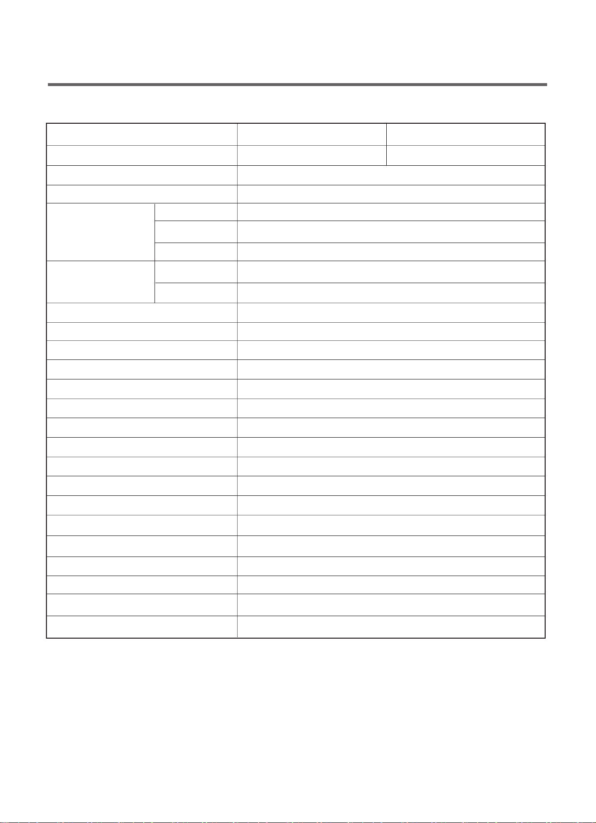
1. SPECIFICATIONS .........................................................................................................................
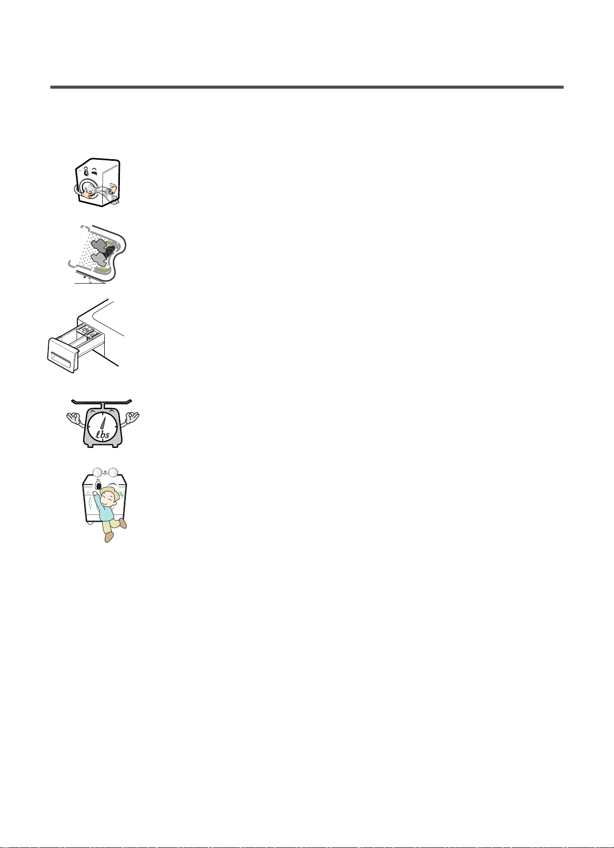
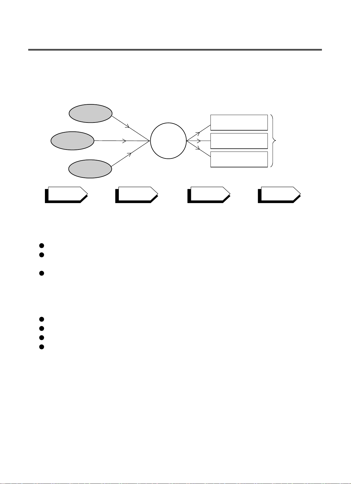
2. FEATURES & TECHNICAL EXPLANATION ................................................................................ 4
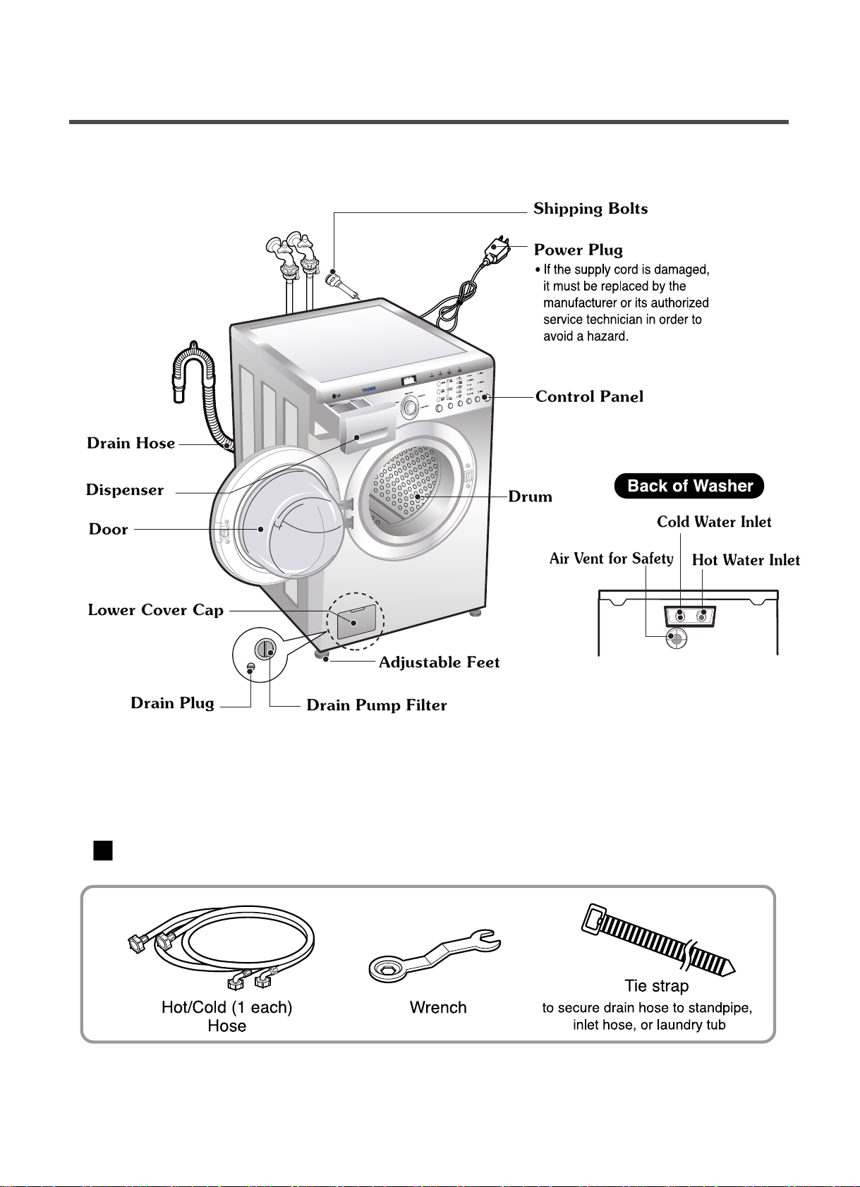
. PARTS IDENTIFICATION ............................................................................................................ 7
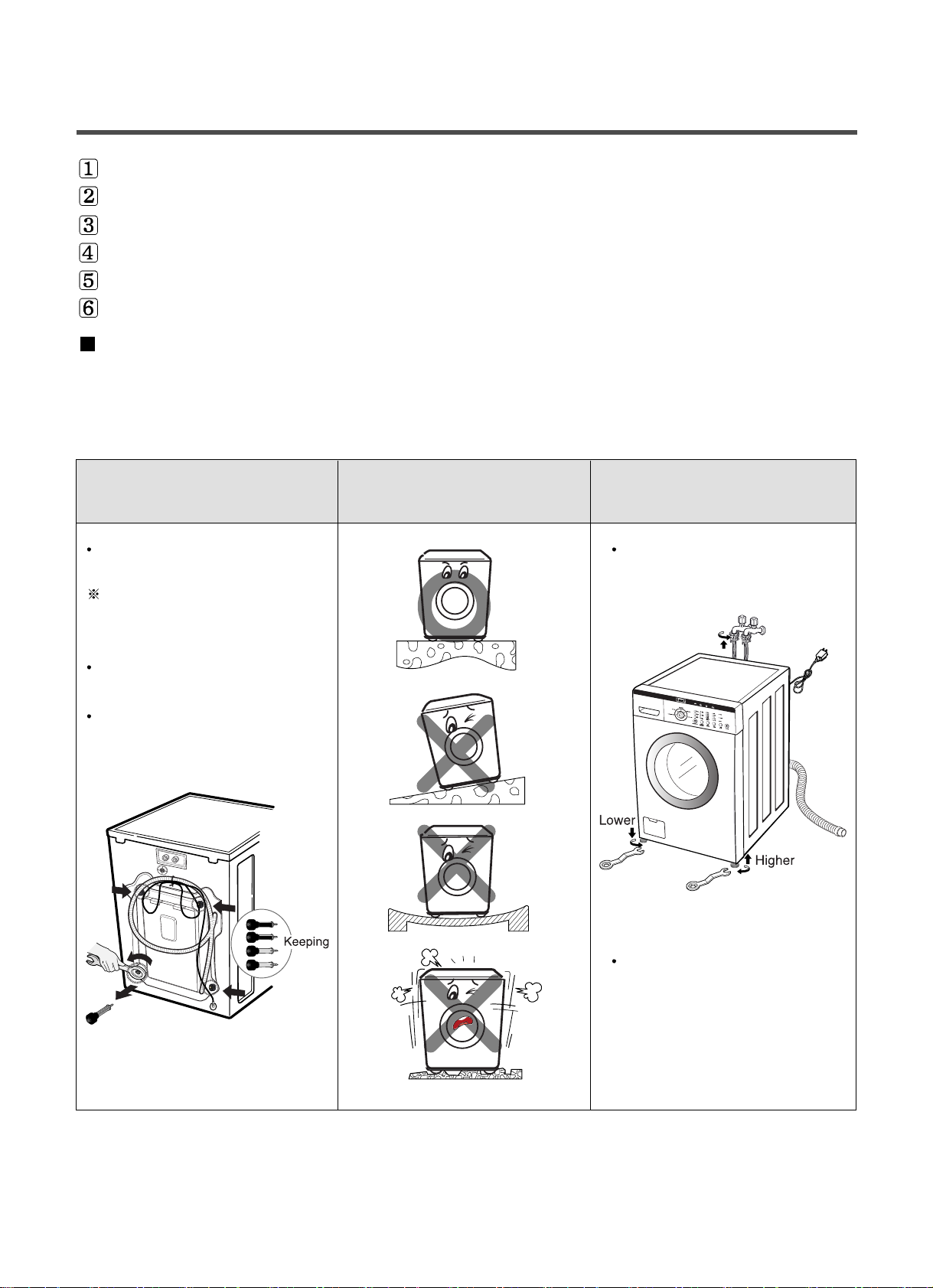
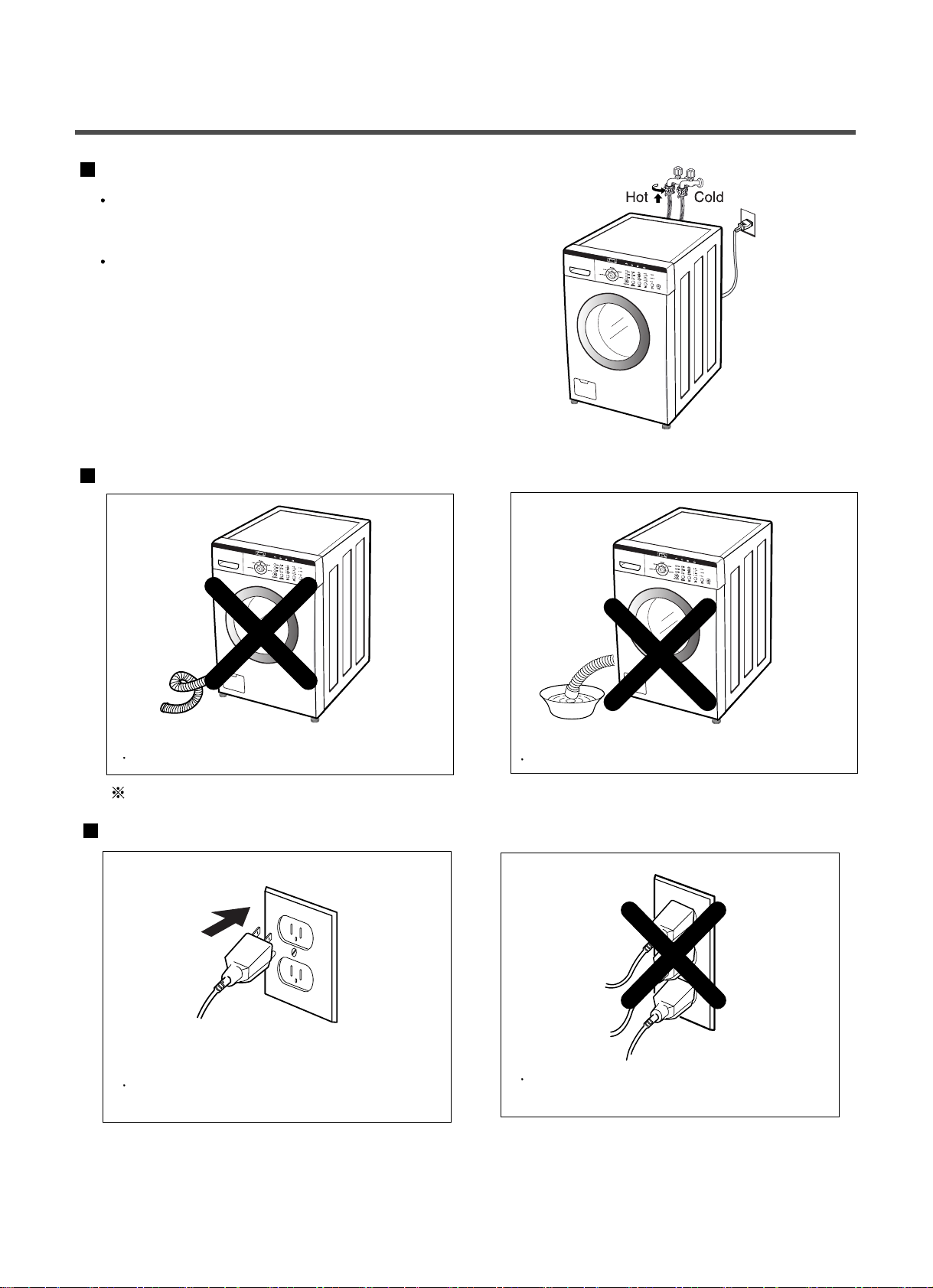
4. INSTALLATION & TEST ............................................................................................................... 8
5. OPERATION ................................................................................................................................11
6. WIRING DIAGRAM/PROGRAM CHART.....................................................................................14
7. TROUBLESHOOTING.................................................................................................................16
7-1. BEFORE PERFORMING SERVICE ...................................................................................16
7-2. QC TEST MODE.................................................................................................................16
7- . HOW TO CHECK THE WATER LEVEL FREQUENCY ......................................................16
7-4. ERROR DISPLAY ...............................................................................................................17
8. ERROR DIAGNOSIS AND CHECK LIST ....................................................................................19
8-1. DIAGNOSIS AND SOLUTION FOR ABNORMAL OPERATION ........................................19
8-2. FAULT DIAGNOSIS AND TROUBLESHOOTING ..............................................................22
9. DISASSEMBLY INSTRUCTIONS ............................................................................................... 1
10. EXPLODED VIEW .....................................................................................................................40
10-1. CABINET & CONTROL PANEL ASSEMBLY....................................................................40
10-2. DRUM & TUB ASSEMBLY................................................................................................41
10- . DISPENSER ASSEMBLY .................................................................................................42
4
7
8
11
12
1
1
1
1
14
16
16
19
26
4
4
5
6

3
1. SPECIFICATIONS
ITEM WM1812CW/WM1814CW WM1815CS
COLOR BLUE WHITE TITANIUM
POWER SUPPLY AC 120 V, 60 Hz
PRODUCT WEIGHT 173 lbs. (78.5 kg)
WASHING 280 W
DRAIN MOTOR
80 W
WASH HEATER –
WASH 46 rpm
SPIN 0-900 rpm
CYCLES 5
WASH/RINSE TEMPERATURES 5
SPIN SPEEDS 5
OPTIONS
Prewash, Quick Cycle, Extra Rinse, Rinse+Spin, Delay Wash
CUSTOM PROGRAM –
WATER CIRCULATION –
OPERATIONAL WATER PRESSURE 4.5
-
116 psi (800 kPa)
CONTROL TYPE Electronic
WASH CAPACITY 2.96 cu. ft (3.42 cu. ft. IEC)
DIMENSIONS 27” (W) X 30
1/
32” (D) X 38
11/
16” (H), 50
13/
16” (D, door open)
DELAY WASH up to 9 hours
DOOR SWITCH TYPE PTC + Solenoid
WATER LEVEL 9 steps (by sensor)
LAUNDRY LOAD SENSING Incorporated
ERROR DIAGNOSIS Incorporated
AUTO POWER OFF Incorporated
CHILD LOCK Incorporated
ELECTRIC POWER
CONSUMTION
REVOLUTION SPEED

4
2. FEATURES & TECHNICAL EXPLANATION
2-1. FEATURES
■Direct Drive System
The advanced Brushless DC motor directly drives the drum without
belt and pulley.
■Tilted Drum and Large Door Opening
Tilted drum and large opening make it possible to load
and unload clothing more easily.
■Time-Released Dispenser
Detergent, fabric softener and bleach are dispensed separately at
the right time during wash cycle.
■Automatic Wash Load Detection
Automatically detects the load and optimizes the washing time.
■Child Lock
The Child lock prevents children from pressing any button to
change the settings during operation.
추가선택, 예약,
5

5
2-2. NEURO FUZZY WASHING TIME OPTIMIZATION
To get the best washing performance, optimal time is determined by the water temperature,
the selected washing temperature, and the size of the load.
2- . WATER LEVEL CONTROL
This model incorporates a pressure sensor which can sense the water level in the tub.
The water supply is stopped when the water level reaches the preset level, the washing
program then proceeds.
Spinning does not proceed until the water in the tub drains to a certain level.
2-4. DOOR CONTROL
The door can be opened by pulling the door handle whenever washer is not in operation.
When the cycle is completed, the DOOR LOCKED light will turn off.
If a power failure has occurred while in operation, the door will unlock after 5 minutes.
Clicking sounds can be heard when the door is locked/unlocked.
NEURO-
FUZZY
load
size
selected
washing
temperature
water
temperature
washing time
rinsing time
spin rhythm, time
the best
washing
performance
SENSING
PROCESSING
DETERMINATION
EFFECT

6
2-5. THE DOOR CAN NOT BE OPENED
While program is operating
When a power failed and power plug is taken out in operation
While Door Lock lights turn on.
White the motor is in the process of intertial rotating, through the operation is paused.
2-6. DOOR LOCKED LAMP LIGHTS
When the frequency of water level is lower than 22.9 kHz
(It can be canceled when the frequency is more than 2 .8 kHz)
When the temperature inside the tub is higher than 45 °C and water level is not 25.5 kHz
(It can be canceled when the water level is 25.5 kHz or the temperature inside the tub is lower than 40 °C)
2-7. CHILD LOCK
Use this option to prevent unwanted use of the washer. Press and hold OPTION button for seconds to
lock/unlock control.
When Child lock is set, “ ” blinks and all buttons are disabled except the Power button. You can lock
the washer while it is operating.

7
. PARTS IDENTIFICATION
ACCESSORIES
울
란제리
란제리

8
Before servicing, ask the customer what the trouble is.
Check the setup (power supply is 120 V AC, remove the transit bolts....).
Check with the troubleshooting guide.
Plan your service method by referring to the disassembly instructions.
Service the unit.
After servicing, operate the appliance to see whether it functions correctly.
STANDARD INSTALLATION
The appliance should be installed as follows:
REMOVE THE SHIPPING INSTALL THE APPLIANCE ADJUST THE
BOLTS
ON A FLAT AND FIRM SURFACE
LEVELING
Remove the 4 shipping bolts Turn the leveling feet to adjust
with the supplied wrench. the appliance.
Do first lower side to remove easily.
Keep the shipping bolts and
spanner for future use.
Insert the 4 caps
(provided) into the hole.
Turn clockwise to raise;
counterclockwise to lower.
4. INSTALLATION & TEST

9
HOW TO CONNECT THE INLET HOSE
Verify that the rubber washer is inside of the
valve connector.
Tighten the inlet hose securely to prevent leaks.
CONNECT THE DRAIN HOSE
CONNECT POWER PLUG
The end of the drain hose should be placed less than 96
”
from the floor.
Connect the power plug to the wall outlet. Avoid connecting several electric devices, as
doing so may cause a fire.
Make sure that the hose is not twisted. Avoid submerging the end of the hose.

10
SOFTENER
MAX
TEST OPERATION
Connect the power plug to
the outlet.
Connect the inlet hoses.
Power off and the power on.
Press the SPIN SPEED button.
Press the START/PAUSE button.
Check the spin and drain
functions.
Listen for a click to determine
if the door is unlocking.
Listen for a click to determine if
the door has locked.
If SVC is needed during check,
remove the remaining water by
pulling out the hose cap.
Preparation for Press the POWER button. Press
the
Start/Pause
washing. button.
Press the WASH/RINSE button Check if the drum rotates Check if water is supplied
and the present temperature will
clockwise and counterclockwise.
through the detergent dispenser.
be displayed.
Check the water Check the automatic Check the water supply.
temperature. reverse rotation.
Check the drain and spin
Press the
Water removal
functions.
START/PAUSE button.

11
5. OPERATION
EST. TIME REMAINING
• This display shows:
a) the estimated time remaining
in the cycle when operation.
b) an error code when an error
has been detected.
CYCLE SELECTOR
• Press the Cycle selector to
select cycle designed for
different types of fabric and
soil levels.
START/PAUSE button
• Use this button to start/stop the
washer.
WASH,RINSE temp., SPIN SPEED, SOIL LEVEL button
• Select a water temperature based on the type of load you are washing.
• To change the spin speed, press the Spin Speed button repeatedly
to cycle through available options.
• To change the soil level, press the Soil evel button repeatedly until
the desired setting is on.
OPTION button
• Prewash : Use this option for
loads that need pretreatment.
It adds 16 minutes prewash and drain.
POWER button
• Use this button to turn
power On/Off.
• Quick Cycle : The Quick offers a quick
cycle time.
• Rinse+Spin : Use this option to rinse
and then spin.
BEEPER, DELAY WASH, EXTRA RINSE button
• Use the Beeper button to turn the Beeper On/Off.
• Delay Wash allows the start of any cycle to be delayed for 1~9
hours.
• Extra Rinse provides an additional rinse.
DOOR LOCKED lamp
• ight whenever the door of the washer is locked.
• The door can be unlocked by pressing the Start/Pause
button to stop the washer.

**
Cool-down **Approx.
(Minutes)
* Wash time is in minutes.
** The total working time will vary with the load size,
water temperature and ambient temperature.
12
6. WIRING DIAGRAM/PROGRAM CHART

13
7. TROUBLESHOOTING
7-1. BEFORE PERFORMING SERVICE
Be careful of electric shock when disconnecting parts while troubleshooting.
The voltage of each terminal is 120 V AC and DC when the unit is plugged in.
7-2. QC TEST MODE.
The washer must be empty and the controls must be in the off state.
1. Press the SPIN SPEED and SOIL LEVEL buttons simultaneously.
2. Press the Power button, while the above condition. Then buzzer will sound twice.
. Press the Start/Pause button repeatedly to cycle through the test modes.
7- . HOW TO CHECK THE WATER LEVEL FREQUENCY
Press the
SPIN SPEED and SOIL LEVEL button simultaneously.
So, for example a display indicating 241: a Water level frequency of 241 x.1 kHz
= 24.1 kHz
The digits indicate the water level frequency ( x.1 kHz ).
Check Point Display Status
None Turns on all lamps and locks the door.
1 time Tumble clockwise. rpm (40~50)
2 times Low speed Spin. rpm
times High speed Spin. rpm
4 times Inlet valve for prewash turns on. Water level frequency (25~65)
5 times Inlet valve for main wash turns on. Water level frequency (25~65)
6 times Inlet valve for hot water turns on. Water level frequency (25~65)
7 times Inlet valve for bleach turns on. Water level frequency (25~65)
8 times Tumble counterclockwise. rpm (40~50)
9 times
Water temperature (Thermistor) Water temperature [°C]
10 times
Drain pump turns on.
Water level frequency (25~65)
11 times
Power off and unlock the door.
Turn off all lamps.
Number of times the
Start/Pause button is pressed

14
7-4. ERROR DISPLAY
If you press the START/PAUSE button when an error is displayed, any error except will
disappear and the machine will go into the pause status.
In case of if the error is not resolved within 20 sec., or the in case of other errors,
if the error is not resolved within 4 min., power will be turned off automatically and the error code will
blink. But in the case of , power will not be turned off.
ERROR SYMPTOM CAUSE
WATER INLET
ERROR
• Correct water level (246) is not reached within 8 minutes
after water is supplied or it does not reach the preset water
level within 25 minutes.
• The load is too small.
• The appliance is tilted.
• Laundry is gathered to one side.
• Non distributable things are put into the drum.
1
2
IMBALANCE
ERROR
• Not fully drained within 10 minutes.
3
DRAIN
ERROR
• Water is overflowing (water level frequency is over 21 ).
※If is displayed, the drain pump will operate to
drain the water automatically.
4
OVER FLOW
ERROR
• The SENSOR SWITCH ASSEMBLY is out of order.
5
PRESSURE
SENSOR
ERROR
• Door not all the way closed.
• Loose electrical connections at Door switch and
PWB Assembly.
• The DOOR SWITCH ASSEMBLY is out of order.
6
DOOR OPEN
ERROR
• The THERMISTOR is out order.
7
THERMISTOR
ERROR

15
ERROR SYMPTOM CAUSE
OVER
CURRENT
ERROR
•
MAIN PWB
ASSEMBLY is out of order.
•
Winding in the STATOR ASSEMBLY is short-circuited.
• The connector ( -pin, male, white) in the MOTOR
HARNESS is not connected to the connector
( -pin, female, white) of STATOR ASSEMBLY.
• The electric contact between the connectors
( -pin, male, white) in the MOTOR HARNESS
and 4-pin, female, white connector in the MAIN PWB
ASSEMBLY is bad or unstable.
• The MOTOR HARNESS between the STATOR
ASSEMBLY and MAIN PWB ASSEMBLY is cut (open
circuited).
• The hall sensor is out of order/defective.
8
9
LOCKED
MOTOR
ERROR
• Loose Ball Sensor Connector.
• Ball Sensor is out of order.
※Displayed only when the START/PAUSE button is first
pressed in the QC Test Mode.
10
BALL SENSOR
ERROR
•
The washer experienced a power failure.
12
POWER
FAILURE
• EEPROM is out of order.
※Displayed only when the START/PAUSE button is first
pressed in the QC Test Mode.
11
EEPROM
ERROR

16
8-1. DIAGNOSIS AND SOLUTION FOR ABNORMAL OPERATION
8. ERROR DIAGNOSIS AND CHECK LIST
SYMPTOM GUIDE FOR SERVICE CALL
No power
Water inlet trouble
YES
YES
YES
NO
NO
YES
NO
NO
Is the power plug connected firmly to
120 V AC outlet?
Power failure? or Breaker opened?
Is the outlet controlled by a switch?
Visit to service.
Is displayed?
Is the tap opened?
Is the tap frozen?
Is the water supply shut-off?
Is filter in the inlet valve clogged with
foreign material?
Visit to service.
Clean the filter of
inlet valve

17
SYMPTOM GUIDE FOR SERVICE CALL
Door error
Drain trouble
Was the load too large?
Visit to service.
Visit to service.

18
SYMPTOM GUIDE FOR SERVICE CALL
Suds overflow from the
appliance.
(In this condition, wash and
spin do not operate normally)
YES
YES
YES
YES
SOFTENER
MAX
(4) Main Wash Compartment
4
Is a low-sudsing detergent used?
Is the proper amount of detergent used
as recommended?
Recommend to reduce the amount
of detergent.
Is liquid laundry product put in the correct
compartment of the dispenser?
Is the cap clogged?
Explain proper use of liquid laundry products.
Clean the compartment.
Visit to service.
LOW-SUDSING
This appliance has an automatic suds sensing function which
prevents overflow.
When excessive suds are sensed, the suds removing
implementations such as drain, water input, pause will operate,
without rotating the drum.
Liquid laundry products do not
flow in.

19
NO
YES
YES
YES
YES
NO
NO
NO
NO
YES
(1)
(2)
Is the supplied voltage 120 V AC?
Is the voltage between the pins of 2 FILTER
ASSEMBLY connector 120 V AC?
Is the LED (1) on?
Are the connectors (2) on the PWB loose?
Is wire of the DISPLAY PWB ASSEMBLY
broken?
Replace DISPLAY PWB ASSEMBLY
or repair wire.
Check the fuse or reset
the circuit breaker.
Replace the FILTER
ASSEMBLY (CIRC).
Replace MAIN PWB
ASSEMBLY.
Reconnect.
Replace the MAIN PWB
ASSEMBLY.
NO POWER
8-2. FAULT DIAGNOSIS AND TROUBLESHOOTING
1. Be careful of electric shock if disconnecting parts while troubleshooting.
2. First of all, check the connection of each electrical terminal with the wiring diagram.
. If you replace the MAIN PWB ASSEMBLY, reinsert the connectors correctly.
CAUTION
Other manuals for WM1815CS
2
This manual suits for next models
2
Table of contents
Other LG Washer manuals