LGL ECOMPACT2 User manual

ALIMENTATORE DI FILO A SPIRE SEPARATE
YARN ACCUMULATOR WITH SEPARATE COILS
DISPOSITIF D’ALIMENTATION DE FIL À BOBINES SÉPARÉES
SCHUSSFADENGEBER MIT GETRENNTEN WINDUNGEN
ALIMENTADOR DE HILO DE ESPIRAL SEPARADOS
İPLİK ARASI MESAFELİ İPLİK BESLEYİCİSİ
セパレート型コイル式 ヤーンアキュームレータ
MANUALE DI ISTRUZIONE
INSTRUCTION MANUAL
NOTICE D'INSTRUCTION
BEDIENUNGSANLEITUNG
MANUAL DE INSTRUCCION
KULLANMA KILAVUZU
取扱説明書

Scope of supply: Design, manufacture and after sales service of yarn feeders,
measuring winders, stands, creels and oil systems for textile machinery.
TRADUZIONI DELLE ISTRUZIONI ORIGINALI.
TRANSLATION OF THE ORIGINAL INSTRUCTIONS.
TRADUCTIONS DES INSTRUCTIONS D’ORIGINE.
ÜBERSETZUNG DER ORIGINALANLEITUNGEN.
TRADUCCIÓN DE LAS INSTRUCCIONES ORIGINALES.
ORJİNAL TALİMATLARIN TERCÜMESİ.
原始使用说明的翻译.
オリジナル命令を翻訳。

L.G.L. Electronics is gratified by your choice
and thanks you for the preference
Rev. 1
ISSUED BY: Service
Manager
APPROVED BY: Technical
Manager
Date: 01/12/2023
Date: 01/12/2023
yarn feeder
INSTRUCTION MANUAL
Doc. no.: MAN/ECOMPACT2

4
WARNINGS
1) Power down the yarn feeder’s power supply box mains switch before beginning any
power supply hook-up, maintenance or part replacement operations.
2) During standard machine operation, the yarn feeder may suddenly start up without
prior warning.
CAUTION: the orange lights do not signal that the yarn feeder is ON,
but that the feeder has gone into an alarm mode. Therefore, during
standard operation they should be OFF.
3) Before yarn feeder start-up, inspect it physically for damage (check the flywheel/the
eyelet/all moving parts).
Wear Personal Protective Equipment (gloves, shoes) during transportation and
installation of the feeders and the power supply kit, if any, to avoid crushing hazards in
the event of a fall.
4) Strictly avoid touching any moving part during feeder operation.
Do not wear clothes and clothing accessories that are likely to get caught in the moving
parts. Gather up long hair.
5) Lubricants may be used to make the yarn slide more easily. The user must refer to the
Material Safety Data Sheet of the products used. Keep the feeder clean.
6) Only use the original L.G.L. Electronics spare parts and accessories.
7) Any repairs to the feeder’s electronic parts must be performed by appropriately qualified
personnel, regularly authorised by L.G.L. Electronics accordingly.
8) Yarn feeders that are moved from warehouse storage into a warmer knitting mill
environment may develop condensation; please wait until they are completely dry
before connecting them up. Failure to do so may damage the electronic components.
9) Never pick the yarn feeder up by its yarn spool body or by its tensioning unit.

5
WARNINGSWARNINGS
ADVICE TO ALWAYS KEEP THE FEEDER IN PERFECT WORKING ORDER AND
EXTEND ITS SERVICE LIFE.
For an always satisfying performance of the yarn feeder over the years, we deem it advisable
to provide you with some simple tricks:
1. At the time of installation, passing from the store to the warm knitting environment,
Condensation may form on a yarn feeder that has been stored in cold places when this is
brought into a warm area.
Wait until this is completely dry before connecting it, otherwisethe electronic components
could be damaged.
2. Water and dampness may harm the electronic parts of the feeder. Operating the yarn
feeder for long time periods in extremely dump environments (dampness exceeding
80%) or using water-impregnated threads might quickly compromise the electronic cards.
Moreover, the feeder shall not be cleaned with water or similar substances.
3. Machines working in environments featuring a lot of dust require increased maintenance. By
prevent the knitting environment clean, you avoid residual dirt and dust from compromising
the performance of the machine by stressing the moving parts. The latter are protected, but
the accumulation of dust might result in a more difficult movement and, as consequence, in
early wear-and-tear.
4. We suggest storing feeders that are not used for long time periods in the special
polystyrene boxes, which ensure the best storage.
5. When the yarn feeder is being loaded, use the special heddle tool. Do not use other
tools, especially if made from metal, as he inlet sensor might be damaged, along with
any outlet brakes.

6
INDEX
1 GENERAL FEATURES 8
1.1 Main parts – Control and adjustment points 8
1.2 Overall dimensions 9
1.3 Intended use – Technical and operational features 10
1.4 Handling and storage instructions 11
1.5 Input feeler 11
1.6 Optical output sensor 12
1.7 Yarn spool body winding reserve control feeler 12
1.8 Yarn output detection feeler 13
2 INSTALLATION AND START-UP 14
2.1 Yarn feeder installation and start-up (AC version) 14
2.1.1 To be checked before switching power on (AC version) 17
2.2 Yarn feeder installation and start-up (DC version) 20
2.2.1 Checklist before power on (DC version) 25
2.2.2 CAN-BUS cables connection 26
2.3 The address kit 27
2.4 Dip-switch settings 30
2.5 AC version transformer kit 32
2.6 Large diameter knitting machines (only DC version) 33
2.6.1 KLS: automatic output stop motion system 33
2.6.2 Button for the learning procedure located on the KYC box 34
3 THREADING AND ADJUSTMENTS 36
3.1 Threading yarn feeder with the twm tension modulator 36
3.2 Speed adjustment 37
3.3 Tensioning adjustment 37
4 MAINTENANCE OPERATIONS 38
4.1 Dismounting the yarn spool body 38
4.2 Replacement of the main electronic control board 40
5 COMPONENT REPLACEMENT 41
5.1 Replacement of the TWM tensioner 41
5.2 Replacement of the bristle brush 44

7
INDEXINDEX
6 ATTIVO 48
6.1 Attivo electronic tensioner 48
6.2 OFFSET 52
7 APPLICATION RANGE 57
7.1 TWM tension modulator application ranges 57
7.2 Bristle brush application ranges 59
8 CONVERSION TABLE 60
9 TROUBLE SHOOTING 61
9.1 During installation 61
9.2 During operation 61
10 STRIPPING AND SCRAPPING 62

8
CONTROLS / ADJUSTMENTS FUNCTION
A0 – I SWITCH • Switches the yarn feeder ON and OFF.
BSERIAL
COMMUNICATION PORT • Enables Pocket and PC interfacing (only RS485).
CSIGNAL LAMPS
•If yarn feeder is turned on and there are
no malfunctions, they will not light up.
•They will light up if any malfunction arises.
(consult paragraph “Trouble shooting”).
DDIP SWITCH
•Enables adjustment of the optical sensor’s sensitivity
range, reverse the direction of rotation, self-calibrate
magnetic sensors and perform the termination of the
serial bus.
EADJUSTING
TWIST-KNOB
•Enable adjustment of the outbound yarn
tensioning.
1 GENERAL FEATURES
Main Parts:
1• MOTOR
2• TOP PANEL
3• FLYWHEEL
4• YARN SPOOL BODY
5• OUTPUT TENSIONER UNIT
6• OPTICAL OUTPUT SENSOR
7• POWER CABLE CONNECTION (AC)
• POWER AND COMMUNICATION
CONNECTIONS (DC)
8• MAIN ELECTRONIC CONTROL BOARD
9• WINDING RESERVE CONTROL FEELER
10• INPUT FEELER
1.1 MAIN PARTS CONTROL AND ADJUSTMENT POINTS
For further details concerning the ATTIVO
electronic tensions, please go to chapter 6
2
3
4
5
6
7910 1
8
E
A
C
BD

9
Ø70
107
101
131
180
270
60
Ø70
107
101
131
210
300
60
Ø70
107
101
131
285
375
60
Ø70
107
101
131
180
270
60
Ø70
107
101
131
210
300
60
Ø70
107
101
131
285
375
60
Ø70
107
101
131
180
270
60
Ø70
107
101
131
210
300
60
Ø70
107
101
131
285
375
60
1 GENERAL FEATURES1 GENERAL FEATURES
1.2 OVERALL DIMENSIONS
ECOMPACT2 featuring the TWM tension modulator
Weight 1.4 Kg
ECOMPACT2 with ATTIVO electronic tensioner
Weight 1.5 Kg
ECOMPACT2 with Yarn output detection feeler Weight 1.5 Kg

10
1 GENERAL FEATURES
Intended Use:
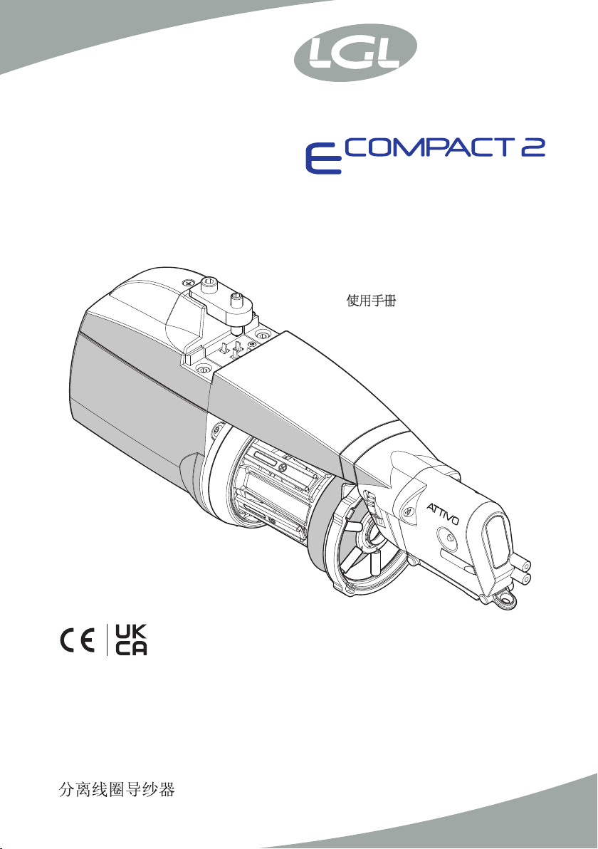
The ECOMPACT2 is a yarn feeder featuring separate coils, suitable for all types of knitting
machines or for textile machines requiring yarn feed-in with constant tension.
Optimised operation is provided with yarn counts ranging from 600 den (the thicker yarn
counts) down to 5 den (fine yarn counts).
IMPROPER uses
Improper uses are all those uses which are not expressly indicated among the design uses, namely:
- Working of yarns other than those specified
- Power supply of the machine not matching the specified value
- Use of the machine in an explosive atmosphere.
Operational features:
•Automatic speed adjustment designed to cover the machine’s yarn quantity requirements.
•Spool body winding reserve control by means of a magnetic feeler system.
•Yarn feeder and machine stop function if no yarn is detected at the feeder’s yarn input
(broken yarn or empty yarn bobbin).
•Kit KLS:
Feeder and machine stop function when no yarn is found on feeder outlet without using
mechanical sensors (yarn broken or out of the needles).
•The option of being able to fit on various tensioning devices based on the type of yarn
actually being used, at both the feeder’s inlet and outlet.
•Either vertical set-up or horizontal set-up assembly option, selectable based on requirements.
•Real-time detection and display function of the yarn consumption related to each machine feed
•ATTIVO electronic tensioner (optional). The operator sets the desired output tension, and
the system will maintain it, to avoid all tension changes depending on the yarn, the bobbin
and the like issues.
Technical specifications:
• Power supply by means of a direct connection with the machine, or through a power
supply box that is supplied separately by L.G.L. Electronics.
Power supply voltage data: V = 42-48 VAC three-phase Hz = 50/60 (AC version)
V = 57 VDC (DC version)
•Automatic yarn input speed control provided up to a maximum of 700 m/min.
•Coil separation feature fixed at 0,9 mm.
•Permanent magnet synchronous motor.
•Motor data:
Maximum power: 30 W
•Equivalent continuous A-weighted sound pressure level at maximum speed: <70 dB (A)
•Operation and storage conditions:
- Room temperature: from +10 to +40 °C
- Maximum humidity: 80%
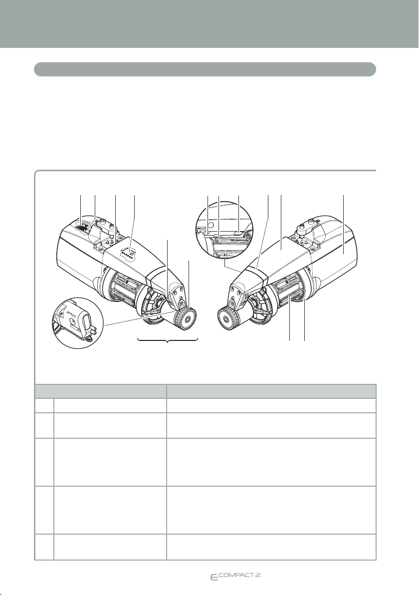
1.3 INTENDED USE TECHNICAL AND OPERATIONAL FEATURES
1 GENERAL FEATURES

11
1 GENERAL FEATURES 1 GENERAL FEATURES
Never pick the yarn feeder up by its yarn spool body, by its top panel or by
its tensioning unit.
The yarn feeder is supplied in an appropriate polystyrene casing; please store the casing for
use during any future handling.
The yarn feeder features an input feeler that provides the following function:
•“Machine stop” function:
this function stops both the feeder and
the machine if no yarn is detected at
feeder input (broken yarn or empty
yarn spool).
CAUTION: the machine will not
stop if the feeder comes to a
halt.
The machine stop signal is
operative only if the signal
lamps are ON.
1.4 HANDLING AND STORAGE INSTRUCTIONS
1.5 INPUT FEELER
input feeler
YES NO
1 GENERAL FEATURES

12
The optical sensor featured by the yarn feeder provides automatic speed adjustment based
on the quantity of yarn needed by the machine. For very fine yarn count processing (lower
than 40 den), the sensor requires DIP SWITCH settings (paragraph 2.4 refers).
The magnetic sensor that the yarn feeder is provided with has the function of monitoring the
yarn winding reserve on the spool body.
1 GENERAL FEATURES
1.6 OPTICAL OUTPUT SENSOR
1.7 YARN SPOOL BODY WINDING RESERVE CONTROL FEELER
Output sensor
(photocell)
Winding reserve
control feeler

13
1 GENERAL FEATURES
The assembly of this detection feeler onto the feeder output, enables the machine to
receive a stop signal that is relayed by the feeder when it detects output yarn snaps/
breaks.
IMPORTANT REMARK: the sensor can only be applied to specially pre-set
feeders, i.e. equipped with the dedicated cable duly built into the guard.
Installation: after fastening the sensor to the feeder by means of the screws and nuts provided
on the bracket, connect the board lead to the sensor.
1 GENERAL FEATURES
1.8 YARN OUTPUT DETECTION FEELER

14
N.B.: Yarn feeders that are moved from warehouse storage into a warmer
knitting mill environment may develop condensation; please wait until they
are completely dry before connecting them up.
Failure to do so may damage the electronic components.
For installation of the yarn feeder onto the machine, proceed as follows:
VERTICAL SET-UP VERSION
Fix the feeder onto the appropriate support plate (F) and fit in the power supply flat cable (G)
as well; tighten in grub screw (H) until the flat cable is punctured.
N.B.: The support ring shall be sized as follows:
- Height not less than 25mm
- Max thickness 10 mm
IMPORTANT: To avoid damaging the electronic components, the installation
sequence illustrated in the figures below must absolutely be complied with exactly.
The brown cable (I) must be kept facing the signal lamps (C) (if the flat cable is supplied by LGL,
the brown cable (I) can be identified by the arrows (L) printed on the flat cable).
N.B.: Make sure that the support plate the yarn feeder is fixed onto is
provided with an earth connection, the same goes for the 48V AC threephase
power supply transformer star-connection.
2 INSTALLATION AND STARTUP
2.1 YARN FEEDER INSTALLATION AND STARTUP (AC VERSION)
Brown
Yellow
Blue
Black
Grey flat
cable
Grey flat
cable
HF
G
LI
H
F
C
G
FC
G

15
2 INSTALLATION AND STARTUP
HORIZONTAL SET-UP VERSION
For installation of the yarn feeder onto the machine, proceed as follows:
- Fasten the clamp (F) with the screw (G) to the feeder; then block the clamp on the machine
pipe using the grub screw (H) that is found in the clamp, placing the feeder with the proper
inclination to operate.
F
H
H
AC DC
G

16
2 INSTALLATION AND STARTUP
- Connect up the feeders to the flat cable (I) by means of the appropriate locking plate (L)
then tighten it in with screw (M) located on the housing.
CAUTION: when connecting the flat cable, keep to the printed reference
marks showing the exact fixing position (the arrows (N) must point towards
the front end of the feeder).
Brown
Yellow
Blue
Black
Grey flat
cable
L
N
I
M

17
2 INSTALLATION AND STARTUP 2 INSTALLATION AND STARTUP
2.1.1 To be checked before switching power on (AC version)

18
2 INSTALLATION AND STARTUP
Be sure that the transformer is connected
to the correct primary voltage
Be sure that flat cables are connected to the
transformer with the correct color sequence
Blue
Black
Yellow
Brown

19
2 INSTALLATION AND STARTUP 2 INSTALLATION AND STARTUP
42-48 Vac
42-48 Vac
OK!

20
2 INSTALLATION AND STARTUP
For installation of the yarn feeder onto the machine, proceed as follows:
VERTICAL SET-UP VERSION
Fix the feeder onto the appropriate support plate (F) and fit in the power supply flat cable (G)
as well; tighten in grub screw (H) until the flat cable is punctured.
N.B.: The support ring shall be sized as follows:
- Height not less than 25mm
- Max thickness 10 mm
IMPORTANT: To avoid damaging the electronic components, the installation
sequence illustrated in the figures below must absolutely be complied with exactly.
The yellow/green cable (I) must be kept facing the signal lamps (C) (if the flat cable is supplied
by LGL, the yellow/green cable (I) can be identified by the arrows (L) printed on the flat cable).
N.B.: Ensure that the stand onto which the yarn feeder is fastened is electri-
cally grounded.
2.2 YARN FEEDER INSTALLATION AND STARTUP (DC VERSION)
Blue flat
cable
Blue flat
cable
Yellow/green
Brown
Blue
Red
LI
F
C
H
F
G
G
F
C
G
H
Table of contents
Popular Industrial Electrical manuals by other brands

Murata
Murata GRM0335C1E330JA01 Series Reference sheet

Murata
Murata GRM186R60J226ME15 Series Reference sheet

Furukawa electric
Furukawa electric FITELNINJA NJ001 Quick reference guide

Superior
Superior SD23 Operator's manual

HALE
HALE SmartFOAM 1.7AHP Description, Installation and Operation Manual

Murata
Murata GRM153D80J105ME95 Series Reference sheet