LIBERTY AV SOLUTIONS DIGITALINX DL-SC41U-TX User manual

Rev 200203 Phone: 719-260-0061
Toll-Free: 800-530-8998
Fax: 719-260-0075
DL-SC41U-TX Owners Manual
11675 Ridgeline Drive
Colorado Springs, CO
80921

DL-SC41U-TX Owners Manual
2
Important Safety Instrucons
»Please completely read and verify you understand all instrucons in this manual before operang this equipment.
»Keep these instrucons in a safe, accessible place for future reference.
»Heed all warnings.
»Follow all instrucons.
»Do not use this apparatus near water.
»Clean only with a dry cloth.
»Do not install near any heat sources such as radiators, heat registers, stoves, or other apparatus (including ampliers)
that produce heat.
»Use only accessories specied or recommended by Intelix.
»Explanaon of graphical symbols:
◊ Lightning bolt/ash symbol: the lightning bolt/ash and arrowhead within an equilateral triangle
symbol is intended to alert the user to the presence of uninsulated “dangerous voltage” within the
product enclosure which may be of sucient magnitude to constute a risk of shock to a person or
persons.
◊ Exclamaon point symbol: the exclamaon point within an equilateral triangle symbol is intended
to alert the user to the presence of important operang and maintenance (servicing) instrucons
in the literature accompanying the product.
»WARNING: TO REDUCE THE RISK OF FIRE OR ELECTRIC SHOCK, DO NOT EXPOSE THIS APPARATUS TO RAIN OR
MOISTURE AND OBJECTS FILLED WITH LIQUIDS, SUCH AS VASES, SHOULD NOT BE PLACED ON THIS APPARATUS.
»Use the mains plug to disconnect the apparatus from the mains.
»THE MAINS PLUG OF THE POWER CORD MUST REMAIN READILY ACCESSIBLE.
»Do not defeat the safety purpose polarized or grounding-type plug. A polarized plug has two blades with one wider
than the other. A grounding-type plug has two blades and a third grounding prong. The wide blade or the third prong
is provided for your safety. If the provided plug does not t into your outlet, consult an electrician for replacement of
your obsolete outlet. Cauon! To reduce the risk of electrical shock, grounding of the center pin of this plug must be
maintained.
»Protect the power cord from being walked on or pinched parcularly at the plugs, convenience receptacles, and the
point where they exit from the apparatus.
»Do not block the air venlaon openings. Only mount the equipment per Intelix’s instrucons.
»Use only with the cart, stand, table, or rack specied by Intelix or sold with the equipment. When/if a
cart is used, use cauon when moving the cart/equipment combinaon to avoid injury from p-over.
»Unplug this apparatus during lightning storms or when unused for long periods of me.
»Cauon! Shock Hazard. Do not open the unit.
»Refer to qualied service personnel. Servicing is required when the apparatus has been damaged in any way, such as
power supply cord or plug is damaged, liquid has been spilled or objects have fallen into the apparatus, the apparatus
has been exposed to rain or moisture, does not operate normally, or has been dropped.

DL-SC41U-TX Installaon Guide
3
Table of Contents
Product Overview��������������������������������������������������������������������������������������������������������������������������������������� 4
Product Contents���������������������������������������������������������������������������������������������������������������������������������������� 4
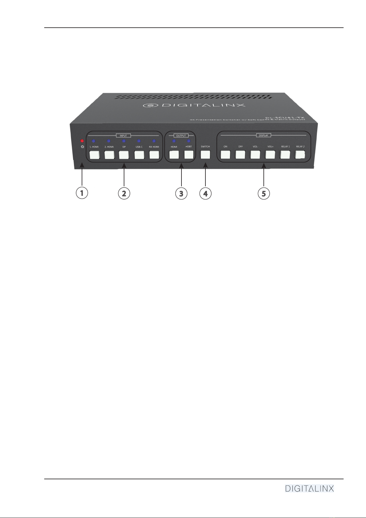
Front and Rear Panels��������������������������������������������������������������������������������������������������������������������������������� 5
Front Panel���������������������������������������������������������������������������������������������������������������������������������������������������� 5
Rear Panel����������������������������������������������������������������������������������������������������������������������������������������������������� 6
Installaon Instrucons������������������������������������������������������������������������������������������������������������������������������ 7
Mount the Matrix ����������������������������������������������������������������������������������������������������������������������������������������� 7
Connect Sources�������������������������������������������������������������������������������������������������������������������������������������������� 7
Video Inputs ........................................................................................................................................... 7
Connect Displays������������������������������������������������������������������������������������������������������������������������������������������� 7
HDMI Outputs ........................................................................................................................................ 7
HDBaseT Output (Oponal) .................................................................................................................... 7
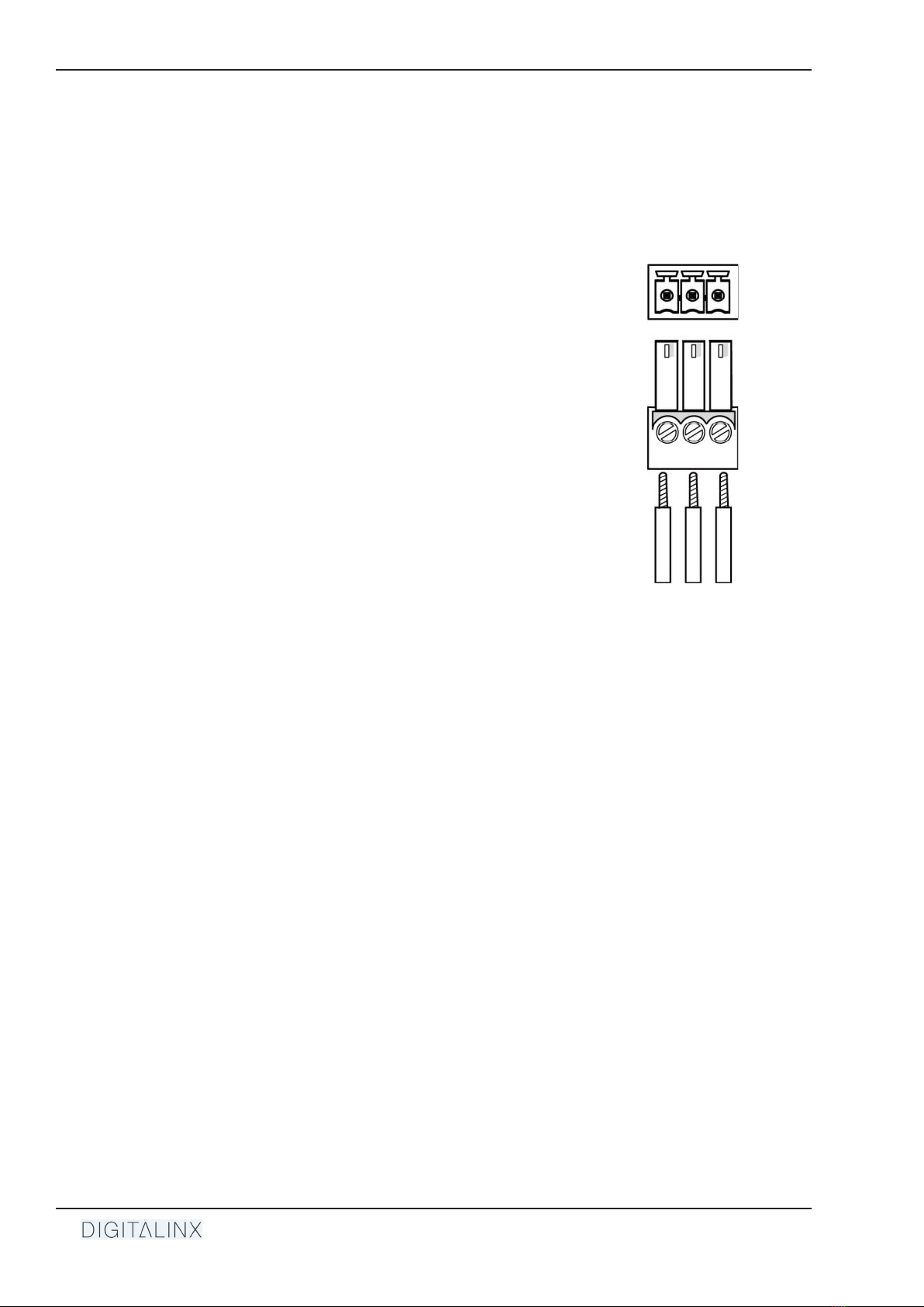
Connecng Control ��������������������������������������������������������������������������������������������������������������������������������������� 8
RS232 Port Wiring .................................................................................................................................. 8
Connect Ethernet (Web Browser) Control (Oponal) ������������������������������������������������������������������������������������ 9
Router Connecon ................................................................................................................................. 9
Crossover Cable Connecon ................................................................................................................... 9
Web Browser Control ............................................................................................................................. 9
Applying Power �������������������������������������������������������������������������������������������������������������������������������������������10
HDBaseT Cabling Requirements���������������������������������������������������������������������������������������������������������������� 10
A/V Diagram �������������������������������������������������������������������������������������������������������������������������������������������� 11
Standalone��������������������������������������������������������������������������������������������������������������������������������������������������11
With Oponal HDBaseT Receiver����������������������������������������������������������������������������������������������������������������12
Web GUI Control / System Sengs ����������������������������������������������������������������������������������������������������������� 13
Switcher Control������������������������������������������������������������������������������������������������������������������������������������������13
Connecng to Web GUI Control ...........................................................................................................13
A/V Switching .......................................................................................................................................14
RS232 Display Control Sengs .............................................................................................................15
Auto Display ON/OFF Sengs ..............................................................................................................16
USB Host Switching Sengs .................................................................................................................17
Edid Management ................................................................................................................................18
Relay Conguraon ..............................................................................................................................19
Renaming Inputs...................................................................................................................................20
Network Sengs ..................................................................................................................................21
Security Sengs ...................................................................................................................................22
System Sengs .....................................................................................................................................23
RS232 and TCP/IP Control ������������������������������������������������������������������������������������������������������������������������� 24
A/V Roung�������������������������������������������������������������������������������������������������������������������������������������������������24
USB Host Roung ����������������������������������������������������������������������������������������������������������������������������������������25
CEC / RS232 Display Control������������������������������������������������������������������������������������������������������������������������26
Relay Control�����������������������������������������������������������������������������������������������������������������������������������������������26
System Commands��������������������������������������������������������������������������������������������������������������������������������������27
Technical Specicaons ���������������������������������������������������������������������������������������������������������������������������� 28

DL-SC41U-TX Owners Manual
4
The DigitaLinx DL-SC41U-TX is a 4x1 mul format A/V presentaon auto switcher that supports video
resoluons up to 4K@60Hz 4:4:4 8bit deep color, is HDCP 2.2 compliant and has a built in USB 3.0
switching hub for control and integraon of USB devices such as USB cameras and microphones. The
switcher features four video inputs; (2) HDMI, (1) Display Port and (1) USB-C. The USB-C input supports
video, data (USB host) and power charging up to 40w. There is a 2 port USB client hub built with 2
USB host ports that can be switched independently or can be assigned to follow a video input so
when the video input is triggered or switched, the dened USB host port will also switch. The switcher
features two matrix outputs; HDMI and HDBaseT 2.0. The built in HDBaseT 2.0 transmier output
supports long distance transport of audio, video and High Speed USB 2.0 signals up to 190Mbps up to
70 meters / 232’ using one category cable. The switcher is compable with the DL-SCU-RX HDBaseT
2.0 receiver (sold separately) and the receiver can supply power to the DL-SC41U-TX remotely when
used in this conguraon. NOTE: When using the DL-SCU-RX HDBaseT 2.0 receiver, it will not provide
power charging to the USB-C input unless the DL-SC41U-TX is also powered.
The DL-SC41U-TX gives you the ability to automate the display power ON by using pre-loaded RS232
commands whenever a video signal is introduced to the system using any A/V input. It will also turn
the display power OFF aer a specied amount of me has passed when no video signal or switching
acvity is present. For a complete list of programming commands to automate display power status,
please see the complete owners manual online at www.libav.com or by using the QR code on the print
page of this guide.
The DL-SC41U-TX can be controlled via front panel buons or by API commands using RS232 or
Ethernet. A web server / GUI is built in that features A/V and USB switching control, automac display
control and input EDID management.
The DL-SC41U-TX is ideal for soware based video teleconference rooms that require the consolidaon
and sync of A/V and USB signals from a laptop or room PC.
NOTE: The DL-SC41U-TX switcher can be used as a standalone switcher or paired with an HDBaseT
receiver. The DL-SCU-RX HDBaseT 2.0 receiver (sold separately) is required to complete an extension
circuit. When using the DL-SCU-RX, only USB 2.0 Full Speed devices can be used on the receiver.
Product Overview
Product Contents
• DL-SC41U-TX 4X1 HDMI / USB Switcher
• (1) Quick Install Guide
• (1) 3 pin Phoenix Male Connector
• (4) Plasc Cushions
• (2) Mounng clips with 4 screws
• DC24V Power Supply with US, UK, EU and AU adapter plugs

DL-SC41U-TX Installaon Guide
5
Front and Rear Panels
Front Panel
123 4
1. POWER LED - Illuminated red when power is applied
2. INPUT - A/V source selector and input LEDs
• NOTE: The RX HDMI can only be used when paired with the DL-SCU-RX HDBaseT receiver
3. OUTPUT - Output selector and output LEDs
4. SWITCH - A/V switch selector
• To route an input to an output, select the INPUT, then the OUTPUT then press SWITCH. By
default the DL-SC41U-TX is set to auto switching mode.
5. DISPLAY - Display control buons, triggers CEC / RS232 commands
• ON: Turns display ON
• OFF: Turns display OFF
• VOL-: Turns display volume down
• VOL+: Turns display volume up
• RELAY 1: Turns relay 1 state ON/OFF
• RELAY 2: Turns relay 2 state ON/OFF
NOTE: The RELAY 1/2 buons can only be used when paired with the oponal DL-SCU-RX
HDBaseT receiver (not included)
Table of contents