LIBERTY AV SOLUTIONS DL-HD1X4-H2 User manual

www.libav.com 800.530.8998
USER MANUAL
1x4 w/ HDMI Loop Out
18G HDBaseT Distribution Amp / Splitter
DL-HD1X4-H2
Ver 1.0

USER MANUAL / DL-HD1X4-H2
2USER MANUAL / DL-HD1X4-H2 3
The DigitaLinx Series is a family of extension, routing, and switching products designed to allow digital
signals to extend beyond their limitations. Liberty’s latest addition, DL-HD1X4-H, is a complete kit that
comes with one 4K HDMI to HDBaseT distribution amplier plus four HDBaseT to HDMI receivers. This
extender kit allows for one HDMI signal to be sent to four dierent locations up to 150 meters away
while simultaneously passing the signal to a local display when using the loop output.
In addition to extending HDMI signals, enhanced features include:
Control: Pass bi-directional IR and RS232 control signals for communication to devices such as remote
displays, media players, or the distribution amplier.
Power: All receivers are powered using category cable, providing a clean and easy installation. The
provided power supply for the distribution amplier distributes the necessary power to all connected
receivers.
Audio: Extract the HDMI audio from the source content to digital or analog at the distribution amplier
in addition to analog found on any receiver to connect to any audio amplier or AV receiver.
Distance: Extend digital HDMI signals up to 120 meters away at resolutions reaching 4K2K@60Hz or
150 meters at 1080P@60Hz all from a signal CAT6/6a/7 cable.
Local Loop Output: Along with 4 HDBaseT outputs, the distribution amplier is equipped with 1 local
loop output for connecting to devices such as a local monitor for video preview or cascading the signal
to another Liberty DL-HD1X4-H distribution amplier increasing the outputs to 8 +1.
Advanced EDID Management: Take control of the EDID information that is being fed to the source device
so the system congures itself in a manner that meets your display requirements without needing to
best-match resolutions.
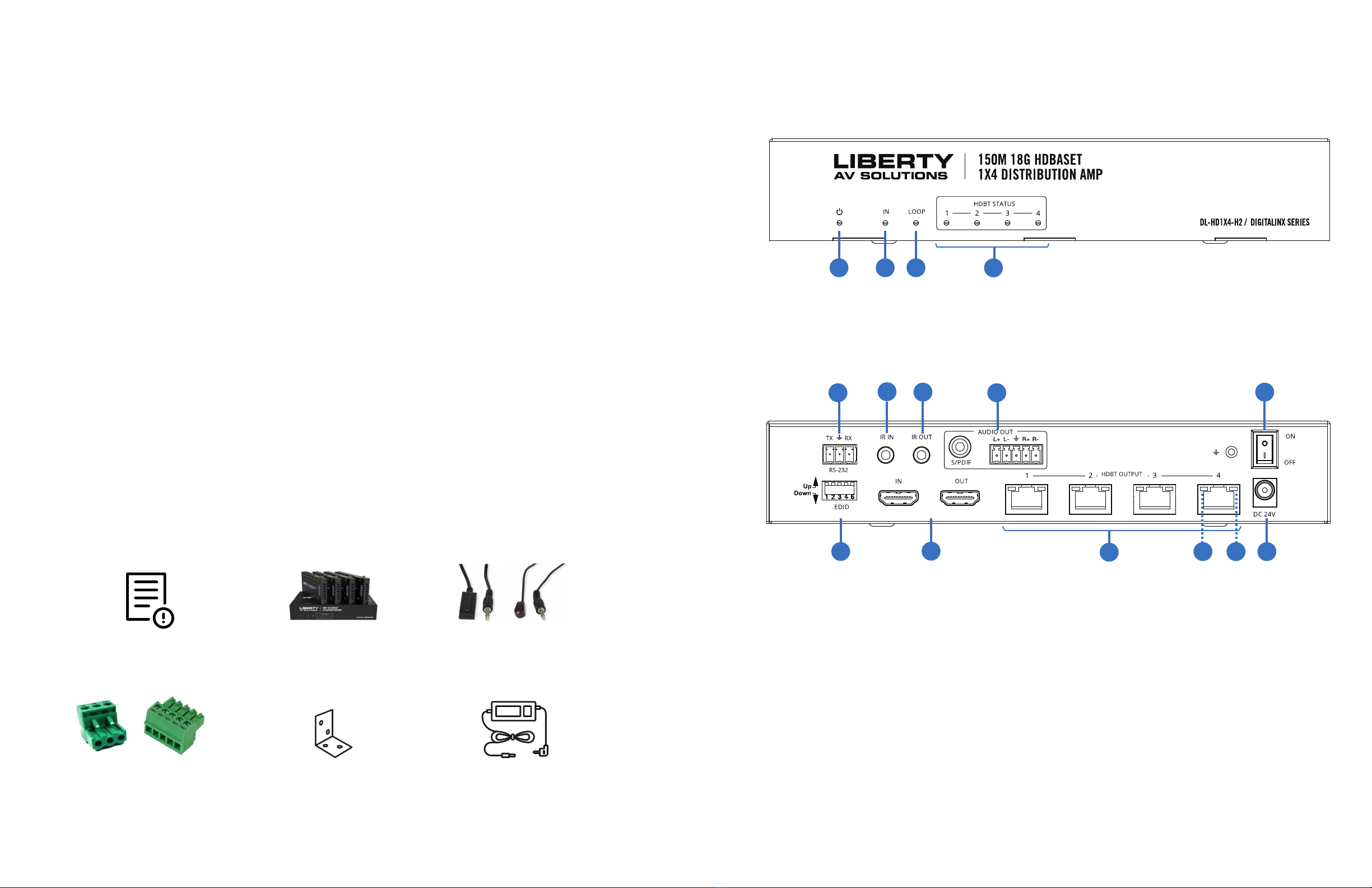
PRODUCT OVERVIEW
1. LED: POWER
2. LED: HDMI Input
1. 3-Pin phoenix female port. Pass control
signals to or from the main transmitter.
2. 3.5 female port. Connect IR BUD for sending
signals to devices such as third-party displays.
3. 3.5 female port. Connect IR Blaster for
receiving signals from party display locations.
4. Audio extraction ports: Female RCA port for
S/PDIF and 5-Pin phoenix connector.
5. Rocker switcher for power ON/OFF
6. EDID DIP switch for managing EDID settings:
See EDID conguration chart.
7. HDMI ports: Loop output and HDMI input
8. RJ45 female ports: HDBaseT signal extension
9. LED Link: Connection signal indicator lamp
(green)
10. LED data: data signal indicator lamp (orange)
11. Power port: DC 24V using the provided power
supply
Front Panel
Rear Panel
TRANSMITTER PRODUCT BREAKDOWN
PACKAGE CONTENTS
(x1) User Manual
(x5) 3-Pin Phoenix
Connector, (x1) 5-Pin
Phoenix Connectors
(x1) Transmitter, (x4)
HDBaseT Receivers
(x10) Mounting Ear
(x5) IR Blaster
Cables, (x5) IR
Receiver Cables
(x1) 24V/2.7A DC Locking
Power Supply with US, EU,
UK, AU Power Cords
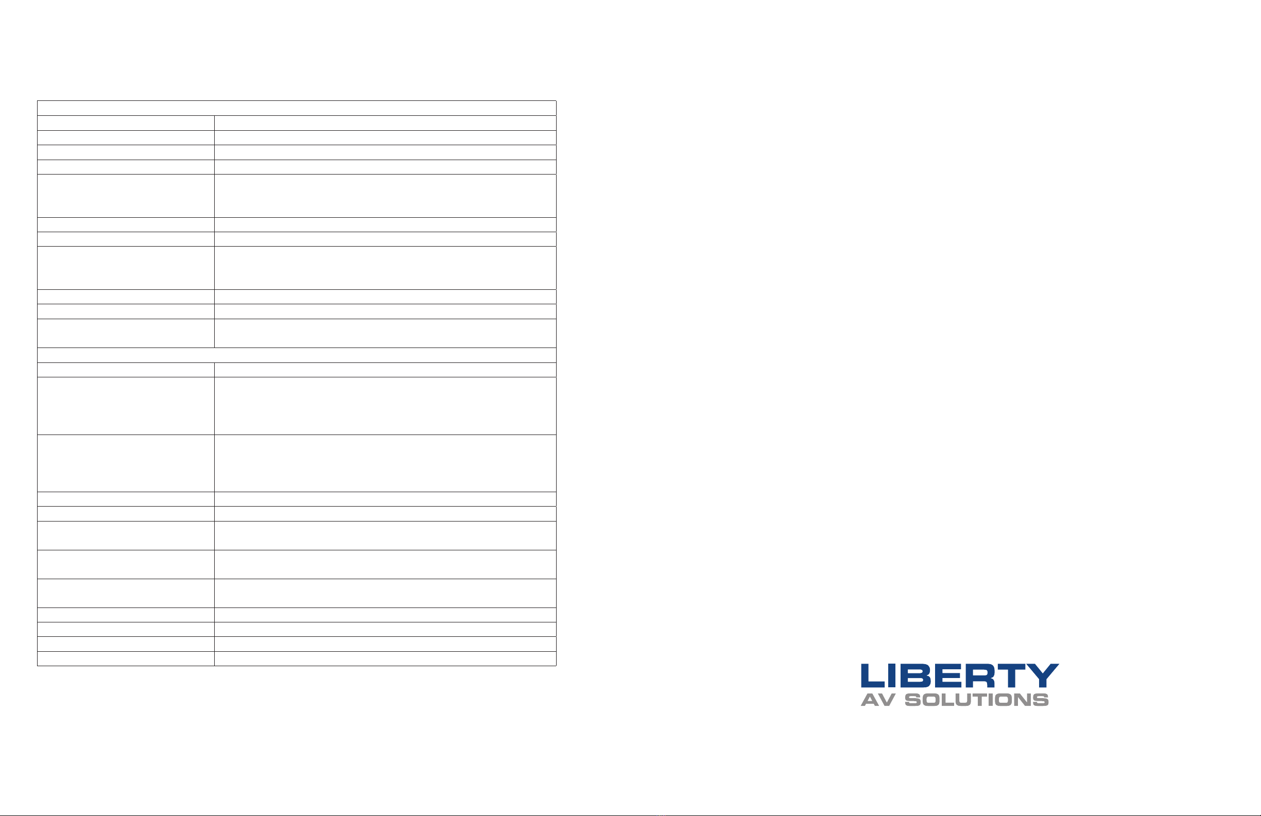
5. Operation Controls and Functions
Transmitter: 220mm (W) × 130mm (D) × 40mm (H)
Receiver: 140mm (W) × 65mm (D) × 18mm (H)
1
-3-
Power Supply
Dimensions
Weight Transmitter: 853g
Receiver: 246g
Housing Metal Enclosure
Silkscreen Color Black
Operation
Temperature 0°C ~ 40°C / 32°F ~ 104°F
Storage Temperature -20°C ~ 60°C / -4°F ~ 140°F
Relative Humidity 20~90% RH (non-condensing)
Power Consumption 35W
Mechanical
Input: AC100 - 240V 50/60Hz, Output: DC 24V/2.7A
(US/EU standards, CE/FCC/UL certified)
Front Panel
4
34
1/5
No. Name Function Description
1
2
3
4
POWER LED When the device is powered on, the red power LED will
be on.
IN LED When the HDMI IN port connects an active source device,
the green LED will be on.
HDBT STATUS
(1~4) LED
When the HDBT OUTPUT port connects an HDBaseT
Receiver, the corresponding green LED will be on.
LOOP LED When the HDMI LOOP OUT port connects an active
display device, the green LED will be on.
5.1 Transmitter
2 3
34
6
HDBT OUTPUT
port (1~4)
7
2
1
3
No. Name Function Description
1
2
3
4
Connect to the HDBT IN port of the HDBaseT receiver
with a CAT cable.
HDMI port
IN: HDMI input port, connect to HDMI source device such
as DVD or set-top box with an HDMI cable.
Rear Panel
67811
POWER switch Press this switch to power on/off the device.
-4-
EDID DIP
switch
Used to set EDID mode. Please refer to Section “6. EDID
Mode” for details.
AUDIO OUT
(S/PDIF, L/R)
Optical/balanced audio output port, connect to amplifer or
speaker.
OUT: HDMI loop output port, connect to the HDMI display
device such as TV or Monitor with an HDMI cable.
9 10
4
5
RS-232
IR IN Connect to IR receiver cable, the IR receive signal will
emit to “IR OUT” port of the HDBaseT Receiver.
IR OUT Connect to IR blaster cable, the IR emit signal is from “IR
IN” port of the HDBaseT Receiver.
5
8
9
Connect to a PC or control system via a 3-pin phoenix
connector cable for three functions:
1, Firmware update;
2, Control the Splitter via RS-232 commands;
3, RS-232 signal pass-through (from transmitter to
receiver or from receiver to transmitter).
▪ Illuminating: Transmitter and Receiver are in good
connection status.
▪ Flashing: Transmitter and Receiver are in poor
connection status.
▪ Dark: Transmitter and Receiver are not connected.
Connection
Signal Indicator
lamp (Green)
3. LED: HDMI LOOP Output
4. LED: HDBaseT STATUS indicator for outputs 1-4

USER MANUAL / DL-HD1X4-H2
4USER MANUAL / DL-HD1X4-H2 5
1. LED: Power indicator
2. Female micro USB port: *conguration
3. Female barrel port: DC 24V
4. RJ45 female port: HDBaseT input
from main transmitter
5. LED: Connection Signal Indicator lamp (green)
6. LED: Data signal indicator lamp (orange)
7. Female HDMI port: Output to a display device
8. Female 3.5 jack: Audio output to a audio device
9. IR IN
10. IR OUT
11. 3-Pin phoenix female port. Pass control signals
to or from the main transmitter.
DC 24V
Plug the DC 24V power supply into the unit and connect
the adaptor to an AC outlet. (Note: The transmitter can
power the receiver via a CAT cable.)
5.2 HDBaseT Receiver
-5-
HDBT IN Connect to the HDBT OUTPUT port on the transmitter
with a CAT cable.
HDMI OUT HDMI output port, connect to HDMI display device such
as TV or Projector with an HDMI cable.
No. Name Function Description
1
2
3
Power Indicator When the receiver is powered on, the power indicator will
be on.
4
CONFIG port Used for firmware update.
7
DC 24V
Plug DC 24V/1A power supply into the unit and connect
the adapter to an AC outlet.
(Note: The HDBaseT receiver also can be powered by the
transmitter via a CAT cable.)
10
11
IR IN IR OUT
HDMI OUT
DC 24V
HDBT IN
AUDIO OUT
1 2
3 104 117 8 9
Data Signal
Indicator lamp
(Orange)
▪ Illuminating: HDMI signal with HDCP.
▪ Flashing: HDMI signal without HDCP.
▪ Dark: No HDMI signal.
Connection
Signal Indicator
lamp (Green)
Data Signal
Indicator lamp
(Orange)
5
6
▪ Illuminating: Transmitter and Receiver are in good
connection status.
▪ Flashing: Transmitter and Receiver are in poor
connection status.
▪ Dark: Transmitter and Receiver are not connected.
▪ Illuminating: HDMI signal with HDCP.
▪ Flashing: HDMI signal without HDCP.
▪ Dark: No HDMI signal.
5 6
Note for extending IR signals: When the angle between the IR receiver and the remote control is ±
45°, the transmission distance is 0-5 meters; when the angle between the IR receiver and the remote
control is ± 90 °, the transmission distance is 0-8 meters.
RECEIVER PRODUCT BREAKDOWN APPLICATION EXAMPLE

USER MANUAL / DL-HD1X4-H2
6USER MANUAL / DL-HD1X4-H2 7
CONTROL PIN OUTS
RS232 Pass-Through Pinout
IR IN Connect to the IR Receiver cable. The IR signal will send
to the IR OUT port of the transmitter.
8
9
5.3 IR Pin Definition
-6-
IR Receiver IR Blaster
IR Blaster
IR Receiver
IR Blaster Signal
Power
NC
IR Signal
Power
Grounding
AUDIO OUT Audio output port, connect to amplifer or speaker.
IR OUT Connect to the IR blaster cable, the IR signal is from IR
IN port of the transmitter.
10
11 RS-232
3-pin Phoenix connector for RS-232 command
transmission. The RS-232 command will pass-through
from transmitter to receiver or from receiver to transmitter.
Note: When the angle between the IR receiver and the remote control is ± 45 °, the
transmission distance is 0-5 meters; when the angle between the IR receiver and the
remote control is ± 90 °, the transmission distance is 0-8 meters.
IR Receiver IR Blaster
IR Blaster
IR Receiver
ASCII COMMANDS
ASCII Commands
Serial port protocol. Baud rate: 115200, Data bits: 8bit, Stop bits:1, Check bit: 0
x - Parameter 1
y - Parameter 2
! - Delimiter
Command Code Function Description Example Feedback Default
Setting
Power
s power z! Power on/o the device,
z=0~1 (z=0 power o, z=1
power on)
s power 1! Power on
System Initializing...
Initialization Finished!
FW version x.xx.xx
power on
r power! Get current power state r power! power on/power o N/A
s reboot! Reboot the device s reboot! Reboot…
System Initializing...
Initialization Finished!
FW version x.xx.xx
N/A
System Setup
help! List all commands help! N/A N/A
r type! Get device model r type! HDC-SPB14H150 N/A
r status! Get device current status r status! Get the unit all status:
power, in/out
connection, EDID mode
N/A
r fw version! Get Firmware version r fw version! MCU BOOT: Vx.xx.xx
MCU APP: Vx.xx.xx
N/A
r link in! Get the connection status of
the input port
r link in! HDMI IN: connect N/A
r link out y! Get the connection status
of the y output port,
y=0~5(0=all, 1~4=HDBT 1~4, 5
= loop out)
r link out 1! HDMI loop out: connect
HDBT output 1: connect
N/A
s reset! Reset to factory defaults s reset! Reset to factory defaults
System Initializing...
Initialization Finished!
FW version x.xx.xx
N/A
Audio Pinout

USER MANUAL / DL-HD1X4-H2
8USER MANUAL / DL-HD1X4-H2 9
Command Code Function Description Example Feedback Default
Setting
Output Setting
s HDMI stream z! Set HDMI loop output
stream on/o z=0~1
(0:disable, 1:enable)
s HDMI
stream 1 !
Enable HDMI loop out stream
Disable HDMI loop out stream
enable
s HDMI hdcp z! Set HDMI loop output
hdcp on/o z=0~1
(0:disable, 1:enable)
s HDMI
hdcp 1!
Enable HDMI loop out hdcp
Disable HDMI loop out hdcp
enable
s HDBT y hdcp z! Set HDBT output y hdcp
on/o, y=0~4(0=all)
z=0~1(0:disable, 1:enable)
s HDBT 1
hdcp 1 !
s HDBT 0
hdcp 1 !
Enable HDBT output 1 hdcp
Disable HDBT output 1 hdcp
Enable HDBT all outputs hdcp
Disable HDBT all outputs hdcp
enable
s HDBT y stream
z!
Set HDBT output y stream
on/o, y=0~4(0=all) z=0~1
(0:disable, 1:enable)
s HDBT 1
stream 1 !
s HDBT 0
stream 1 !
Enable HDBT output 1 stream
Disable HDBT output 1 stream
Enable HDBT all outputs
stream
Disable HDBT all outputs
stream
enable
r HDMI stream! Get HDMI loop out
stream status
r HDMI
stream!
Enable HDMI output stream N/A
r HDMI hdcp! Get HDMI loop out hdcp
status
r HDMI
hdcp!
Enable HDMI output hdcp N/A
r HDBT y hdcp! Get HDBT output y hdcp
status, y=0~4(0=all)
r HDBT 1
hdcp!
Enable HDBT output 1 hdcp N/A
r HDBT stream! Get HDBT output
y stream status,
y=0~4(0=all)
r HDBT 1
stream!
Enable HDBT output 1 stream N/A
RS-232 BYPASS Setting
s rs232 bypass
HDBT y!
Set RS-232 port connect to
HDBT out1 Receiver RS-232
port, y=0~5( 0=all, 1~4= HDBT
out 1~4 5=NC)
s rs232
bypass
HDBT 1!
RS-232 connect to HDBT
OUT1
RS-232 not connect
to HDBT OUT
y=0
r rs232 bypass! Get RS-232 port connect to
HDBT out receiver RS-232 port
r rs232
bypass!
RS-232 connect to HDBT
OUT1
RS-232 connect to all
HDBT OUT
RS-232 not connect
to HDBT OUT
N/A
s device baud
w size x stop y
parity z!
Set receiver control device
COM port setting, w=2400,
4800,9600,19200,38400,
57600,115200, x=7,8 y=1,2,
z=none, even,odd
s device
baud 57600
size 8 stop 1
parity none!
receiver device COM
port setting baudrate:
57600 data size :8,
stop:1 parity: none
N/A
s rs232 time x! set send RS232 command wait
time x=200~5000ms
s rs232 time
200!
send RS-232 command
wait time 200ms
200ms
Command Code Function Description Example Feedback Default
Setting
EDID Setting
s EDID in from z! Set input EDID from default
EDID z, z=1~27
1, 1080p,Stereo Audio 2.0
2, 1080p,Dolby/DTS 5.1
3, 1080p,HD Audio 7.1
4, 1080i,Stereo Audio 2.0
5, 1080i,Dolby/DTS 5.1
6, 1080i,HD Audio 7.1
7, 3D,Stereo Audio 2.0
8, 3D,Dolby/DTS 5.1
9, 3D,HD Audio 7.1
10, 4K2K30_444,
Stereo Audio 2.0
11, 4K2K30_444,Dolby/DTS 5.1
12, 4K2K30_444,HD Audio 7.1
13, 4K2K60_420,
Stereo Audio 2.0
14, 4K2K60_420,
Dolby/DTS 5.1
15, 4K2K60_420,HD Audio 7.1
16, 4K2K60_444,
Stereo Audio 2.0
17, 4K2K60_444,
Dolby/DTS 5.1
18, 4K2K60_444,HD Audio 7.1
19, 4K2K60_444,
Stereo Audio 2.0 HDR
20, 4K2K60_444,
Dolby/DTS 5.1 HDR
21, 4K2K60_444,
HD Audio 7.1 HDR
22, copy from HDMI loop out
23, copy from HDBT output 1
24, copy from HDBT output 2
25, copy from HDBT output 3
26, copy from HDBT output 4
27, use user1 EDID
s EDID in
from 1!
input EDID:1080p,
Stereo Audio 2.0
Please toggle EDID
dip switch to 00000!
1080p,
Stereo
Audio
2.0
s EDID user1 00
FF FF FF FF …!
Set user1 EDID data s EDID user1
00
…. !
user1 EDID data: 00 FF
FF ….
N/A
r EDID user1! Get user1 EDID data r EDID user1! user1 EDID data : 00 FF
FF FF FF FF FF 00 ………
N/A
r EDID in! Get EDID status of the input r EDID in! input EDID: 4K2K60_
444,Stereo Audio 2.0
N/A
r EDID in data! Get the EDID data of the HDMI
input
r EDID in
data!
EDID data : 00 FF FF FF
FF FF FF 00 ……
N/A
ASCII COMMANDS CONT. ASCII COMMANDS CONT.

USER MANUAL / DL-HD1X4-H2
10 USER MANUAL / DL-HD1X4-H2 11
CONFIGURATION SETTINGS
LED FUNCTION STATUS
Status When the receiver is powered on, the red LED
light is on
Link • Illuminang: Transmier and receiver are in good connecon status.
• Flashing: Transmier and receiver are in poor connecon status.
• Dark: Transmier and receiver are not connected
Data • Illuminang: HDMI signals with HDCP.
• Flashing: HDMI signals without HDCP.
• Dark: No HDMI signals.
Power When the transmier is powered on, the red LED
light is on
HDMI When the HDMI input port is acve and the HDMI
signal is detected, the green LED light is on
DIP SWITCH EDID STATUS DESCRIPTION
11111 1080P, Stereo Audio 2.0
11110 1080P, Dolby/DTS 5.1
11101 1080P, HD Audio 7.1
11110 1080I, Stereo Audio 2.0
11011 1080I, Dolby/DTS 5.1
11010 1080I, HD Audio 7.1
11001 1080P 3D, Stereo Audio 2.0
11000 1080P 3D, Dolby/DTS 5.1
10111 1080P 3D, HD Audio 7.1
10110 4K2K30Hz_444, Stereo Audio 2.0
10101 4K2K30Hz_444, Dolby/DTS 5.1
10100 4K2K30Hz_444, HD Audio 7.1
10011 4K2K60Hz_420, Stereo Audio 2.0
10010 4K2K60Hz_420, Dolby/DTS 5.1
10001 4K2K60Hz_420, HD Audio 7.1
10000 4K2K60Hz_444, Stereo Audio 2.0
01111 4K2K60Hz_444, Dolby/DTS 5.1
01110 4K2K60Hz_444, HD Audio 7.1
01101 4K2K60Hz_444, Stereo Audio 2.0 HDR
01100 4K2K60Hz_444, Dolby/DTS 5.1 HDR
01011 4K2K60Hz_444, HD Audio 7.1HDR
01010 COPY_FROM_LOOP OUT
01001 COPY_FROM_HDBT OUT1
01000 COPY_FROM_HDBT OUT2
00111 COPY_FROM_HDBT OUT3
00110 COPY_FROM_HDBT OUT4
00101 1080P, Stereo Audio 2.0
00100 1080P, Stereo Audio 2.0
00011 1080P, Stereo Audio 2.0
00010 1080P, Stereo Audio 2.0
00001 1080P, Stereo Audio 2.0
00000 PC control mode
CONFIGURATION SETTINGS CONT.

USER MANUAL / DL-HD1X4-H2
12
Thank you for your purchase.
For technical support please call our
toll-free number at 800-530-8998
www.libav.com 800-530-8998
TECHNICAL SPECIFICATIONS
Technical
HDMI Compliance HDMI 2.0b
HDCP Compliance HDCP 2.2/1.x
Video Bandwidth 594MHz/18Gbps
Video Resolution Up to 4k2k@60Hz 4:4:4
Color Depth 8-bit,10-bit,12-bit(1080p@60Hz)
8-bit (4K2K@60Hz YUV4:4:4)
8-bit,10-bit,12-bit(4K2K@60Hz YCbCr 4:2:2/4:2:0)
Color Space RGB 4:4:4, YCbCr 4:4:4 / 4:2:2 / 4:2:0
HDR Support HDR, HDR10+, HLG, Dolby vision
HDMI Audio Formats LPCM 2.0/2.1/5.1/6.1/7.1, Dolby Digital, Dolby TrueHD,
Dolby Digital Plus(DD+), DTS-ES, DTS HD Master,
DTS HD-HRA, DTS-X
Coaxial Audio Formats PCM2.0, Dolby Digital / Plus, DTS 2.0/5.1
Analog Audio Formats PCM 2.0CH
ESD Protection Human body model—±8kV (Air-gap discharge) & ±4kV
(Contact discharge)
Connection
Input 1×HDMI Type A (19-pin female)
Output 1×HDMI Type A (19-pin female)
4x HDBaseT OUT [RJ45]
1x Coaxial Audio OUT [RCA]
1x L/R Audio OUT [5-pin phoenix connector]
Control 1×RS-232 (3-pin phoenix connector)
1x EDID DIP switch [5-pin]
1x IR IN [3.5mm Stereo Mini-jack]
1x IR OUT [3.5mm Stereo Mini-jack]
Housing Metal Enclosure
Silkscreen Color Black
Dimensions Transmitter: 220mm (W) × 130mm (D) × 40mm (H)
Receiver: 140mm (W) × 65mm (D) × 18mm (H)
Weight Transmitter: 853g
Receiver: 246g
Power Supply Input: AC100 - 240V 50/60Hz, Output: DC 24V/2.7A
(US/EU standards, CE/FCC/UL certied)
Power Consumption 35W
Operation Temperature 0°C ~ 40°C / 32°F ~ 104°F
Storage Temperature -20°C ~ 60°C / -4°F ~ 140°F
Relative Humidity 20~90% RH (non-condensing)
Table of contents