LIBRO CB55 User manual
USER MANUAL
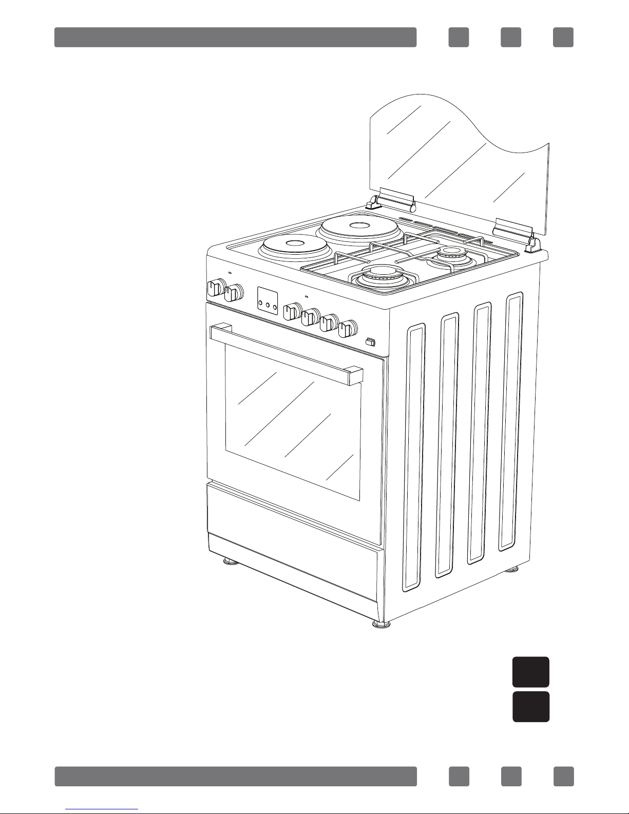
FREE STANDING OVEN
50x55 / 50x60 / 60x60
Gas & Electrical Oven
H10-20-180-039 Rev 002
GUIA DEL USUARIO ES
GB

2
Dear User,
Our objective is to make this product provide you with the best output
which is manufactured in our modern facilities in a careful working envi-
ronment, in compliance with total quality concept.
Therefore, we suggest you to read the user manual carefully before us-
ing the product and, keep it permanently at your disposal.
Note: This user manual is prepared for more than one model. Some of
the features specied in the Manual may not be available in your appli-
ance.
All our appliances are only for domestic use, not for commercial use.
“THIS APPLIANCE SHALL BE INSTALLED IN ACCORDANCE WITH THE
REGULA TIONS FORCE AND ONLY USED IN A WELL VENTILATED SPACE. READ
THE INSTRUCTIONS BEFORE INSTALLING OR USING THIS APPLIANCE”
“Conforms with the EEE Regulations."
GB

3
CONTENTS
Important warnings 4
Introduction of the Appliance 6
Important warnings 7
Chain Lashing Illustration 8
Installation of your oven 9
Technical features of your oven 9
If the appliance does not operate 11
Control panel 12
Using cooker section 12
Using oven section 14
Maintenance and cleaning 15
Installation of the Oven Door 16
Cleaning and maintenance of the
oven’s front door glass 17
Changing the Oven Lamp 17
Accessories 18
Nozzle change operation 19
Reduced ame gas cock adjustment 19
Removal of the Lower and Upper Burner and
Installation of the Injector to the Gas Oven 20
GB

4
IMPORTANT WARNINGS
1.Pay attention to minimum health and safety requirements.
2.The cooker is supplied setup according to the conditions shown on the
rating label which is stuck to the rear of the appliance. From this sticker
you can learn for which gas type (LPG or NG) this appliance is congured
when supplied.
3.Keep the electrical cable of your oven away from the hot areas.
4.If the supply cord is damaged, it must be replaced by the manufactur-
er its services agent or similar qualied persons in order to avoid hazard.
5.Ensure that the appliance is switches off before replacing the lamp to
avoid the possibility of electric shock.
6.In case of power failure, readjust your timer denitely. Otherwise, the
oven will not operate (Digital Timer).
7.Your oven can be having different output pressure according your
countries gas and pressure specications. Be sure that the cooker is con-
gured correctly for local requirements (for example, the jets must be
suitable for local gas type and gas pressure).
8.Connect your oven to LPG in shortest way and without any leakage.
Min. 40 cm Max. 125 cm.
9.When making gas leakage check, never use any ame type like those
of lighter, matches, cigarette re or similar ones.
10.Usage of your appliance creates moisture and heath in the room it
is placed, make sure that your kitchen is ventilated well. Maintain the
natural ventilation ducts properly.
11.CAUTION! Do not touch hot parts with bare hands and keep children
well supervised
12.When the oven is hot never touch the oven glass by hand.
13.Before starting to use your appliance, keep curtain, tulle, paper or
inammable things away from your appliance. Do not keep combustible
or inammable things in or on the appliance.
GB

5
14.This appliance is for cooking purposes only. It must not be used for
other purposes, for example room heating. All our appliances are only for
domestic use, not for commercial use.
15.For disconnection from the supply mains having a contact separation
in all poles that provide full disconnection, must be incorporated in xed
wiring in accordance with the wiring rules.
16.Some models are supplied without a plug-an-lead set. In this
case please use a exible cable to suitable for connection to mono
phase: H05 VV-F3G4mm 2 or for 3 phase: H05 VV-F 5G 1.5mm 2
17.This appliance is produced in accordance with the safety regula-
tions. Incorrect use will harm people and appliance.
18.Children should be supervised to ensure that they do not play with
the appliance. Never let them play with the appliance.
19.Unattended cooking on a hob with fat or oil can be dangerous and
may result in re.NEVER try to extinguish a re with water, but switch off
the appliance and then cover ame e.g. with a lid or a re blanket.
20.Danger of re: do not store items on the cooking surfaces
21.This appliance is not intended for use by persons (including chil-
dren) with reduced physical, sensory and mental capabilities or lack of
experience and knowledge, unless they have been given supervision or
instruction concerning the use of the appliance by a person responsible
for their safety.
22.“CAUTION: Accessible parts may be hot when the grill is in use. Young
children should be kept away”
GB
6
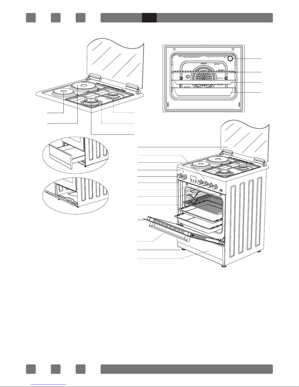
1. Hotplate Ø145mm
2. Hotplate Ø185mm
3. Middle Burner
4. Trivet
5. Large Burner
6. Glass Door (Sheet Metal
Door)
7. Cooker Section Led Lamp
8. Oven Section Led Lamp
9. Control Panel
10. Thermostat Setting
11. Oven Setting
12. Digital Timer
13. Cooker Section Control
Switches
14. Push Button Lighter
15. Door
16. Handle
17. Plastic Leg
18. Lower Cabinet
Door
18.1 Drawer
18.2 Flap Door
19. Lamp
20. Grill
21. Standard Tray
22. Deep Tray
19
20
21
22
INTRODUCTION OF THE APPLIANCE
6
7
8
9
10
11
18
17
16
15
14
13
12
3
4
5
2
1
18.2*
18.1*
Figure 18.1 and 18.2 are op-
tional for ovens with dimen-
sions 50x60 and 60x60(*)
Figure 18.1 is not available for
oven with dimension 50x55
and 18.2 is optional. (*)
GB

7
IMPORTANT WARNINGS
Electrical Connection and Security
1.Your oven requires 16 or 32 Ampere fuse according to the appliance’s
power. If necessary, installation by a qualied electrician is recommended.
2.Your oven is adjusted in compliance with 230V~50-60Hz. (or-
230V/400V~50-60Hz.) electric supply. If the mains are different from
this specied value, contact your authorized service.
3.Electrical connection of the oven should only be made by the sockets
with earth system installed in compliance with the regulations. If there
is no proper socket with earth system in the place where the oven will be
placed, immediately contact a qualed electrician. Manufacturer shall
never be responsible from the damages that will arise because of the
sockets connected to the appliance with no earth system. If the ends of
the electrical connection cable are open, according to the appliance type,
make a proper switch installed in the mains by which all ends can be
disconnected in case of connecting / disconnecting from / to the mains.
4.If your electric supply cable gets defective, it should denitely be re-
placed by the authorized service or qualed electricians in order to avoid
from the dangers.
5.Electrical cable should not touch the hot parts of the appliance.
6.Please operate your oven in dry atmosphere.
Gas Connection and Security
Please operate your oven in dry atmosphere.
1.Fit the clamp to the hose. Push one of the hose until it goes to the
end of the pipe.
2.For the sealing control; ensure that the buttons in the control panel
are closed, but the gas cylinder is open. Apply some soap bubbles to the-
connection. If there is gas leakage, there will be foaming in the soaped
area.
3.The oven should be using a well ventilation place and should be in-
stall on at ground.
4.Re-inspect the gas connection.
5.When placing your oven to its location, ensure that it is at the counter
level. Bring it to the counter level by adjusting the feet if necessary.
6.Do not make gas hose and electrical cable of your oven go through
theheated areas, especially through the rear side of the oven. Do not move
gas connected oven. Since the forcing shall loosen the hose, gas leakage
may occur.
7.Before using the appliance, in order to ensure safe use, be sure to
GB
8
x the appliance to the wall using the chain and hooked screw supplied.
Ensure that the hook is screwed into the wall securely.
8.Please use exible hose for gas connection.
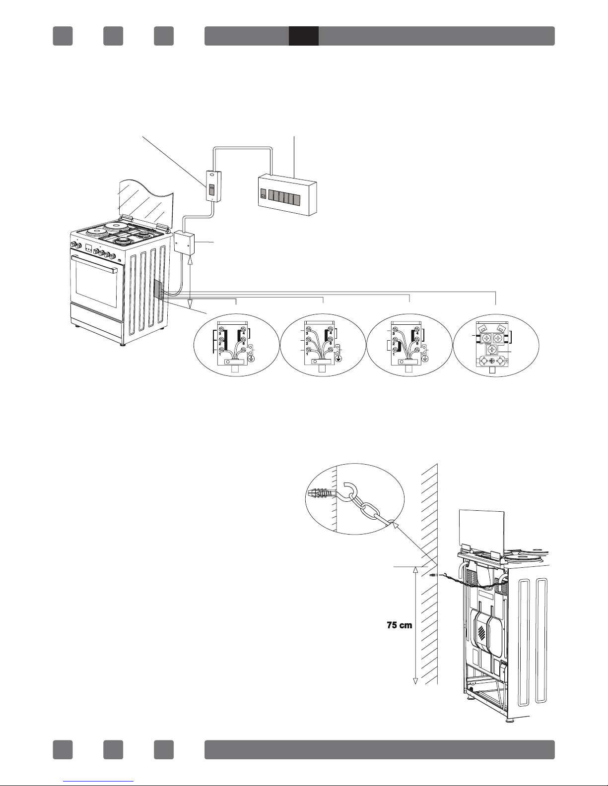
Before using the appliance, in order to
ensure safe use, be sure to x the appli-
ance to the wall using thechain and hooked
screw supplied. Ensure that the hook is
screwed into the wall securely.
Chain Lashing Illustration
230V~50-60Hz 230V~50-60Hz
400V 3N~50-60Hz 400V 2N~50-60Hz
Earth
Terre
Erdung
Earth
Terre
Erdung
Earth
Terre
Erdung
Earth
Terre
Erdung
L3
L2
L1
L2
L1
L1
Live
Phase
Neutral
Neutre Neutral
Neutre Neutral
Neutre
FUSE SWITCH (25A/40A)
JUNCTION BOX
3x4mm²
3x4mm²
610mm
H05 VV-F 3G 4mm² H05 VV-F 5G 1.5mm² H05 VV-F 4G 1.5mm² H05 VV-F 3G 1.5mm²
CONSUMER UNIT
Neutral
Neutre
GB

9
INSTALLATION OF YOUR OVEN
TECHNICAL FEATURES OF YOUR OVEN
SPECIFICATIONS 50x55 50x60 60x60
Outer width 500mm 500mm 600mm
Outer depth 565mm 630mm 630mm
Outer height 855mm 855mm 855mm
Inner width 341mm 341mm 441mm
Inner depth 443mm 443mm 443mm
Inner height 316mm 316mm 316mm
Inner volume 48lt 48lt 62lt
Lamp power 15W 15W 15W
Bottom heating element 1000W 1000W 1200W
Top heating element 800W 800W 1000W
Turbo heating element ----- 1800W 2200W
Grill heating element 1500W 1500W 2000W
850 mm min.
500 -600 mm min.
20 mm 20 mm
GB

10
Supply Voltage 220V-240V AC,50-60Hz (Or
230V400V AC,50-60 Hz)
Hot Plate 145 mm 1000 W
Hot Plate 180 mm 1500 W
Hot Plate rapid 145 mm 1500 W
Hot Plate rapid 180 mm 2000 W
BURNER INJECTOR VALUES
ACCORDING TO
THE GAS TYPE
LPG
G30/28-30 mbar NG
G20/20 mbar
NG
G25/25 mbar
Wok
Burner
Injector Ø mm 0,96 1,30 1,40
Power kW 3,60 3,35 3,66
Consuption
Gr/h,m³/h 259,20 0,300 0,365
Rapid
Burner
Injector Ø mm 0,85 1,15 1,15
Power kW 2,75 2,75 2,75
Consuption
Gr/h,m³/h 198 0,263 0,287
Semi
Rapid
Burner
Injector Ø mm 0,65 0,97 0,97
Power kW 1,60 1,70 1,70
Consuption
Gr/h,m³/h 115,20 0,165 0,175
Auxiliary
Burner
Injector Ø mm 0,50 0,72 0,72
Power kW 0,90 0,90 0,90
Consuption
Gr/h,m³/h 64,80 0,086 0,097
Oven
Burner
Injector Ø mm 0,65 0,97 0,97
Power kW 1,80 1,85 1,85
Consuption
Gr/h,m³/h 129,60 0,174 0,192
Grill
Burner
Injector Ø mm 0,60 0,92 0,92
Power kW 1,50 1,55 1,55
Consuption
Gr/h,m³/h 108 0,153 0,164
GB
This manual suits for next models
2
Table of contents
Languages:


