4
Circuit Diagnosis
LIFAN 630
2. Test Light with Self-supply and Ohmmeter
Use test light with own 12V power supply or
ohmmeter to test the circuit continuity. Test
light comprises a bulb, battery and a pair of
wires. The bulb will be lit when the two wires
contacted. Before test, disconnect the battery
negative and pull out the fuse of the circuit to
be tested. To test the circuit continuity,
contact two wires to the two measurement
points. If the bulb is lit, it means the circuit is
continuous.
Warning
DO NOT use test light with self-
supply to test the control module. To do
so, it could damage the circuit inside the
control module. Please use a ohmmeter
with 10M Ωor higher internal impedance.
Ohmmeter has the same usage method as
voltmeter, but ohmmeter can show the
impedance value. The lower impedance, the
better continuity.
3. Jumper with Fuse
Use jumper to test a broken point for open
loop circuit (circuit broken). The jumper
should be in tandem with the circuit to be
tested.
Warning
To protect the circuit, DO NOT
use the fuse with higher rated capacity
than the circuit to be tested. DO NOT use
the jumper as the input or output signal
when a control module like ECM, TCM is in
the circuit. To do so, it could damage the
circuit inside the control module.
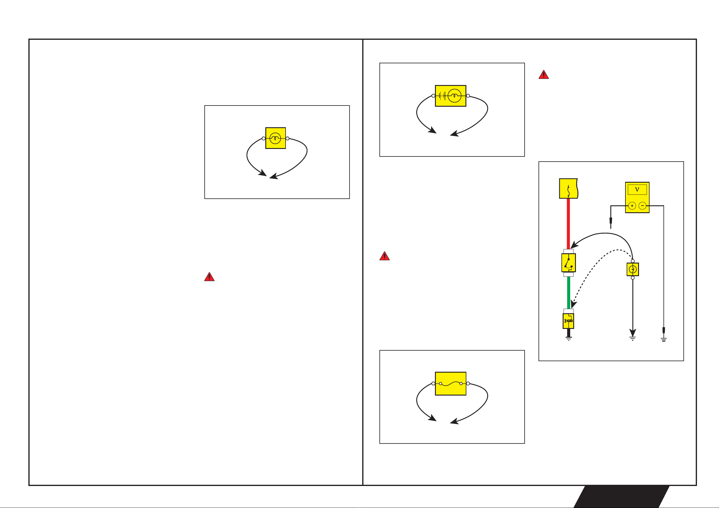
Fault Test
1. Voltage Test
Voltage test process is to test the voltage at a
certain point. When testing the connector
terminals, insert the positive probe into the
wire instead of breaking the harness.
1 When testing the voltage with test light or
voltmeter, connect the negative wire of
the test light or the negative probe of the
voltmeter to the ground.
2 Connect the other wire of the test light or
the positive probe of the voltmeter to the
place to be tested.
a1105002
5A
a1105003
I/P Fuse and Relay Box
Switch
Solenoid
Test Light
Voltmeter
5A
+B
0.5RD0.5G
2 E00
1E00
1C00
a1105022
Circuit Diagnostic Procedure
Refer to the following procedure for the circuit
diagnosis:
1. Confirm the Fault
To do the proper repair, confirm the fault
descibed by the customer firstly. Inspect the
relevant component carefully and make
record. DO NOT disassemble the component
before confirmation of the fault scope and
causes.
2. Read the Wiring Diagram and Analyze the
Causes.
Make a complete analysis on the faulty
components from power supply to ground
according to the sub-system wiring diagram
and determine the repair solution. If can not
determine the repair solution, please read the
system description in the “Description and
Operation” in the workshop manual to clear
the working principle. And inspect other
circuits that has common part with the faulty
circuit, for example, the fuse, ground, switch,
etc. Inspect the circuit not covered in step 1. If
other components on the common circuit
work properly, it means the fault exists in its
own circuit. Otherwise, the fuse or ground
might has faults.
3. Inspect the Circuits and Components.
Always use the wiring diagram together with
workshop manual and refer to the diagnostic
procedure for the relevant circuits or
components in the workshop manual. For the
circuit with a control module, fully use
diagnostic tools to do the test. Effective
diagnosis should be a logical and reasonable
operation. Fully use the diagnoistic
procedures in the workshop manual and start
the inspection from the most likely causes
and the compents be easiest to inspect.
4. Repair
Repair the faulty circuit. Refer to the wiring
diagram and workshop manual for fault
treatment. For example, the treatment on bad
connection to ground and the harness
connector.
5. Confirm the Fault Removed.
After repair, confirm the fault removed and all
functions work properly. For the fuse blown
fault, check all the relevant circuits.
Circuit Diagnostic Device
1. Voltmeter and Test Light
Use test light or voltmeter to check the circuit
status.
Test light comprises a pair of wires and a 12V
bulb. When inspecting, connect one wire to
the ground and the other one to the
measurement point. If the bulb is lit, it means
the measurement point has power supply.
Warning
DO NOT use test light to test the
control module voltage. To do so, it could
damage the circuit inside the control
module. Please use a voltmeter with 10M Ω
or higher internal impedance (e.g. to test
the ECM voltage.).
Voltmeter has the same connection method
as the test light, but voltmeter can display the
voltage value of the circuit. Use a voltmeter
with high impedance to test the voltage. If the
circuit has poor connection, the voltmeter
may show the normal value, but the voltage
can not drive the load successfully.
a1105001