Life technologies Invitrogen E-Gel 4466602 User manual

E-Gel® Imager Light/Adaptor Base
Cat. nos. 4466602, 4466603, 4466604
Rev. Date: 6 August 2011
Part no. 25-1072 MAN0004954
Intended Use
For research use only. Not intended for any animal or
human therapeutic or diagnostic use.
QUICK REFERENCE
E-Gel® Imager Adaptor Base
E-Gel® Imager Light Base
Catalog no. Components Quantity
4466602 E-Gel® Imager UV Light Base
Universal 12 V Power Cord
1
1
4466603 E-Gel® Imager Blue-Light Base
Universal 12 V Power Cord
1
1
4466604 E-Gel® Imager Adaptor Base
DC Connector Cable
1
1
Kit contents
ON/OFF
Power Button
Directions for installation of the E-Gel® Safe Imager™, E-Gel® iBase™ Device, and E-Gel®
Go! Base with the E-Gel® Imager UV/Blue-Light Base, or E-Gel® Imager Adaptor Base are
described below. For detailed instructions refer to the E-Gel® Imager Gel Documentation
System manual included in the software CD, or contact Technical Support.
E-Gel® Imager Adaptor Base Port
E-Gel® Imager Light Base Ports
48 V Power
Port
12 V Power
Port
48 V Power
Port
E-Gel ImagerBase.indd 1 8/10/2011 4:15:20 PM
All manuals and user guides at all-guides.com
all-guides.com

E-Gel® iBase™ with the E-Gel® Imager Light Base
The E-Gel® Imager Blue-Light Base
and E-Gel® Imager UV Light Base
can be used to provide transillumi-
nation for the E-Gel® iBase™.
For best results, afx the E-Gel®
Imager Light Diffuser to the bottom
of the E-Gel® iBase™ when using this
conguration.
Installing
the E-Gel®
iBase™ with
the E-Gel®
Imager
Light Base
Page 2
Installing
the E-Gel®
iBase™ with
the E-Gel®
Imager
Adaptor Base
DC Connector
Cable
1. Place the E-Gel® iBase™ directly onto the transilluminator surface of
the E-Gel® Imager Light Base.
2. Connect the DC Connector Cable between the E-Gel® iBase™ and the
E-Gel® Imager Adaptor Base.
3. Connect the E-Gel® iBase™ power supply cable to the 48 V power
port at the rear of the E-Gel® Imager Light Base.
4. The E-Gel® iBase™ Device is now ready for use with the E-Gel®
Imager system.
E-Gel® Imager
Adaptor Base
E-Gel® iBase™ Device
The E-Gel® Safe Imager™ can be
used with the E-Gel® Imager
Adaptor Base to provide
transillumination for imaging with
the E-Gel® iBase™ Device.
Note: Make sure to press the ON
button of the E-Gel® Safe Imager™.
for 2 seconds to extend the dura-
tion of transillumination.
Important: There are two types of
plug on the E-Gel® Safe Imager™.
Choose the appropriate
installation method for the E-Gel®
iBase™/E-Gel® Safe Imager™ based
on whether your E-Gel® Safe
Imager™ has Plug A, or Plug B.
Plug A
Plug B
E-Gel ImagerBase.indd 2 8/10/2011 4:15:23 PM
All manuals and user guides at all-guides.com

E-Gel® iBase™ with the E-Gel® Adaptor Base
1. Place the E-Gel® Safe Imager™
into the well of the E-Gel®
Imager Adaptor Base.
2. Connect the E-Gel® Safe Imager™
(Plug A) to the E-Gel® Imager
Adaptor Base.
Page 3
Plug A
Installation
Method
3. Connect the DC Connector Cable between the E-Gel® Safe Imager™
and the E-Gel® iBase™ Device.
4. Connect the E-Gel® iBase™ power supply cable to the 48 V power port
at the rear of the E-Gel® Imager Adaptor Base.
5. The E-Gel® iBase™ Device is now ready for use with the E-Gel®
Imager system.
1. Place the E-Gel® Safe Imager™ into the well of the E-Gel® Imager
Adaptor Base.
2. Connect the DC Connector Cable between the E-Gel® Safe Imager™
and the E-Gel® Imager Adaptor Base.
3. Connect the E-Gel® Safe Imager™ (Plug B) to the E-Gel® iBase™
Device.
Plug A
Plug B
DC Connector
Cable
E-Gel® Imager
Adaptor Base
E-Gel® iBase™ DeviceE-Gel® Safe Imager™
4. Connect the E-Gel® iBase™ power supply cable to the 48 V power port
at the rear of the E-Gel® Imager Adaptor Base.
5. The E-Gel® iBase™ Device is now ready for use with the E-Gel®
Imager system.
Plug B
Installation
Method
DC Connector
Cable
E-Gel® Imager
Adaptor Base
E-Gel® iBase™ Device
E-Gel® Safe Imager™
E-Gel ImagerBase.indd 3 8/10/2011 4:15:30 PM
All manuals and user guides at all-guides.com

E-Gel® Go! Base with the E-Gel® Adaptor Base
©2011 Life Technologies Corporation. All rights reserved. The trademarks mentioned herein are the property of Life
Technologies Corporation or their respective owners.
For technical support, email tech_support@invitrogen.com.
For country-specific contact information, visit www.invitrogen.com.
To reorder visit www.invitrogen.com
Limited Use Label License: Research Use Only: The purchase of this product conveys to the purchaser the
limited, non-transferable right to use the purchased amount of the product only to perform internal research
for the sole benet of the purchaser. No right to resell this product or any of its components is conveyed
expressly, by implication, or by estoppel. This product is for internal research purposes only and is not for use
in commercial services of any kind, including, without limitation, reporting the results of purchaser’s activities
for a fee or other form of consideration. For information on obtaining additional rights, please contact outli-
[email protected] or Out Licensing, Life Technologies, 5791 Van Allen Way, Carlsbad, California 92008.
Limited
Use Label
License
Page 4
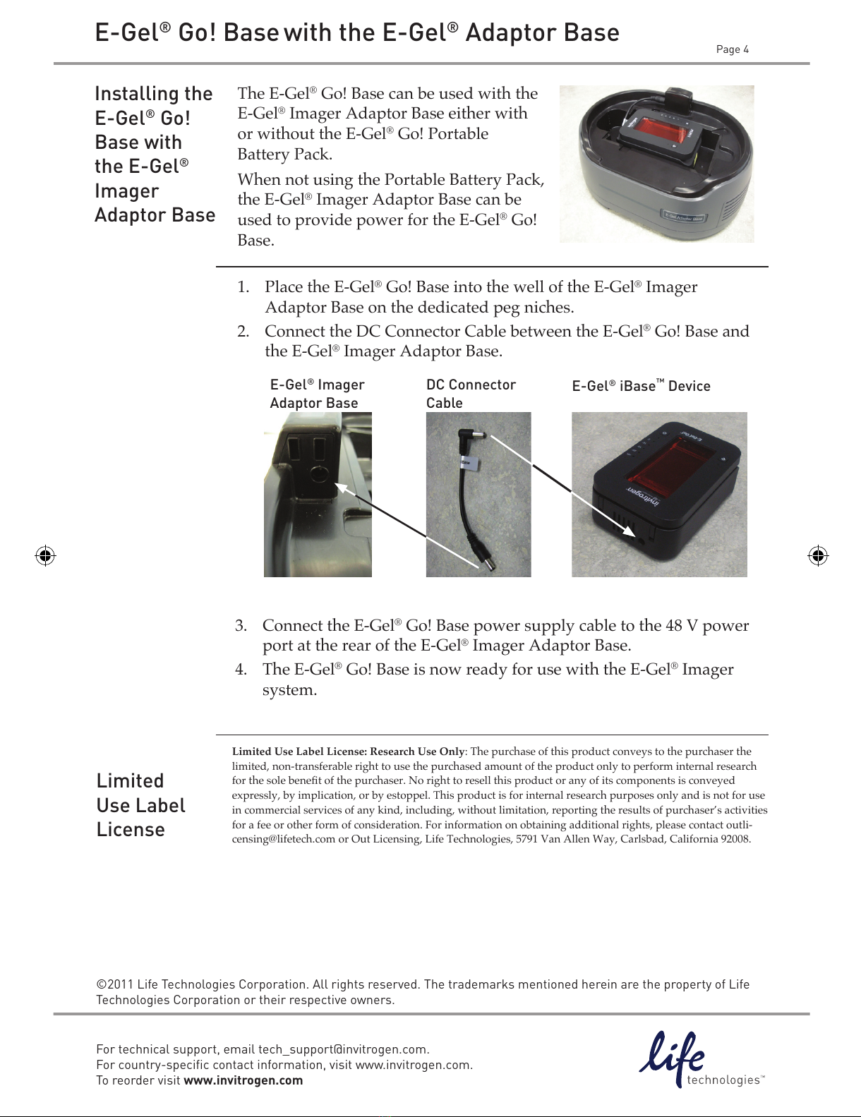
The E-Gel® Go! Base can be used with the
E-Gel® Imager Adaptor Base either with
or without the E-Gel® Go! Portable
Battery Pack.
When not using the Portable Battery Pack,
the E-Gel® Imager Adaptor Base can be
used to provide power for the E-Gel® Go!
Base.
Installing the
E-Gel® Go!
Base with
the E-Gel®
Imager
Adaptor Base
1. Place the E-Gel® Go! Base into the well of the E-Gel® Imager
Adaptor Base on the dedicated peg niches.
2. Connect the DC Connector Cable between the E-Gel® Go! Base and
the E-Gel® Imager Adaptor Base.
3. Connect the E-Gel® Go! Base power supply cable to the 48 V power
port at the rear of the E-Gel® Imager Adaptor Base.
4. The E-Gel® Go! Base is now ready for use with the E-Gel® Imager
system.
DC Connector
Cable
E-Gel® Imager
Adaptor Base
E-Gel® iBase™ Device
E-Gel ImagerBase.indd 4 8/10/2011 4:15:33 PM
All manuals and user guides at all-guides.com
This manual suits for next models
2
Table of contents
Popular Adapter manuals by other brands

Clas Ohlson
Clas Ohlson L133 quick start guide

on networks
on networks Powerline 500 Plus installation guide

Philips
Philips SWV3458W Specifications

D-Link
D-Link WNA-1330 user manual

Allied Telesis
Allied Telesis AT-2916SX Installation and user guide

GROM Audio
GROM Audio GROM-MST4 AUDI MMI 2G Operation manual