Light Sky SUPER SCOPE PRO User manual

SUPER SCOPE PRO
E-mail:
n
Address: No. 43, Yunfeng Road, Xiuquan Street,
Huadu District, Guangzhou, China

-1-
CONTENTS
Congratulations on choosing our company product! We thank you for your custom.
◆ Please keep in mind that this product, like other products of the company, adheres to the concept of
people-oriented design and manufacture, and takes product quality as the foundation.
◆ We put the interests of customers first, and do our best to meet customer requirements.
◆ Please read this instruction manual carefully and keep it for future reference. In the case of fully
understanding the product information, strictly abide by theUse the instruction manual to ensure that
the product is installed, used and serviced correctly and safely.
◆ Our company is not responsible for any damage to lamps or other performance due to personal failure
to follow the instructions during installation, use and maintenance.responsibility.
◆ Our company reserves the right to modify the manual at any time and without prior notice.
1. Safety Instructions....................................................................................................2
2. Technical Specifications ...........................................................................................5
2.1. Attachment And Size ........................................................................................7
3.Color/Gobo/Prism ...........................................................................................9
4. Control Panel ..........................................................................................................10
5. Connection and control ..........................................................................................11
5.1. Power supply connection ...............................................................................11
5.2. DMX 512 Connection......................................................................................12
6. How To Set The Unit ...............................................................................................13
6.1. Main Function.................................................................................................13
6.2. Channel Setting..............................................................................................15
6.3. Address Setting..............................................................................................15
6.4. DMX 512 Configuration ..................................................................................16
7. Electrical Connection Diagram ...............................................................................19
8. Troubleshooting......................................................................................................20
9. Fixture Cleaning......................................................................................................22
10. Duty exonerative and copyright protectio.............................................................22

-2-
The following symbols are used to identify important safety information on the product
and in this manual:
WARNING
1.Safety Instructions
Important:
Damages caused by the disregard of this user manual are not subject to warranty.
The dealer will not accept liability for any resulting defects or problems.
Unpack and check carefully to ensure that there is no transportation damage before
using the unit.
This product is for indoor use only. Use only in a dry location.
Do install and operate by qualified operator.
The light source in this luminaire should be replaced by the manufacturer or its service agent
or a similarly qualified person, always cut off the power supply before replacing he light
source.
Do not allow children to operate the fixture.
Use safety chain when fixing the unit. Handle the unit by carrying its base instead of head
only.
Please read the instruction carefully which includes important information about
the installation, usage and maintenance.
Please keep this User Manual for future consultation. If you sell the unit to another user,
be sure that they also receive this manual.

-3-
The unit must be installed in a location with adequate ventilation, at least 20cm from
adjacent surfaces.
Be sure that no ventilation slots is blocked, otherwise the unit will be overheated.
Before operation, ensure that you are connecting this product to the proper voltage in
accordance with the specifications in this manual or on the product’s specification label.
It’s important to ground the yellow/green conductor to earth in order to avoid electric shock.
Minimum ambient temperature Ta: 0℃. Maximum ambient temperature Ta: 40℃.
Do not operate this product at a lower or higher temperature.
Do not connect the device to any dimmer pack.
When the lamp is running, do not place combustible objects next to it. The shortest
distance between the device and inflammable and explosive objects or materials is 0.5m.
Make sure the power cord is not crimped or damaged; replace it immediately if damaged.
Unit’s surface temperature may reach up to 80℃. do not touch the housing
bare-handedduring its operation.
Avoid any flammable liquids, water or metal from entering the unit. Once it happens,
cut off the mains power immediately.
Do not operate in a dirty or dusty environment. do clean the fixture regularly.
Do not touch any wire during operation as there might be a hazard of electric shock.
Avoid entanglement of the power cord with other wires.
The minimum distance to objects/surface must be more than 3 meters.
In the event of serious operating problem, stop using the unit immediately.
Never turn on and off the unit time after time.
The housing, the lenses, or the ultraviolet filter must be replaced if they are visibly
damaged.
Do not open the housing as there are no user serviceable parts inside.
Do not attempt to operate this unit if it becomes damaged. do not attempt any
repairs yourself. Repairs carried out by unskilled people can lead to damage or
malfunction. Please contact the nearest authorized technical assistance center if needed.
Disconnect this product from its power source before servicing.
Do use the original packaging if the device is to be transported.
Avoid direct eye exposure to the light source while the product is on.

-4-
Do not operate this product if you see damage on the housing, shields, or cables.
Have the damaged parts replaced by an authorized technician at once.
Installation:
The fixture should be fixed on the clamp. Always ensure that the unit is firmly fixed to
avoid vibration and slipping off during operation. Ensure that the trussing or area of
installation must be able to hold 10 times the weight without any deformation. Always
install a safety cable that can hold at least 12 times the weight of the fixture when
installing.do install and operate by qualified operator. It must be installed in a place where
there is out of the reach of people.

-5-
2.Technical Specifications
OPTICAL
- Light source: 450W white LED module
- Zoom range: 4°- 53°
- Optical lens: coated with high anti-reflection coating, diameter 133mm
- Color temperature: 6500K
- Color rendering index: RA≥70 / RA≥90 (cut into high rendering index filter)
- Illuminance: 26000 Lux@10m
- Luminous flux: 21000 Lm
- Light source lifespan: ≥ 20000H
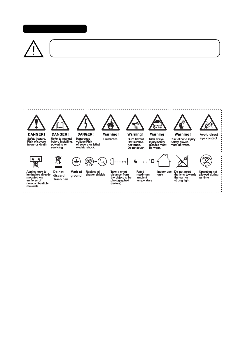
COLOR
- CMY infinite color mixing
- CTO color temperature linear adjustment (3000K-6500K)
- 5 color chips + high-resolution finger + white light, can realize two-way color rainbow, two-color step-by-
step gradient (linear movement), two-way rotation of color wheel, random color mode.
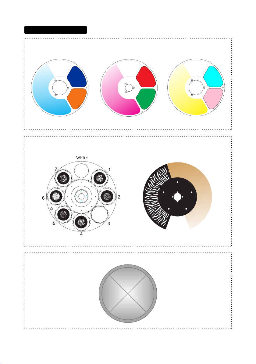
PATTERN
- Rotating gobo wheel:7 kinds of glass patterns + white circle, pluggable and replaceable, can realize
rotation, flowing water,shaking effects, the outer diameter of the gobo is 22.9mm, and the inner diameter of
the gobo is 15mm.
- Effect disc (water texture)+CTO color temperature linear adjustment, which can achieve flowing and
shaking effects.
- Eight-direction cutting: 4 pieces of gratings can achieve fast and smooth cutting, and the eight cutting
directions and angles can be controlled separately, each single piece can achieve complete light closure,
and the entire cutting module can be rotated ±45º.
EFFECT
- Prism: 4 prism, capable of bidirectional rotation.
- Soft light effect: adjustable independent soft light effect.
- With electric aperture, 5-100% linear adjustment, with macro function and multi-effect change.
- Electronic dimming, 0-100% linear dimming, uniform light spot
- Electronic strobe speed is 1-25 times/second
- LED refresh rate: 1000Hz ~ 25KHz
CONTROL
- Control channel: 33CH、36CH
- Protocol: standard DMX512 , RDM , ArtNet
- Data connection: three-core or five-core signal input/output
- Display: LCD liquid crystal screen

-6-
SOFTWARE
- Software upgrade via USB or DMX interface
- Intelligent temperature control to ensure LED life
X, Y AXIS MOVEMENT
- X axis: 540° 8bit/16bit precision scanning
- Y axis: 270° 8bit/16bit precision scanning
POWER AND POWER
- : AC 100-240V ~ 50/60HzInput voltage rangr
- Maximum power:520W
- Power factor: 0.98
SIZE AND WEIGHT
- size: 442mm×262mm×648mm
- N.W: 26.3kg
- Carton packing (default): 495mm×365mm×755mm G.W: 32.1kg (include foldable clamp)
- Flycase Size(2 sets):730×575×845mm G.W:95.3 Kg
OTHER
- Protection class: Ip20
- Working environment: 0℃ ~ 40℃
- Maximum surface temperature of the lamp body: 80°C
- Maximum lamp current: 5.2A/110V; 2.6A/220V
- Optional accessories: FAST LOCK
APPROVALS
- The product implementation standard: GB 7000.1-2015 GB7000. 217-2008
- 、Approved certifications: CE RoHs
- The product complies with the following EU directives:
Low Voltage Directive 2014/35/EU . EMC Directive 2014/30/EU-

-7-
2.1.Attachment And Size
Attachment contents-Fig.1
Size-Fig.2
illuminationdiagram
10 20 30 50
53°
4°
Diameter(m)
Diameter(m)
Distance(m)
0.62 1.24 1.86 3.1
11.38 22.76 34.14 56.9
4° Lux
53° Lux 300 75 30
12
26000 6500 2800 1000
0.93
17.07
130
11500
15
X1 X 1
Certificate of conformity
X1 X1 X 2
power cord
X1
FAST LOCK
(Optional)
x2
X2

-8-

-9-
3.Color/Gobo/Prism
CMY-color wheel
Pattern-Effect disc
Prism
CMY
Green
Red
Orange CRI
Cyan
Blue
1
2
3
1
2
3
1
2
3
white white white
CTO

-10-
OK confirmation key
UP
DOWN
To the left
To the right
2.Button:
1.Display: To show the various menus and the selected function.
4.Control Panel
3.Socket version power input: connect the power supply.
4.Power output: Connect the lamp power output adapter.
5.DMX inputloutput: Used for DMX512 connection, use 3/5 core XLR signal
cable toconnect console and lamps,And input/output DMX signal.
6.Art-net: The information of the lamp can be transmitted to the main
controllerthrough the network cable, and the lamp can be controlled through
RJ45(optional).
7.Firmware upgrade: Used to upgrade the fixture’s firmware.
8.FUSE:10A.
5
46
3
7 8
12

-11-
5.1.Power supply connection
- The bus connecting the power supply must be installed by a qualified professional technician.
- After completing all the above operations and ensuring that it is installed, you can power on the
lamp to operate.
5.Connection and control
POW ER in
out
in POWER EN D
The N terminal is connected
with the blue line.
The ground wire is connected to the
yellow-green wire
The L terminal is connected
with the brown line.
Watertight seal ring

-12-
5.2.DMX 512 Connection
1. At last unit, the DMX cable has to be terminated with a terminator. Solder a 1200hm 1/4W
resistor between pin 2(DMX-) and pin 3(DMX+) into a 3-pin XLR-plug and plug it in the DMX-output
of the last unit.
2. Connect the unit together in a “daisy chain” by XLR plug cable from the output of the unit to
the input of the next unit. The cable cannot be branched or split to a “Y” cable. DMX 512 is a very
high-speed signal. Inadequate or damaged cables, soldered joints or corroded connectors can easily
distort the signal and shut down the system.
3. The DMX output and input connectors are pass-through to maintain the DMX circuit, when one
of the units’ power is disconnected.
4. Each lighting unit needs to have a DMX address to receive the data by the controller. The
address number is between 1-512.
5. The end of the DMX 512 system should be terminated to reduce signal errors.
6. 3 pin XLR connectors are more popular than 5 pins XLR.
3 pin XLR: Pin 1: GND, Pin 2: Negative signal (-), Pin 3: Positive signal (+)
5 pin XLR: Pin 1: GND, Pin 2: Negative signal (-), Pin 3: Positive signal (+), Pin4, Pin5 not used.
DMX - output
1
- Shield
2 - Signal (-)
- Signal (+)
- Not connected
- Not connected
3
4
5
1
2
3
DMX-input
- Shield
- Signal (-)
- Signal (+)
- Not connected
- Not connected
4
5
DMX512 in
in out in SIGNAL END

-13-
Turn on the fixture, press the OK button to enter the menu mode, use the UP/DOWN buttons to find the menu,
when the preset menu is shown on the display, press the OK button to confirm, use the UP/DOWN buttons to
select a submenu, then press the OK button to save Settings, use the left button to return to the previous menu.
The main functions are as follows:
6.How To Set The Unit
6.1.Main Function
Main menu I menu II menu III menu Ⅳ menu
DMX SETTING
→
Address → 1-512
Channel mode → Standard (33)
Extended(36)
Input mode → DMX 512
Artnet
NoDMX State Black
Hold
Info
→
Fixture times →
Power on time 0 - 99999H
LED on time 0 - 99999H
All
time 0
-
99999H
Temperatures LED
TEMP
→ Drive
TEMP
RDM
info → UID:0x3888XXXXXXXX
DMX
live →
1.Pan
→
0
-
255
2.Pan
fine 0
-
255
3.......
0
-
255
Version
info →
Display VX.XXX
Pan/Tilt VX.XXX
LED
module VX.XXX
Gobo
module VX.XXX
Blade
module VX.XXX
Zoom
module VX.XXX
Fan
Info
InFan
Voltage
OutFan
Voltage
InFan1
InFan2
OutFan1
OutFan2
Person
Pan/Tile
Pan
invert OFF
ON
Tilt
invert OFF
ON
Fan
mode →
Hight Brightness
Silent
Super Silent
Display →
Language English
Chinese
Backlight
time Always
Auto
(30S)
Intensity 0
-
100
Rotation
Normal
Rotate
180
Auto
Art-Net
IP
Address xxx.xxx.xxx.xxx
Mask
Address xxx.xxx.xxx.xxx
Net
Address xxx.xxx.xxx.xxx
Sub Net Address xxx.xxx.xxx.xxx
Universe Address xxx
Dimmer Curve →
Linear
Square 1(Default)
Square 2
SCurve
Led Preq Set →
1000 Hz (Default)
3600 Hz
7200 Hz
25000 Hz
GoboFan
FrameFan
HeadFan

-14-
Main menu I menu II menu III menu Ⅳ menu
Manual →
Manual Control →
1.Pan
→
0 - 255
2.Pan fine 0 - 255
3...... 0 - 255
Reset →
Total reset
Pan/Tilt reset
Gobo reset
Color reset
Profile reset
Focus reset
Effect
reset
Test →
Test
all
→
Testing
Test
pan/tilt Testing
Test
effects Testing
Service →
Fixture
state →
Memory
IC
→
OK/Reset/Error
Angle
Sensor OK/Reset/Error
Pan
Encodeer OK/Reset/Error
Tilt
Encoder OK/Reset/Error
Pan OK/Reset/Error
Tilt OK/Reset/Error
Zoom OK/Reset/Error
Focus OK/Reset/Error
Cyan OK/Reset/Error
Magenta OK/Reset/Error
Yellow OK/Reset/Error
RotGobo OK/Reset/Error
GoboRot OK/Reset/Error
Animation OK/Reset/Error
Frame OK/Reset/Error
FrameRot OK/Reset/Error
Iris OK/Reset/Error
Prism OK/Reset/Error
Frost OK/Reset/Error
Adjust →
Pan
→
0
-
255
Tilt 0
-
255
...... 0
-
255
Factory →
Factory
Reset → YES
/
NO
Reset
timers →
Reset
power
on
timers
→
YES/NO
Reset
led
timers YES/NO
Reset
all
timers YES/NO
Update
→
Simple
update →
Display
Pan/Tilt
...
ALL
Whole update
→
Display
Pan/Tilt
...
ALL
Logo select

-15-
6.2.Channel Setting
Enter the MENU menu, select the Personal Settings function, select the channel mode, press the OK
button to confirm, you can use the up and down keys to select:33 channels (default), 36channels,
Press the OK key to enter the selection confirmation and return to the previous menu.
6.3 Address Setting
Enter MENU, select the DMX setting function, select the address code setting, press the OK button to
confirm, the current DMX address will be displayed on the display. Use the up/down buttons to select
addresses 001~512, and press the OK button to save. Press the OK button to return to the previous
menu.
Please refer to the following diagram to address your DMX512 channel for the first 4 units.
Channel mode Unit 1
Address
Unit 2
Address
Unit 3
Address Unit
Address
4
6.3.Address Setting
33 CH
36 CH
1 34 67 100
137 73 109

-16-
6.4.DMX 512 Configuration
Please control the fixture by referring to the configurations below
33 Channel 36 Channel DMX Function Note
1 1 0--255 Pan positioning
2 2 0--255 Fine Pan positioning
3 3 0--255 Tilt positioning
4 4 0--255 Fine Tilt positioning
/ 5 0--255 Speed pan/tilt
5 6
DeviceSet(Hold 3s)
0--9 No function
10--19 Fan high speed
20--29 Fan auto speed
30--39 Fan slow speed
40--49 Reset
Pan&Tilt
50--59 Reset
CMY
60--69 Reset
Gobo
70--79 Reset
Frame
80--89 Reset
Head
90--99 Reset
other(except
P&T)
100--109 Reset
All
110--119 No
function
120--129 No
function
130--139 Pan
invert
on
140--149 Pan
invert
off
150--159 Tilt
invert
on
160--169 Tilt
invert
off
170--177 LED
frequency
1kHz
178--185 LED
frequency
3.6kHz
186--193 LED
frequency
7.2kHz
194--199 LED
frequency
25kHz
200--204 Dimmer
curve
linear
205--209 Dimmer
curve
square
210--214 Dimmer
curve
inv--square
215--219 Dimmer
curve
“S”
220--229 Dimmer fast
230--239 Dimmer
smooth
6 7 0--255 Cyan
7 8 0--255 Magenta
8 9 0--255 Yellow
9 10
Virtual
ColorWheel
0--5
CMY enable
6--23 Red
24--41
Orange
42--59
CRI
60--77
Green
78--95 light blue
96--113
Blue
114--133 CMY enable
134--194 virtual Colorwheel CW slow to fast
195--255 virtual Colorwheel CCW fast to slow
RotgoboWheel
0--9 Open
10--19 RotGobo1
20--29 RotGobo 2
30--39 RotGobo 3
40--49 RotGobo 4
240--255 No function

-17-
33 Channel 36 Channel DMX Function Note
10 11
50--59 RotGobo 5
60--69 RotGobo 6
70--79 RotGobo 7
80--87 RotGobo1shake,slow to fast
88--95 RotGobo2shake,slow to fast
96--103 RotGobo3shake,slow to fast
104--111 RotGobo4shake,slow to fast
112--119 RotGobo5shake,slow to fast
120--127 RotGobo6shake,slow to fast
128--135 RotGobo7shake,slow to fast
136--139 Open
140--194 RotGoboWheel
CW
fast
to
slow
195--249 RotGoboWheel
CCW
slow
to
fast
250--255 Random
Gobo
11 12
GoboRot
0--127 GoboRot
indexing
0°--
360°
128--189 RotGobo
CW
fast
to
slow
190--193 Stop
194--255 RotGobo
CCW
slow
to
fast
12 13 0--255 CTO
0--127 Animation
index
128--255 Animation
rotation
13 14
0--255 BladeA
position1
14 15
0--255 BladeA
position2
15 16
0--255 BladeB
position1
16 17
0--255 BladeB
position2
17 18
0--255 BladeC
position1
18 19
0--255 BladeC
position2
19 20
0--255 BladeD
position1
20 21
0--255 BladeD
position2
21 22
0--255 Frame
Rot
22 23
Framing
Macro
23 24
Iris
0--127 Iris
Indexing
128--159 Slow
close
fast
open
;
slow--fast
160--191 Fast
close
slow
open;
fast
--slow
192--255 Slow close slow open ;slow--fast
24 25
Prism&PrismRot
0--9 Prism out
10--63 Prism In & indexing
64--127 Forwards prism rotation from slow to fast
Effect wheel
0--10 No function
11--20 Square
21 --30 Rectangle
31 --40 Triangle
41 --50 Trapezoid
51 --60 Sector
61 --70 Semi-circle
71 --80 Parallelogram
81 --255 No function

-18-
33 Channel 36 Channel DMX Function Note
/31 0--255 ZoomFine16bit
29 32
Strobe
0--9 Strobe closed
10--19 Strobe open
20--68 Normal strobe effect slow to fast
69--79 Strobe open
80--128 Pulse strobe
129--139 Strobe open
140--188 Random strobe
189--255 Strobe open
30 33 0--255 Dimmer
31
34
0--255 Dimmer
Fine
32 35
Auto
Focus
0--127 Auto
Focus
Disable
128--158 10m
Auto
Focus
Enable
159--190 15m
Auto
Focus
Enable
191--225 20m
Auto
Focus
Enable
226--255 30m
Auto
Focus
Enable
33 36 0--255 Auto
FocusFine
128--191 Backwards
prism
rotation
from
fast
to
slow
192--207 prism flickered 90°
208--223 prism flickered 180°
224--239 prism flickered 270°
240--255 prism flickered 360°
25 26
0--255 Frost
27 28 0--255 Focus8bit
/29 0--255 FocusFine16bit
28 30 0--255 Zoom8bit
26 27

-19-
7.Electrical Connection Diagram
Table of contents