Lilliput OWON VDS6000 Series User manual


Copyright © Lilliput. All rights reserved. Licensed software products are owned by Lilliput or its
subsidiaries or suppliers, and are protected by national copyright laws and international treaty
provisions.
OWON products are covered by CHINA and foreign patents, issued and pending. Information
in this user manual supersedes that in all previously published material. Specifications change
privileges reserved.
OWON is the registered trademark of Lilliput.
Contacting Lilliput
Fujian Lilliput Optoelectronics Technology Co., Ltd.
No. 19, Heming Road
Lantian Industrial Zone, Zhangzhou 363005 P.R. China
For product information, sales, service, and technical support:
In CHINA, call 0592-257-5666.
Worldwide, back to your direct buying source, or send email to info@owon.com.cn , or call
+86-592-257-5666.

Warranty
Thanks for choosing OWON product, in the coming days, really hope you will enjoy the time
that OWON product accompanies you.
OWON product, created and made by Lilliput.
Since the delivery date, OWON product been granted 36 natural months’ warranty for device,
and 12 months’ warranty for attached parts / accessories.
*The delivery date here means the one written onto formal shipping documents given to first-hand buying
party.
Within warranty period of OWON product, provided any non-outside force defects appear,
Lilliput provides 3 options for first-hand buying party -
option 1. to return defective product only;
option 2. to replace the defective product;
option 3. to repair the defective product.
To assure the timely service within warranty period of OWON product, the first-hand buying
party should notify Lilliput of the non-outside force defects in no time, in written form.
Lilliput recommends OWON product users to register your product online via “Support &
Service” column from official English website www.owon.com.cn , so as to get timely
after-sales service.
This warranty shall not apply to any defect, damage caused by improper operation, or
improper / inadequate maintenance towards OWON product. Lilliput shall not be obligated to
under this warranty -
a). repair damages resulted from attempts by personnel other than those from Lilliput, or
authorized one by Lilliput to repair or service OWON product;
b). repair damages resulted from improper operation, or improper connection to incompatible
equipment towards OWON product;
c). service OWON product that has been modified or integrated with other products, provided
the effect of such modification or integration increases the difficulty of servicing non-original
OWON product.
THIS WARRANTY IS GIVEN BY LILLIPUT WITH RESPECT TO OWON PRODUCT IN LIEU
OF ANY OTHER WARRANTIES, EXPRESS OR IMPLIED. LILLIPUT AND ITS VENDORS
DISCLAIM ANY IMPLIED WARRANTIES OF MERCHANTABILITY OR FITNESS FOR A
PARTICULAR PURPOSE. LILLIPUT’S RESPONSIBILITY TO REPAIR OR REPLACE
DEFECTIVE PRODUCTS IS THE SOLE AND EXCLUSIVE REMEDY PROVIDED TO THE
CUSTOMER FOR BREACH OF THIS WARRANTY. LILLIPUT AND ITS VENDORS WILL
NOT BE LIABLE FOR ANY INDIRECT, SPECIAL, INCIDENTAL, OR CONSEQUENTIAL
DAMAGES IRRESPECTIVE OF WHETHER LILLIPUT OR THE VENDOR HAS ADVANCE
NOTICE OF THE POSSIBILITY OF SUCH DAMAGES.

Table of Contents
I. General Safety Requirements...........................................................................................................5
II. Safety Terms and Signs.................................................................................................................... 6
III. PC Configuration Requirements.....................................................................................................9
IV. Communication Interface Introduction.......................................................................................10
V. How to Communicate Device with PC........................................................................................11
i. to install PC Software..............................................................................................................11
ii. to install NI-VISA driver..........................................................................................................11
iii. to run PC Software................................................................................................................ 14
iv. to communicate device with PC.......................................................................................... 15
VI. Operation Interface of PC Software.......................................................................................... 16
VII. Device Operation......................................................................................................................... 19
i. how to set the probe compensation..................................................................................... 19
ii. how to set the vertical system from PC software..............................................................19
iii. how to set the horizontal system from PC software........................................................ 21
iv. how to set the trigger system from PC software.............................................................. 21
v. how to set channel from PC software................................................................................. 24
vi. how to use automatic measurement.................................................................................. 26
vii. how to set sampling mode.................................................................................................. 28
viii. how to set built-in function generator............................................................................... 31
ix. how to use cursor measurement........................................................................................ 31
x. how to set the display system.............................................................................................. 33
xi. how to change utility setting................................................................................................ 35
xii. how to use main action button............................................................................................36
xiii. how to use LAN communication interface....................................................................... 37
xiv. how to work WiFi with PC software.................................................................................. 46
VIII. Technical Specifications............................................................................................................ 53
IX. Appendix.........................................................................................................................................57
Appendix A. Device Accessory List......................................................................................... 57
Appendix B. Device Maintenance............................................................................................58

5
I. General Safety Requirements
! Before using the device, Lilliput strongly recommend to browse “Safety Warnings” carefully and completely, so as to
avoid any possible body injury, or any damages to the device, or its accessories, or communicated facility. !
Safety Warnings
i. The device only been allowed to work within specified application scenario.
ii. Before communicating the device with PC, please refer to user manual to familiarize the allowed rating
value completely.
iii. Making sure the allowed rating value of all terminals been well-followed, so as to avoid any potential
short circuit or electric shock.
iv. NO direct body touch with any naked conductor of device when working the device. Naked conductor
covers joints, connecting probe tip, communication interface, and others.
v. No further operation is allowed provided any undetermined failure appears when working the device,
better to seek the assistance of qualified technicians.
vi. DO NOT work the device in humid environment.
vii. DO NOT work the device in explosive environment.
viii. Keep the device in good ventilation environment, and always keep the device surface clean and dry.
ix. Better to have qualified technicians to do device maintenance.

6
II. Safety Terms and Signs
Safety Terms
Terms in this user manual. It covers,
Warning It states the condition or the operation that may cause body injury or permanent
life loss.
Caution It states the condition or the operation that may cause device damage, or its
accessory damage, or communicated facility damage.
Terms on the device. It covers,
Danger It means the operation may result in the immediate body injury.
Warning It means the operation may result in potential body injury.
Caution It indicates the operation may result in potential damage to the device, or its
accessory, or communicated facility.
Safety Signs
Signs on the device. It covers,
Hazardous Voltage
please refer to user manual for
further details
Protective Earth Terminal
Chassis Ground
Communication Interface Ground

7
To avoid body injury, and to avoid device damage, its accessory or communicated facility damage, before
working the device, Lilliput strongly recommend to read the following safety information.
Warning
To avoid any potential short circuit or electric shock, DO use original local standard, or manufacturer’s
recommended power adapter.
Warning
The channels of the device is non-isolated electrically. When working the device, to avoid short circuit, the
ground of two probes are NOT allowed to connect to 2 different non-isolated DC level.
The illustration of the device’s built-in ground wire connection -
When the device communicated with PC via USB communication interface (with PC powered by AC
power source), the illustration of the ground wire connection -
It is NOT allowed to measure AC power when the device been powered by AC power source through the
adapter, or when the device powered by PC through USB connection cable (via USB communication
interface of PC, with PC powered by AC power source).

8
Warning
When the device input is getting through 42+ Vp-p (30Vrms), or on circuit of 4800+VA, to avoid any
potential short circuit or electric shock -
i. DO use only probes and adapter from original device accessories, or manufacturer’s recommended
ones.
ii. Before working the device, DO check probes and accessories carefully to see whether any mechanical
damages exists, making sure probes and accessories in normal status.
iii. When device in non-working condition, to remove probes and accessories firstly, then put them in
certain places.
iv. When working the device in CAT II environment,
DO NOT get the 40+ V input voltage from earth surface through any non-isolated input;
DO NOT get the 40+ V input voltage of dropout voltage through any non-isolated input
v. DO NOT introduce input voltage larger than rated voltage, especially when probe attenuation set in 1:1,
since the voltage from probe tip will go through to the device itself.
vi. NO NOT contact the exposed part of metal BNC terminal directly by hand or any other body part.
vii. DO NOT insert any metal object into connectors.
- Note -
i). The rated voltage mentioned in point v. is the fixed value of working voltage, matching VACrms / 50 - 60Hz under AC sine
wave application, and VDC under DC sine wave application;
ii). CAT II indicates local level for electrical appliance and portable device.

9
III. PC Configuration Requirements
Minimum System Requirement
CPU:
Pentium® 4/ 2.4 GHz
Internal Memory:
1GB
Effective Hard Disk Space:
1GB
Recommended System Requirement
CPU:
Pentium® Dual-Core/ 2.4 GHz
Internal Memory:
2GB
Effective Hard Disk Space:
2GB
Other Requirement
Operating System:
Windows 10, or Windows 8 / 7
/ Vista / XP (32-bit, or 64-bit)
Communication Interface:
USB 2.0, or USB1.1; LAN
LCD Resolution:
1024 x 768, or above

10
IV. Communication Interface Introduction
Figue IV-1. Communication Interface of the Device
1. power input: for AC-DC adapter
2. USB host: for Wi-Fi extension
3. USB device (type-C): for PC communication
Note: when the device powered by PC through USB connection cable (via USB communication interface of PC, with PC
powered by AC power source), without adapter connection, the input current should reach 1.5A or above
4. LAN: for PC communication within network
5. Built-in Signal (3.3 V/1 kHz) Output: for probe compensation
6. MULTI: for signal output of function generator
7. CH2: for signal input
8. CH1: for signal input

11
V. How to Communicate Device with PC
i. to install PC Software
firstly, to get the software CD from accessories;
secondly, to run .exe file from software CD on target PC;
thirdly, to wait the PC software successfully installed onto target PC
Note: The PC software for OWON product also available from Lilliput official website www.owon.com.cn
ii. to install NI-VISA driver
to run PC software normally, and smoothly, NI-VISA driver is a must.
Note: On condition that NI-VISA driver, or similar VISA driver already been well-installed onto the target
PC, step ii could be skipped.
i). To download the installer via
http://download.ni.com/support/softlib/visa/NI-VISA/16.0/Windows/NIVISA1600full.exe
ii). Based upon installer fully downloaded, to use mouse double-click it, to press "OK" to get access to
the following window,
via "Browse" to choose the preferred folder, to click "Unzip" until full files unzipped.
Press "OK", to start NI-VISA driver installation.
iii). The following window comes,

12
via "Next", to enter into “Select the installation directories” window,
after locating installation path, click "Next",

13
then "Next", following window comes,
untick the box, then "Next",
14
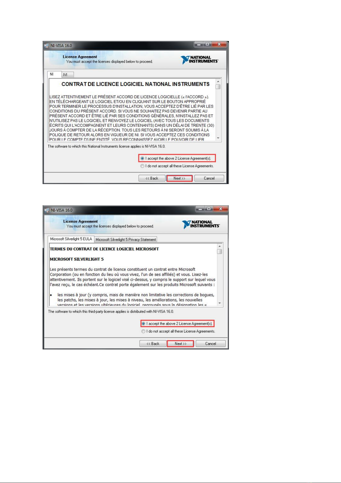
dot-tick "I accept the above 2 License Agreement(s)", again "Next",
dot-tick "I accept the above 2 License Agreement(s)", to continue "Next".
Another "Next", based upon the step done, last "Next", eventually, press "Restart" until PC restarts,
the full NI-VISA driver will be installed successfully.
iii. to run PC Software
Via short-cut to PC software from PC desktop, double-click “VDS6000 Series PC DSO” to start the
software.

15
iv. to communicate device with PC
After powering the device via AC-DC adapter, its status indicator lights red for seconds.
Via USB connection cable (type-C), through matching communication interface, to connect the device
with PC. When the status indicator lights green, PC software detects effective USB port, mouse-click the
detected option to communicate the device with PC.
16
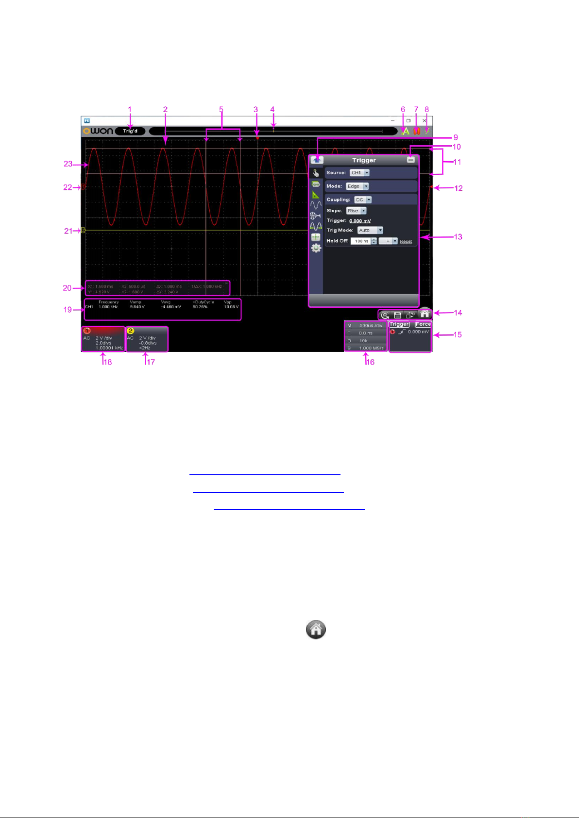
VI. Operation Interface of PC Software
1.
Status Indicating Area: please refer to “Status Details List”
2.
Main Display Area
3.
Red Pointer: to indicate the horizontal position of one conditioned trigger
4.
Violet Pointer: to indicate the trigger position in the recorded data
5.
Time Range measured by certain cursor measurement
6.
Auto Set: please refer to xii. how to use main action button
7.
Run/Stop: please refer to xii. how to use main action button
8.
Single Trigger: please refer to xii. how to use main action button
9.
Back to Home of Function Menu
10.
Hide the current menu
11.
Voltage Range measured by certain cursor measurement
12.
Red Pointer: the trigger level position of Channel 1;
Yellow Pointer: the trigger level of Channel 2.
Via dragging Red / Yellow Pointer upwards or downwards, to adjust the trigger level position of Channel 1 / 2.
13.
Function Menu: to hide/show it via mouse-clicking ; each side-bar icon matches
corresponding function, please refer to Home of Function Menu for details -

17
14.
Shortcut to back to default factory settings, please refer to "Default" ;
Shortcut to export signal data, please refer to "Pause & Export"
Shortcut to switch between 3-window / 1-window VIEW. When working in 3-window VIEW, the
upper-left window is for XY mode.
Shortcut to hide/show Function Menu
15.
Trigger extension window, please refer to iv. how to set the trigger system from PC software
16.
Sample and Period extension window, please refer to
iii. how to set the horizontal system from PC software
17.
Channel extension window for Channel 2, please refer to
ii. how to set the vertical system from PC software
18.
Channel extension window for Channel 1, please refer to
ii. how to set the vertical system from PC software
19.
Measurement Details extension window for Channel 1 and Channel 2, please refer to
vi. how to use automatic measurement
20.
Cursor Measurement extension window, please refer to ix. how to use cursor measurement
21.
Yellow Pointer: to show the grounding base point (zero point) of Channel 2; provided no Yellow
Pointer comes, it means Channel 2 is off.
22.
Red Pointer: to show the grounding base point (zero point) of Channel 1; provided no Red Pointer
comes, it means Channel 1 is off.
23.
The Displayed Area of Input Signal of Channel 1.
Status Details List
i. following status appears when communicating the device and PC
Linking
the device is communicating with PC
Connect
the device successfully communicated with PC
Match
the PC software is matching the device as per model type
Syncing
the PC software is synchronizing the device’s settings
ii. following status reflects the communication between the device and PC
Offline
no communication between PC software and the device
USBFound
the device found
USBDrvErr
USB driver installation error appears
MachineNotSupport
the device not identifiable

18
iii. following status indicates the working of the device
Auto
automatic trigger mode
Ready
ready for receiving trigger
Trig'd
signal triggered
Scan
slow scan mode
Stop
the device stops acquiring signal data
Error
error occurred
ReSyncing
re-synchronize with the device
AutoSet
in process of auto setting
Keyboard Shortcuts
F5
Run/Stop
Ctrl + Enter
Auto Set
Q
1 division less from Channel 1’s voltage division
A
1 division more from Channel 1’s voltage division
W
1 division less from Channel 2’s voltage division
S
1 division more from Channel 2’s voltage division
←
1 division less from time base
→
1 division more from time base

19
VII. Device Operation
i. how to set the probe compensation
Before working the probe with either of input channels (Channel 1 / Channel 2), better to adjust its
compensation, so as to assure ideal measurement effect. Following operation steps to adjust probe
compensation -
i) From PC software operation interface, mouse-click to get access to device function menu,
choose "Channel";
ii) then "CH1", set the "Probe Rate" at certain option (either x1, or x10, or x100, or x1000). Next, from
physical probe, switch the probe attenuation to the matching option correspondingly.
Note: The probe compensation setting from function menu will keep valid until new setting change introduces.
Caution:
The default probe compensation setting into PC software reads x10, before
working the probe with the device, making sure the probe compensation of both
places is matching.
Figure VII- 1. Probe Attenuation Switch Position
Caution:
For physical probe, when the compensation set in x1, the probe itself will
limit the device bandwidth at 5MHz.
To reach the full bandwidth, the physical probe’s compensation should be
set in x10, or above.
ii. how to set the vertical system from PC software
In “Channel extension window for Channel 1 / 2” (as item 18 and 17 described under
VII. Operation Interface of PC Software), related options of vertical system could be adjusted accordingly.
Through voltage divisions,

20
choose the ideal option.
Or through rotating the mouse wheel, to choose the ideal option.
Through zero point position control bar,
to reset zero point position will change the vertical position of the signal, via moving the slider upwards, or
downwards - the farther slider from the center of control bar, the faster the vertical position changes.
Another solution is to drag the zero point pointer upwards or downwards (as item 22 and 21 goes under
VII. Operation Interface of PC Software).
Keyboard Shortcuts
Q
1 division less from Channel 1’s voltage division
A
1 division more from Channel 1’s voltage division
W
1 division less from Channel 2’s voltage division
S
1 division more from Channel 2’s voltage division
This manual suits for next models
4
Table of contents
Other Lilliput Test Equipment manuals


