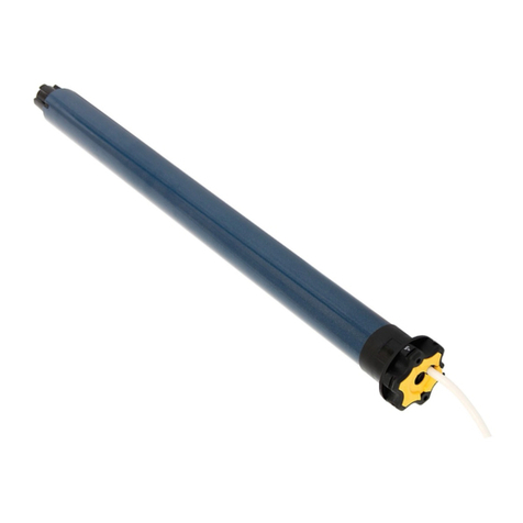
Lin Engineering BLDC50 User manual

BLDC50/100
BRUSHLESS DC MOTOR DRIVE
USER MANUAL
Lin Engineering
BLDC 50/100 Driver Manual
Version 1.0
01/29/2020

BLDC50/100 User Manual
Contents
1 Introduction.................................................................................. 3
1.1 Features.............................................................................................3
1.2 Order Information...............................................................................4
1.2.1 Numbering System.................................................................................4
1.2.2 Compatible Motors..................................................................................4
1.2.3 Brushless DC Motor Cable.....................................................................4
1.3 Block diagram ....................................................................................5
2 Mounting the Drive ...................................................................... 6
3 Connections................................................................................. 6
3.1 Connecting the Power(CN1)..............................................................7
3.2 Connecting the Motor(CN2 and CN3)................................................7
3.3 Connecting the BLDC50/100 Communications........................................8
3.3.1 Connecting to a PC using RS-232(CN5)................................................8
3.3.2 Connecting to a PC using RS-485(CN5)................................................8
3.4 IO Control and Function Description................................................11
3.5 Connecting the Inputs and Outputs(CN4)........................................15
3.5.1 Input Connection ..................................................................................15
3.5.2 Dip Switches ........................................................................................19
3.5.3 Output Connection ...............................................................................20
3.6 Two Potentiometers(RS-232 Only) ...................................................21
3.6.1 Speed Setting.......................................................................................21
3.6.2 Acceleration Setting..............................................................................21
3.7 Status LED Codes ...........................................................................21
4 Operation................................................................................... 22
4.1 Basic operation ................................................................................22
4.2 Setting the acceleration and deceleration .......................................23
5 Motor ......................................................................................... 24
NEMA 17 BLDC MOTOR........................................................................24
NEMA 23 BLDC MOTOR ......................................................................25
6 Setup for EMC ............................................................................ 27
7 Specification ............................................................................... 28
8Contacting Lin............................................................................. 29
NEMA 34 BLDC MOTOR ......................................................................26
Lin Engineering
BLDC 50/100 Driver Manual
Page 2
Version 1.0
01/29/2020

BLDC50/100 User Manual
1 Introduction
Thank you for selecting the Lin Engineering BLDC50/100 Brushless DC Motor Drive. The
BLDC50/100 series DC input drives are based on advanced digital current and velocity control
technology and provide high torque, stable velocity and low noise. We hope our dedication to
performance, quality and economy will make your motion control project successful.
1.1 Features
▪ The structure is compact and the parameter is configurable.
▪12-48VDC supply voltage.
▪Work in velocity mode.
▪Accept analog control signal, digital control signal, RS-232/485 communication command or
MMI control.
▪High response of the PID velocity loop and D/Q current loop control.
▪Brushless sinusoidal current control. With motor phase compensation.
▪The drive can supply 5/10A (rms) maximum continuously current for each motor phase. And
the twice over load 10/20A is allowed for 5 seconds.
▪ With eight single-ended optically isolated inputs (5-24V) which is configurable for sinking or
sourcing by two swtiches, one analog input(0-5V, can be configured by software)and two dar-
lington optically isolated outputs( maxium output current is 80mA).
▪ Outputs can be configured by 8 functions depending on different requirements.
Lin Engineering
BLDC 50/100 Driver Manual
Page 3
Version 1.0
01/29/2020

BLDC100
BLDC50/100 User Manual
1.2 Order Information
1.2.1 Numbering System
Current
5:5 A
Series
BLDCSeries
BL17E19
Motor Type:
BL17E19
BL17E28
BL17E40
BL23E22
BL23E33
BL23E48
BL34E21
BL34E27
BL34E34
0: RS-232
1: RS-485
01: 24V
02: 48V
1.2.2 Compatible Motors
TYPE Model TYPE Model
Single
Shaft
BL17E19-01-RO
Dual
Shaft
BL17E19-01D-RO
BL17E19-02-RO BL17E19-02D-RO
BL17E28-01-RO BL17E28-01D-RO
BL17E28-02-RO BL17E28-02D-RO
BL17E40-01-RO BL17E40-01D-RO
BL17E40-02-RO BL17E40-02D-RO
BL23E22-01-RO BL23E22-01D-RO
BL23E22-02-RO BL23E22-02D-RO
BL23E33-01-RO BL23E33-01D-RO
BL23E33-02-RO BL23E33-02D-RO
BL23E48-02-RO BL23E48-02D-RO
1.2.3 Brushless DC Motor Cable
P/N Length (L)
BLDC Extension - 1m 1m
BLDC Extension - 3m 3m
L±20
Connector(Molex)
Connector(Molex) Connector(Molex)
Connector(Molex)
300±20
Connector: (JST)
Housing: PUDP-18V-S
Crimp: SPUD-001T P0.5
10±2
I/O Cable: P/N 1201-030
01
BL34E21-01-RO BL34E21-01D-RO
BL34E21-02-RO BL34E21-02D-RO
BL34E27-02-RO BL34E27-02D-RO
BL34E34-01-RO BL34E34-01D-RO
10:10 A
Communication
Lin Engineering
BLDC 50/100 Driver Manual
Page 4
Version 1.0
01/29/2020

BLDC50/100 User Manual
1.3 Block diagram
DC Input
Power
Supply
12-48VDC
Internal
Logic
Supply
Optical
Isolation
Y1+
Y1-
Y2+
Y2-
Control
Signal
Optical
Isolation
INCOM
X1/CW/CCW
X2/STDM
X3/EN/RE
X4/SPST
X5/STP
X6/M0
X7/M1
ANALOG
AL
Optical
Isolation
Software
Filter
Status
LED
SPD Address
ACC
DEC
RS-232
RS-485
IGBT
PWM
Power
Amplifier
DSP
MOTOR
HALL
RS-232/RS-485 PC
Setting Display & Key
Status
Status
BLDC50/100
X8/M2
AH
MMI
Setting Display & Key
MMI
MENU ENT
Lin Engineering
BLDC 50/100 Driver Manual
Page 5
Version 1.0
01/29/2020

BLD5/10 User Manual
BLDC50/100 User Manual
2 Mounting the Drive
The BLDCdrive can be mounted only on the narrow side of the chassis. M4 screws should be
used in the two holes at the back of the drive. The amplifiers in the drive generate heat. To
operate the drive continuously at maximum power forced air cooling, as from a fan, should be
provided. Never use the drive in a space where there is no air fl ow or where other devices can
cause the surrounding air to be more than 40 °C. Never put the drive where it can get wet or
where metal particles can fall into it.
3 Connections
To use the BLDC50/100 Drive, the following items are needed:
•DC input of 12 to 48VDC
•Direction, Stop Mode(STMD), Enable, Speed Setting, Stop, Analog or multi-speed setting
•A compatible Brushless Motor
65
Uint:mm
100
30
92
20
CN5
CN4
CN3
CN2
CN1 CN1
CN2
CN3
CN4
CN5
Speed Setting
Connector to RS-232
I/O Connector
Motor Connector
LED LED
Acceleration Setting
RX
VCC
TX
DGND
W
V
U
V-
V+
HALL Connector
Earth Ground
BLDC50/100 BLDC51/101
Power Connector
Earth Ground
Connector to RS485
I/O Connector
Motor Connector
RS-485 Addresses
RX+
RX-
TX+
TX-
GND
W
V
U
V-
V+
HALL Connector
Power Connector
Lin Engineering
BLDC 50/100 Driver Manual
Page 6
Version 1.0
01/29/2020

perfor-mance between 12 and 48 Volts DC. Choosing the
voltage depends on the performance requirement and the
Motor/Drive heat-ing that is acceptable and/or does not cause a
motor/drive over temperature. Higher Voltages will cause the
Motor/Drive to operate at higher temperatures. Using power
supplies with Voltage outputs that are near the drive maximum
voltage may reduce the operational Duty-cycle significantly.
When choosing a Power Supply that is Regulated and is near the V- V+
Drive Maximum Voltage of 48 Volts, a Voltage Clamp may be
required to prevent over voltage when regeneration occurs. The BLDC50/10 0 Drive
R88A-RR08050S used for the Servo/Step Amplifier er will also work
BLDC50/100 User Manual
3.1 Connecting the Power(CN1)
Connecting the DC supply to power connector (CN1) according
to the diagram on the right. Use 16 AWG wire for V+ and V-.
Use 16 AWG for Earth Ground (G).
Care should always be taken when working with voltages.
The BLDC50/100 contains an internal 15A fast acting fuse.
The BLDC50/100 series drives are designed to give optimum
with the BLDC50/100 drive. The R88A-RR08050S can be purchased from Digi-Key
If you choose an unregulated power supply, make sure the no load voltage of the supply
does not exceed the drive’s maximum input voltage specifi cation.
3.2 Connecting the Motor(CN2 and CN3)
Motor connections should be made according to the following diagrams.
V-V+
Vin
-
+
Vout
+
-
Power Supply
Vout
CN1
CN2
CN3
CN4
CN5
BLD5/10-R
Earth Ground
LED
Connector to RS485
I/O Connector
Motor Connector
RS485 Addresses
RX+
RX-
TX+
TX-
GND
W
V
U
V-
V+
HALL Connector
CONNECTOR: MOLEX 43025-0600
CONTACTS: MOLEX 43030-0001
CONNECTOR: MOLEX 39-01-4030
CONTACTS(3X): MOLEX 39-00-0207
Power Connector
Lin Engineering
BLDC 50/100 Driver Manual
Page 7
Version 1.0
01/29/2020
R88A-RR08050S

BLD5/10 User Manual BLDC50/100 User Manual
3.3 Connecting the BLDC50/100 Communications
The BLDC50/100 is available with two types of serial communications, RS-232 (BLDC50/100) or
RS-485 (BLDC51/101). Each type requires a different hardware connection for interface to a PC
or other Host system. The RS-232 version comes with a cable that will provide the interface to an
RS-232 port through a DB9 style connector. The RS-485 version requires the user to provide
both the cabling and the RS-485 interface. Below are descriptions of how to interface both of
these se-rial communication types to a PC.
3.3.1 Connecting to a PC using RS-232(CN5)
Locate the BLDC50/100 within 1.5 meters of the PC. Plug the DB9 connector of the
communication cable that came with the drive into the serial port of the PC. Plug the small end
into the PC/MMI jack on the BLDC50/100. Secure the cable to the PC with the screws on the
DB9 connector.
Its baud rate is 9600bps which cannot be changed now.
Note: If the PC does not have an RS-232 serial port, a USB Serial Converter will be needed.
You can contact Lin Engineering to buy a USB to RS-232 converter.
The RS-232 circuitry does not have any extra electrical “hardening” and care should be taken
when connecting to the RS-232 port as hot plugging could result in circuit failure. If this is a con-
cern the RS-485 version should be used.
3.3.2 Connecting to a PC using RS-485(CN5)
RS-422/485 communication allows connection of more than one drive to a single host PC, PLC,
HMI or other computer. Its baud rate is 9600bps which cannot be changed now. It also allows the
communication cable to be long (more than 300 meters or 1000 feet). The use of Category 5 cable
is recommended as it is widely used for computer networks, inexpensive, easily obtained and cer-
tified for quality and data integrity.
The BLDC50/100 can be used with either Two-Wire or Four-Wire RS-422/485 implementation.
The connection can be point-to-point (i.e. one drive and one host) or a multi-drop network (one
host and up to 16 drives).
NOTE: To use the BLDC50/100 RS-422/485 version with the BLD Configurator software, it
must be connected in the Four-Wire configuration (see below)
RX
VCC
TX
DGND
to PC TX
no Connection
to PC RX
to PC GND
CN5
RX+
RX-
TX+
TX-
GND
CN5
to PC TX+
to PC TX-
to PC RX+
to PC RX-
to PC GND
Lin Engineering
BLDC 50/100 Driver Manual
Page 8
Version 1.0
01/29/2020

BLDC50/100 User Manual
Four-Wire Conguration
Four-Wire Systems utilize separate transmit and receive wires. One pair of wires must connect the
host’s transmit signals to each drive’s RX+ and RX- terminals. The other pair connects the drive’s
TX+ and TX- terminals to the host’s receive signals. A logic ground terminal is provided on each
drive and can be used to keep all drives at the same ground potential. This terminal connects
internally to the DC power supply return (V-), so if all the drives on the RS-422/485 network are
powered from the same supply it is not necessary to connect the logic grounds. One drive’s GND
terminal should still be connected to the host computer ground.
Because the host in a four-wire system never needs to disable its transmitter, software is simpli-
ed. Some converters make this process very difcult to implement and can delay communica-
tions.
NOTE: If the PC does not have an RS-485 serial port, a converter is required. You can
contact Lin Engineering to buy a USB to RS-485 converter.
Two-Wire Configuration
In a 2-wire system, the host must disable its transmitter before it can receive data. This must be
done quickly before a drive begins to answer a query. It is not make the transmit delay in a four
wire system.
to PC GND
to PC TX-
to PC TX+
to PC RX+
to PC RX-
Drive #1
GND
RX-
TX+
TX-
RX+
GND
RX-
TX+
TX-
RX+
GND
RX-
TX+
TX-
RX+
Drive #2 Drive #3
SW4 ON for 120Ω terminating resistor
*
*120Ω
to PC GND
to PC TX+ (B)
to PC TX- (A)
Drive #1
RX+
TX+
TX-
TX+
TX-
TX+
TX-
RX-
GND
Drive #2
RX+
RX- RX-
GND
Drive #3
RX+
GND
SW4 ON for 120Ω terminating resistor
*
*120Ω
Lin Engineering
BLDC 50/100 Driver Manual
Page 9
Version 1.0
01/29/2020

BLD5/10 User Manual BLDC50/100 User Manual
Assigning Addresses
Before the entire system is wired, each drive will need to connect individually to the host computer
so that it can be assigned a unique address.
Once the drive has been connected to the PC as described above, launch the BLD Configurator
software. Apply power to the drive. If a drive has already been congured, click the Upload button
so that the BLD Congurator settings match those of the drive. Click on the Motion button and se-
lect the SCL operating mode. The numerals 0..9 or the special characters : ; < = > ? may be used
as addresses. Make sure each drive on the network has a unique address. Once the address has
been assigned, click Download to save the settings to the drive.
Address SCL Character Address SCL Character
0088
1199
2 2 A :
3 3 B ;
4 4 C <
5 5 D =
6 6 E >
7 7 F ?
Lin Engineering
BLDC 50/100 Driver Manual
Page 10
Version 1.0
01/29/2020

BLDC50/100 User Manual
3.4 IO Control and Function Description
1 +5V USER 2 GND
3 X1 4 Y1+
5 X2 6 Y1-
7 X3 8 Y2+
9 X4 10 Y2-
11 X5 12 AH
13 X6 14 Analog In
15 X7 16 AL
17 X8 18 INCOM
PIN
NUM
SIGNAL
TYPE
SIGNAL NAME FUNCTION
BASIC GENERAL BASIC
1
POWER
SUPPLY
+5V USER The drive provides users with up to 100mA
+5V supply
2 GND External control signal GND
18 INCOM
External opto-coupler power input (common
anode or common cathode connection can
dial to select)
3
INPUT
CW/CCW X1 Clockwise/Counter Clockwise Select
5STMD
(STOP MODE) X2 Stop mode choice input
7EN/RE
(Enable/Reset) X3 Motor enable/disable. It can be used for
alarm reset as well.
9SPST
(SPEED-SET) X4 Internal/external speed-set choice
11 STOP X5 The electromagnetic brake operation is
selected when the motor is stopped.
13 M0 X6 For multi-speed operation, the M0, M1, M2
signals are used in combination.
15 M1 X7
17 M2 X8
12 ANALOG
INPUT
Analog VCC - Using external speed potentiometer setting
speed
14 Analog In -
16 Analog GND -
Lin Engineering
BLDC 50/100 Driver Manual
Page 11
Version 1.0
01/29/2020

BLD5/10 User Manual BLDC50/100 User Manual
4
OUTPUT
Fault+ Y1+ Fault output
6 Fault- Y1-
8 Speed Out+ Y2+
6 pulses are output per each rotation of the
motor output shaft. It can be changed by
BLD congurator.
10 Speed Out- Y2-
- MOVE - This signal is output during motor rotation.
-VA - Output a signal as speed achieved
- Fault2 -
This signal is output when the overload
warning level is exceed when the overload
warning function is set to enable. In
addition, also outputs if an overload alarm is
generated even when the overload warning
function is set to disable (normally closed).
- Warning -
This signal is output if a warning is gener-
ated (overload warning function is acti-
vated)While, it turns OFF if the warning is
released.
- TLC - This signal is output when the motor output-
torque reaches the torque limiting value.
- IDLE - Conguring as general output
*1 Expand output functions are set through software conguration.
*2 the control module may be used to assign the required signals out of the eight input terminals
(X1 to X8) and the two output signal terminals (Y0 and Y1).
Y1-Y2 can be allocated as: Fault/Speed Out/MOVE/VA/Fault2/Warning/TLC/IDLE. (8 in total)
Input Signals Description
The signal state represents the “ON: Carrying current” or “OFF: Not carrying current” state of the
internal photocoupler rather than the voltage level of the signal.
CW/CCW
Switching the CW input will cause the motor to turn clockwise as viewed from the motor shaft,
while switching to the CCW input will cause the motor to turn counterclockwise. The starting
acceleration is set by the acceleration potentiometer (ACC/DEC) or command.
STMD (STOP MODE)
When STOP-MODE is OFF, the motor will stop according to the deceleration set by the acc/dec
potentiometer. When STOP-MODE is ON, it will stop the motor using electromagnetic brake op-
eration.
EN/RE (Enable/Reset)
When ENABLE is ON, the motor will be energized .When ENABLE is OFF, the motor will be
deenergized. Regardless any other input states, ENABLE being OFF has the highest priority, so
that it can be used as emergency stop. By disabling and enabling the drive, it can be reset.
Lin Engineering
BLDC 50/100 Driver Manual
Page 12
Version 1.0
01/29/2020

BLDC50/100 User Manual
SPST(Speed-set)
OFF Internal speed setting
ON External analog signal setting
Multi-speed operation (M0,M1,M2)
8 kinds of speed is available with M0, M1, M2 input. (Speed control mode and position control
mode share the same function)
Default
operating data
Operating speed selection Speed setting
method
M0 M1 M2
0rpm OFF OFF OFF Internal speed
setting
500rpm ON OFF OFF Digital setting
1000rpm OFF ON OFF Digital setting
2000rpm ON ON OFF Digital setting
3000rpm OFF OFF ON Digital setting
3500rpm ON OFF ON Digital setting
4000rpm OFF ON ON Digital setting
4500rpm ON ON ON Digital setting
STOP
When STOP is on, the motor stops in the mode set by STMD.
Output Signal Description
FAULT
FAULT output an error signal when the drive is over-heat, over-current, over-voltage, under-volt-
age or internal voltage bad. The output voltage of error signal can be dened by SCL command
AO.
SPEED OUT
The motor output shaft output
6*(pole pairs) per revolution(default). And the pulse number can be set through the software.
MOVE
This signal is output during motor rotation.
VA
Speed reached command. If the difference between the actual motor speed and the input speed
reaches specied range, the drive will output this signal. The difference range can be dened in
0~+/-400rpm (the default range is +/-200rpm).
FAULT2
In order to avoid overload, the drvie can set the overload level, and use it as overload alarm sig-
nal. With this signal, user can distinguish the real cause of fault or warning.
Lin Engineering
BLDC 50/100 Driver Manual
Page 13
Version 1.0
01/29/2020

BLD5/10 User Manual BLDC50/100 User Manual
Warning
When communication error occurs or back EMF voltage is over range, a warning will happen till
the error is eliminated.
TLC
When the output torque reaches the rated limi, the output is ON.
IDLE
IDLE can be congured as a general output when idle.
Lin Engineering
BLDC 50/100 Driver Manual
Page 14
Version 1.0
01/29/2020

BLDC50/100 User Manual
3.5 Connecting the Inputs and Outputs(CN4)
The connector is an 18-Pin board-to wire connector with secure locking device and designed to
2.0 mm pitch, crimping style and double-row. The pin-out is as follows:
3.5.1 Input Connection
M2
M1
M0
STP
SPST
EN/RE
STMD
CW/CCW
5V
17
15
13
11
9
7
5
3
1
18
16
14
12
10
8
6
4
2
INCOM
AGND
AIN
5V
SPO-
SPO+
FLT-
FLT+
GND
CN4 CONTACTS: JST SPUD-001T-P0.5
HOUSING : JST PUDP-18V-S
Connect to CN4
INCOM
COMMON CATHODE
COMMON ANODE
CW/CCW
STMD
EN/RE
SPST
STP
M0
M1
M2 AGND
AIN
+5V
FLT-
FLT+
SP0-
SP0+
18
0 V
0 V
8
SW1 OFF 5V
10
4
6
12
14
16
3
5
7
9
11
13
15
17
Signal
Conditioning
3K
inside drive
Connecting to control IO with external Sinking Outputs
5-24V
Lin Engineering
BLDC 50/100 Driver Manual
Page 15
Version 1.0
01/29/2020

BLD5/10 User Manual BLDC50/100 User Manual
INCOM
COMMON CATHODE
inside drive
COMMON ANODE
CW/CCW
STMD
EN/RE
SPST
STP
M0
M1
M2 AGND
AIN
+5V
FLT-
FLT+
SP0-
SP0+
18
8
10
4
6
12
14
16
3
5
7
9
11
13
15
17
Signal
Conditioning
SW1 OFF
0 V
5-24V
5V
3k
Connecting to control IO with external Sourcing Outputs
>1.6mA
Lin Engineering
BLDC 50/100 Driver Manual
Page 16
Version 1.0
01/29/2020

BLDC50/100 User Manual
INCOM
COMMON CATHODE
COMMON ANODE
CW/CCW
STMD
EN/RE
SPST
STP
M0
M1
M2
GND
AGND
AIN
+5V
FLT-
FLT+
SP0-
SP0+
18
8
10
4
6
12
14
16
3
5
7
9
11
13
15
17
2
Signal
Conditioning
3K
inside drive
SW1 ON SW2 OFF 5V
0 V
Connecting to control IO with internal Sinking Outputs
Lin Engineering
BLDC 50/100 Driver Manual
Page 17
Version 1.0
01/29/2020

BLD5/10 User Manual BLDC50/100 User Manual
INCOM
COMMON CATHODE
COMMON ANODE
CW/CCW
STMD
EN/RE
SPST
STP
M0
M1
M2 AGND
AIN
+5V
FLT-
FLT+
SP0-
SP0+
18
8
10
4
6
12
14
16
3
Switch or relay
5
7
9
11
13
15
17
Signal
Conditioning
3K
inside drive
SW1 ON
SW2 ON
Connecting to control IO with internal Sourcing Outputs
5V
Lin Engineering
BLDC 50/100 Driver Manual
Page 18
Version 1.0
01/29/2020

BLDC50/100 User Manual
3.5.2 Dip Switches
At the right side of BLD drive there are four switches. If users don’t
want use external power for the IO control, they can switch SW1
“ON” to choose the internal 5V power supply to IO control and “OFF”
means external power supply. When SW1 is “ON”, user should chose
common anode or common cathode control by SW2. SW2 is “ON”
that means user chose common anode IO control. SW2 is “OFF” that
means user chose common cathode IO control.
For RS485 version, SW4 is “ON” that means there is a 120 ohm termination resistor across the
TX+ and TX- terminals. SW3 is reserved.
SW1
SW2
SW3
SW4
BLD
OFF OFF OFF OFF
The four switches on the right side of the BLD drive can be adjusted using a device that is
capable of fitting between the right side grating. Removing the outside layer is also possible but
not recommended due to sensitive nature of the drive electronics.
Lin Engineering
BLDC 50/100 Driver Manual
Page 19
Version 1.0
01/29/2020

BLDC50/100 User Manual
3.5.3 Output Connection
5 – 24 volt
Power Supply
+
-
Connecting a Sourcing Output
PLC
5 – 24 volt
Power Supply
+
-
Driving a Relay
1N4935 suppression diode
relay
BLD
BLD
OUT+
OUT+
OUT-
OUT- IN
COM
5 – 24 volt
Power Supply
BLD
Connecting a Sourcing Output again
PLC
OUT+
OUT-IN
COM
-+
5 – 24 volt
Power Supply
Load
BLD
+
-
Connecting a Sinking Output
OUT+
OUT-
Lin Engineering
BLDC 50/100 Driver Manual
Page 20
Version 1.0
01/29/2020
This manual suits for next models
1
Table of contents
Popular DC Drive manuals by other brands
Allen-Bradley
Allen-Bradley PowerFlex 700H Programming manual
Delta
Delta IED-S Series user manual
BENSHAW
BENSHAW RSi H2 Series instruction manual
Danfoss
Danfoss VLT OneGearDrive operating instructions

GFA
GFA ELEKTROMAT SI 100.30 FU-55,00 10003917 10011 installation instructions
SOMFY
SOMFY J4 WT Full Installation Guide

