Rowan Elettronica 380S User manual

INSTRUCTION MANUAL
Cod.380S.B
BIDIRECTIONAL DRIVE
FOR ROWAN SSERIES HIGH SLIP
THREE PHASE MOTORS
REV. 2 - Data 18/03/11 Data Controllato/Approvato
EMC
CONFORMITY
Motori, azionamenti, accessori e servizi per l'automazione

ROWAN ELETTRONICA SRL page 2 out of 24
INDEX
Boarddescription:
Technical characteristics - Dimensions............................................................................................page. 3
Operating principal .............................................................................................................................page. 4
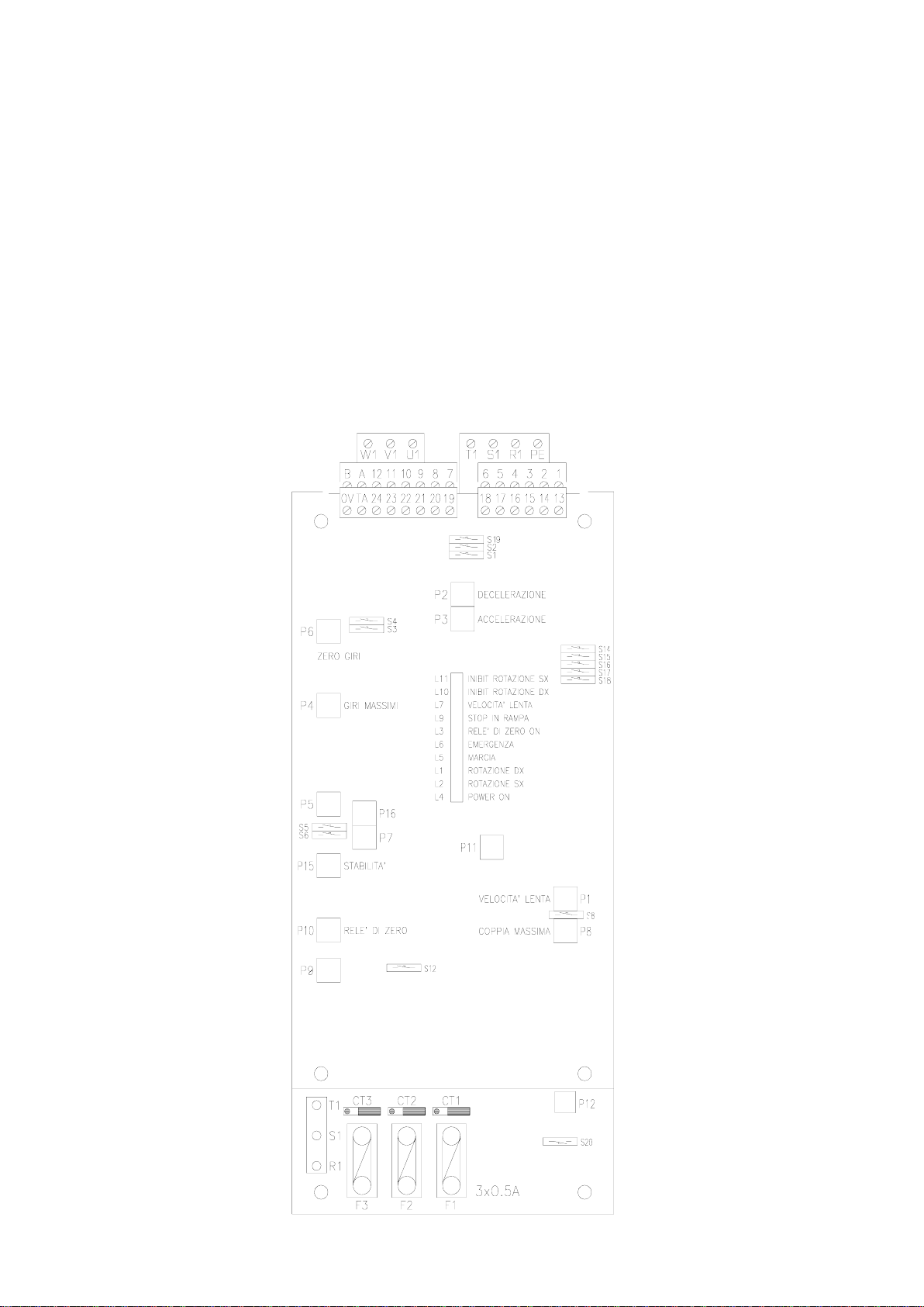
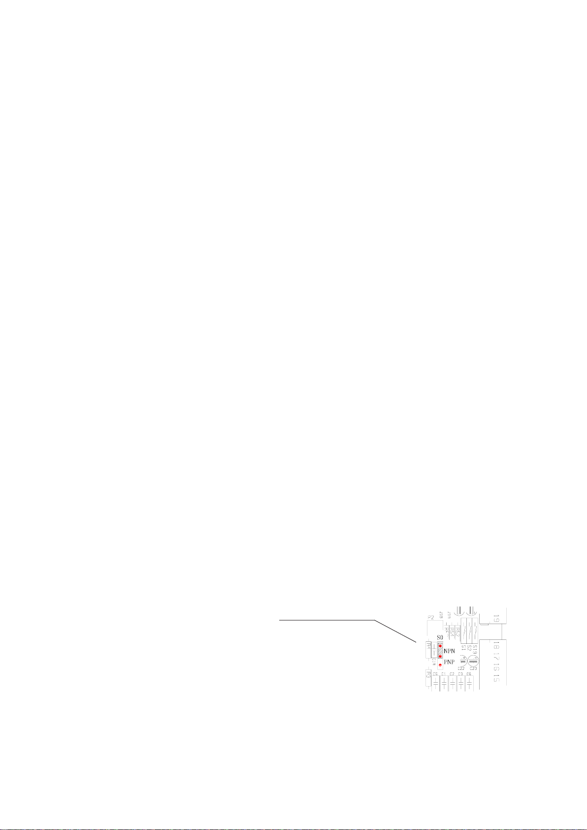
Led,trimmer, dip-switchpositions.................................. .....................................................................page. 4
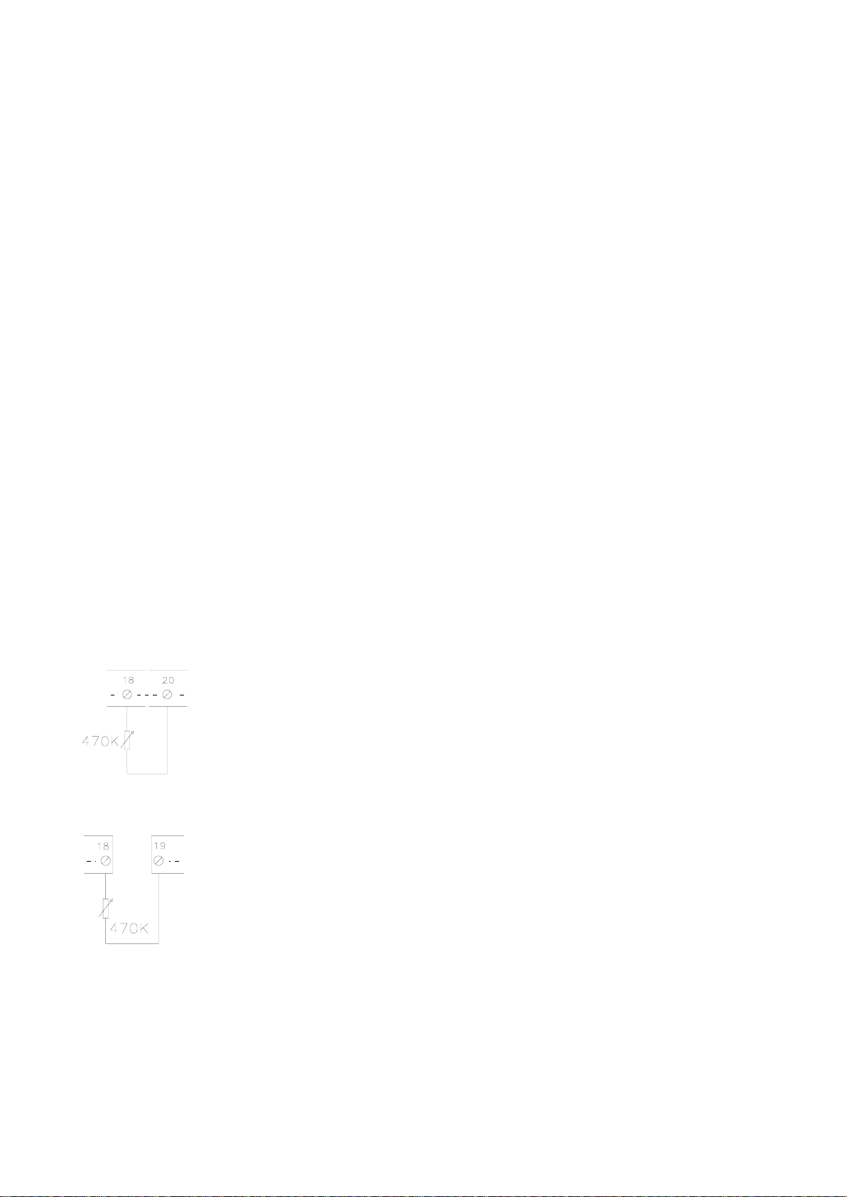
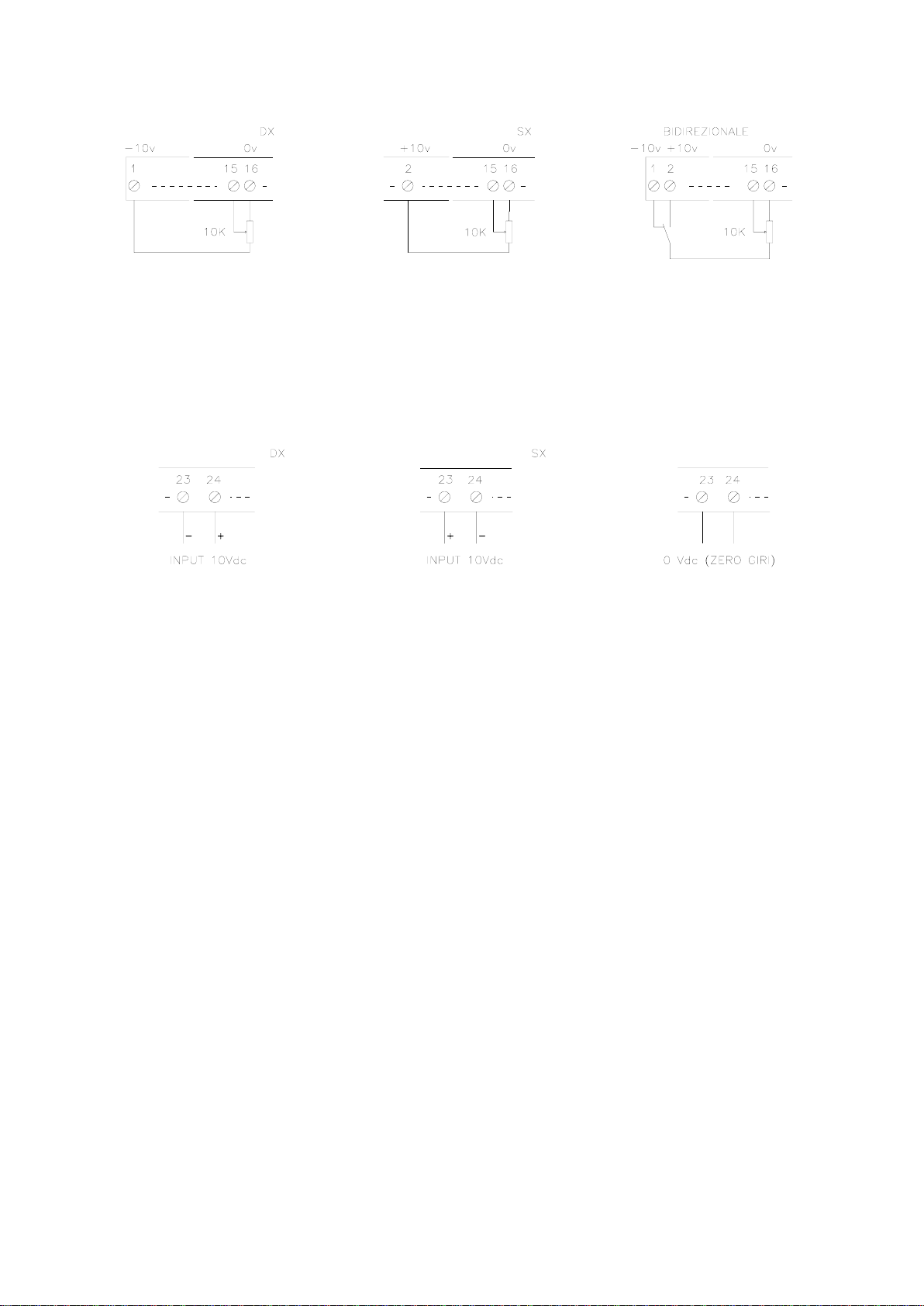
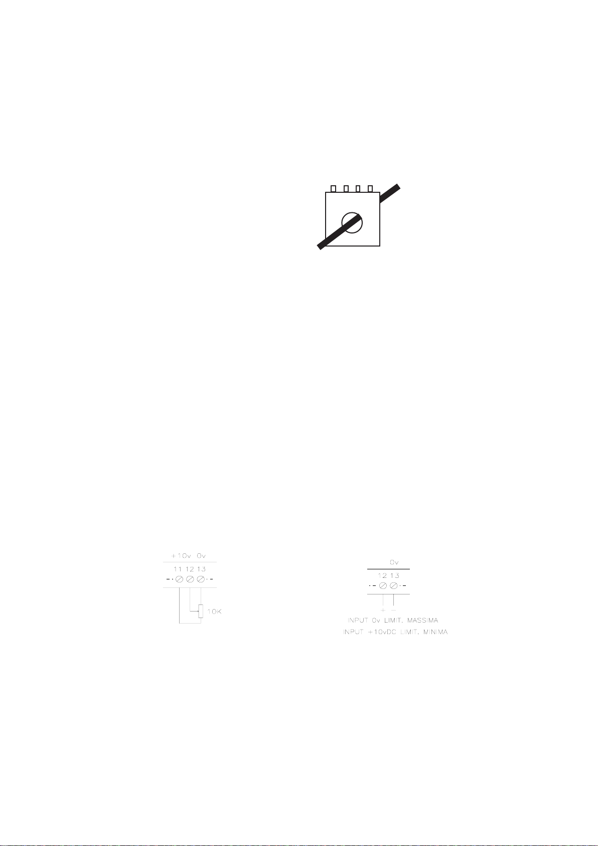
Connection diagrams.........................................................................................................................page. 5
Led signal description ........................................................................................................................page. 6
Trimmer description ...........................................................................................................................page. 6
Dip-switch description ........................................................................................................................page. 6
Command and power connectors description .................................................................................page. 7
380S board setting and command instructions:
Board presetting for the number of motor poles ...............................................................................page. 8
Maximum speed setting - zero revolutions offset ..............................................................................page. 8
Acceleration and deceleration ramp regulation ................................................................................ page. 8
DC signal or potentiometer speed regulation................................................................................... page. 9
Rowan high speed motor couple regulation..................................................................................... page. 10
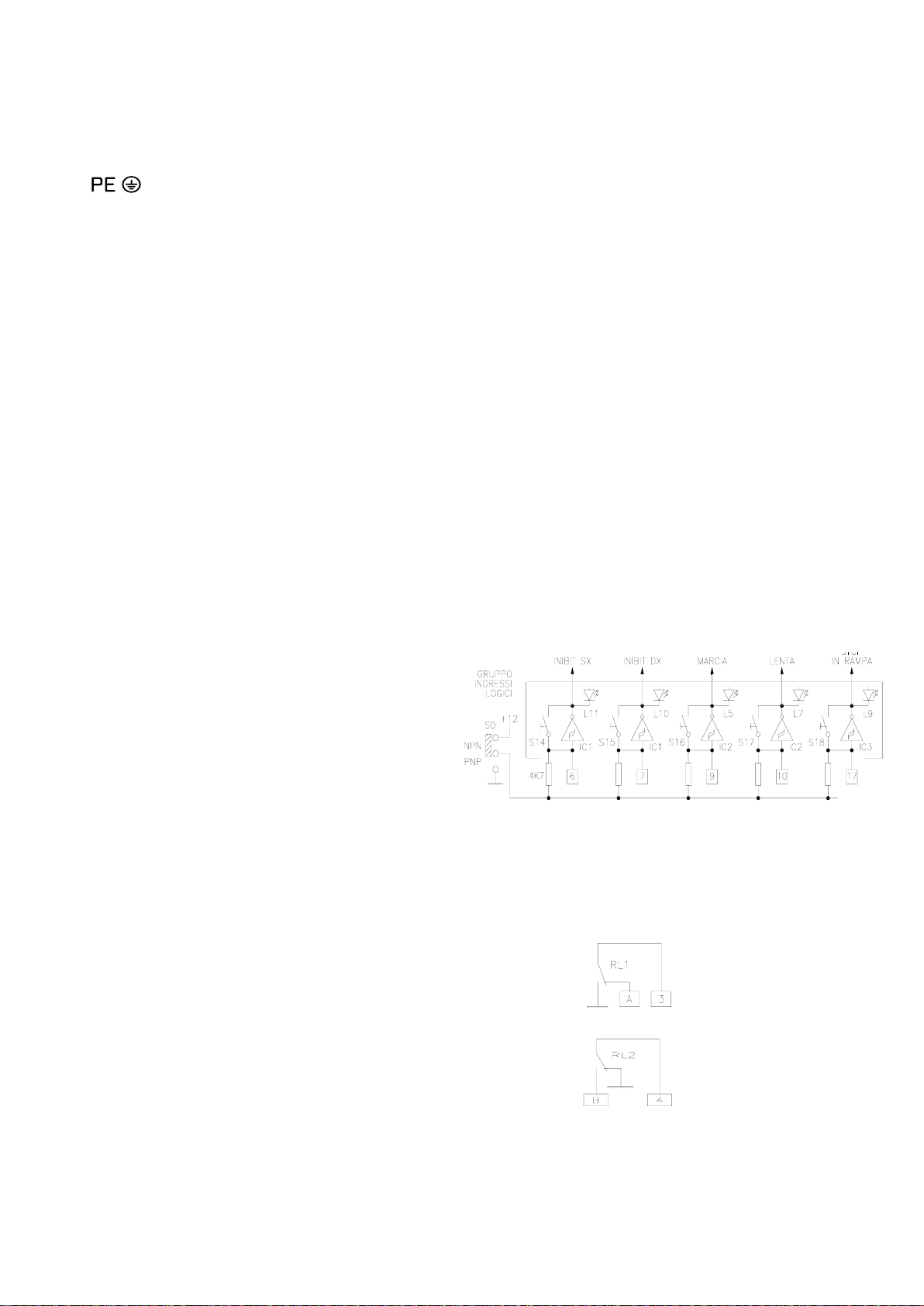
Command inputs description ............................................................................................................page. 11-12
Output description ..............................................................................................................................page. 13
Rowan S series motor connection instructions:
Motor power connector connection ....................................................................................................page. 14
Electrical characteristics table of the motors applicable to the 380S board...................................page. 14
Motor service connector connection...................................................................................................page. 15
Brake connection; table of the power consumption of the 24VDC brake......................................... page. 15
Installationinstructions:
Mechanical installation .......................................................................................................................page. 16
Electrical protection ............................................................................................................................page. 16
Wiring and electromagnetic compatibility..........................................................................................page. 16
Start up ................................................................................................................................................page. 17-18
Troubleshooting..................................................................................................................................page. 18
Default settings and standard settings .............................................................................................page. 18
Applicable diagrams:
Forward/backward movement with pre-stop slowing for precise stopping with the brake command.. page. 19
How to substitute the previous (out of production) boards:
Substitution of Cod. 280S.B/0 and 280R with Cod. 380S................................................................page. 5
Block diagrams .................................................................................................................................. page. 20
Componentslayout............................................................................................................................ page. 21
Maintenance instructions for the S series Rowan motors (high slip type) ................................. page. 22-23
TRANSLATION OF THE TEXT IN THE DRAWINGS ........................................................................pag. 24
Warning!
- ROWAN ELETTRONICA s.r.l. declines any responsibility for any inaccuracies contained in this manual, due to
printing and/or transcription errors. ROWAN ELETTRONICA s.r.l. reserves the right to make any variations that
it considers necessary for better functioning of the product, without prior notification.
- Regarding the data and characteristics mentioned in the manual, a maximum tolerance of 10% has been
allowed, if not otherwise indicated.
- Theproductguarantyisconsideredex-worksandisvalid 6monthsfromthedateofleavingROWANELETTRONICA
s.r.l.
- The electrical equipment could create dangerous situations for the safety of both personnel and objects; the user
is responsible for the installation of the equipment and for the conformity of the installation with the regulations
in force.
- The diagrams contained in this manual are mere examples and should be perfected by the customer according
to their specific needs.
-The equipment must be installed only by qualified personnel, after having read and understood this manual. In
case of doubt, the supplier should be contacted.

ROWAN ELETTRONICA SRL page 3 out of 24
COD.380S
ROWANSSERIESASYNCHRONOUSMOTORVARIABLESLIPBIDIRECTIONALDRIVE
Technical characteristics
-CE product
- Bidirectional driver for high slip Rowan (S series) with a maximum power of 3kW at 380VAC and 1,5kW at 220VAC.
- Standard power supply limits switcheable between 170 / 260VAC and 330 / 500VAC, frequency 50/60 Hz.
- Rowan2-4-6 polemotor speedcontrol presetting witha tachometricaldynamotype 20VDC/2800rpm.
- Operatingwithlinearaccelerationanddecelerationramps,regulatedbytrimmerorexternalpotentiometer from0,1secto
20 sec.
- Speedregulationbypotentiometeror
±
10VDCdifferentialsignal.
- Maximumcurrent/coupleregulationbyinternaltrimmer,0
/
+10VDCsignalorexternalpotentiometer10Kohm;thecurrent/
coupleregulationneedsanexternal4VAC/0.2ATAtobeconnectedinordertomeasurethecurrentconsumedbythemotor.
- Maximumvoltage regulationfor ALQUISTtype operationin thecase ofwinder motors.
- Selectable PNP/NPN logic inputs and commutable NO/NC for, START, STOP IN RAMP, SLOW SPEED, INHIBIT
ROTATION CLOCKWISE/ ANTI-CLOCK WISE.
- differential tachometricaldynamoinput.
- Emergencycontactoutput tosignaloverload, inputlineandmotorphaseloss,Emergency signaldelayablefrom 1secto
15sec.
- Contactoutputforzerocommand relay.
- Led signals of the logic input states, power supply (power on), emergency relay, zero relay and sense of rotation
CLOCKWISE/ ANTI-CLOCK WISE.
- Trimmer regulation of the stability, the acceleration deceleration ramps, maximum and minimum revolutions, maximum
couple and slow speed.
- Protection of the logic and pilot circuits by 0.5A fuse.
- Commandandpowerconnectors.
- Temperaturelimit airenvironment:+5°C ÷+40°C.
- Storagetemperatures: -25°C÷ +70°C.
- Relative humidity 5 ÷ 95%.
- Single version in aluminium container IP20, printed with useful designs for operating control and the setting; base
dimensionsandtemplatefixingsinterchangeablewith mono-directionaldriver390S.
- Interchangeablewiththeprevious boardseries280Re280S.B/0.
Conforms to regulations: CEI EN 60204-1 EN 50081-2 EN 50082-2 EN 61800-3
WARNING: Conformity to these regulations is subject to the connection of filtering devices supplied separately and to
the careful observance, by the installer, of the instructions on page 16.
SESUFDEDNEMMOCERdnaREWOPMUMIXAMfoELBAT
EDOC REWOPXAM ENIL)V042(V022
REWOPXAM -044-514(V083 ENIL)V064
EPYTLGDIPAR DEDNEMMOCER SESUF THGIEW
PHWkPHWkAgK
S083
25,143 021,2
OVERALL DIMENSIONS (in mm)

ROWAN ELETTRONICA SRL page 4 out of 24
WORKING PRINCIPLE
The 380S drive was designed to control the speed of Rowan high slip (S series) motors, which are equipped with a
tachometricaldynamo;itisathreephasevoltageregulatorwithtachometricalfeedback,whichusescontrolleddiodes(SCR)
piloted by a phase chocking system. The voltage that pilots the motor is the result of an analogic process, that maintains
constant revolutionsbymeansof differentialcontroloftheactualmotorspeed,obtainedfrom thetachometricalgenerator,
andthatset byapotentiometer orbyan external analogicsignal.
Combined with a Rowan high slip three phase motor it creates a extremely quiet and uniform system with
constant speed and coupling , from zero until maximum motor revolutions. The choice of controlled diodes
for the power section (moreover already over dimensioned) guarantees reliability in case of extra voltage or
extra current. The 380S driver is bidirectional, the motor speed and sense of rotation are set respectively
to the value and the polarity of the reference signal with a maximum range of ±10VDC.
Theoperationisextendedtoallofthe4quadrants;thecombinedmotor isabletogenerateamotioncouple andbrakingcouple
in both senses of rotation with a peak capacity of up to 3 times the nominal couple . The ROWAN 380S+ high speed motor
system isparticularlyindicatedthereforeforfastmovements(e.g.:axlecontrol)alsowithlarge inertialloads,notneedingany
externaldevice suchas thebrakingresistanceusedfor frequencycontrol of normalasynchronous motors orforDCmotor
drivers.
LED, TRIMMER, DIP-SWITCH POSITIONS

ROWAN ELETTRONICA SRL page 5 out of 24
INSTRUCTIONS FOR THE SUBSTITUTION OF Cod. 280S.B/0 and 280R WITH BOARD 380S
- The 380Sboardisperfectlycompatiblewiththepreviousseries280/0and 280R;forthepowerconnectorconnectionsimply
respect the same connector initials R1 S1 T1 for the line and U1 V1 W1 for the motor; for the command connector
connection, it is sufficient to insert this into the corresponding connector on the 380S as connector numbers 1 to 22 have
thesamefunctions;thelastnecessaryoperation isthestandardpresetpositioningofthedip-switches:S1-S2-S5-S6-
S14-S15-S16-S17-S19CLOSED S3-S4-S8-S12-S18-S20OPEN-S0intheNPNposition;inthiswaythe380Sboard is
standardly preset in the same way as the 280S.B/0 or 280R.
- Ifthe boardto besubstituted issetdifferentlyfromfactory standard,bear inmind thatthe dip-switches andthe trimmer
withthesameinitialsonthe380Shavekeptthesamefunctionsandthereforeitissufficienttosettheminthesameway
asthe 280S.B/0and280R.
CONNECTION DIAGRAMS
Operating with board in standard preset as described on page. 18
GENERAL CONNECTION DIAGRAM BASE CONNECTION DIAGRAM

ROWAN ELETTRONICA SRL page 6 out of 24
LEDSIGNALSDESCRIPTION
L1 CLOCKWISE rotation (Motorrotating fieldrotationsense):
On with reference to negative speed indicates that the motor is rotating CLOCKWISE .
On with reference to positive speed indicates that the motor, in ANTICLOCKWISE rotation is developing braking
couple.
L2 ANTICLOCKWISE rotation (Motorrotantingfield rotationsense):
On with reference to positive speed indicates that the motor is rotating ANTICLOCKWISE.
Onwithreferenceto negativespeed indicatesthatthe motor,inCLOCKWISE rotationisdeveloping bakingcouple.
L3 Zero relay on: On indicates that the zero relay connected to connectors 3-5 has excited.
L4 Power on: On indicates that the board and piloting circuit power supply are present.
L5 Start:Onindicatesthe presenceofanactivecommand atconnector9,thereforewhenmotorrotationisoff,indicates
thatmotorrotationisnotenabled.
L6 Emergency: Onindicates aproblem causedby overload,lossoflinephase, lossof motorphase; inthiscasemotor
startenableisdisabledandtheexternallyconnectedemergencyrelayisactivated;thissituationisautomaticandcan
only be unblocked by disconnecting the board power supply; if led L6 comes on consult paragraph
"TROUBLESHOOTING"onpage. 18.
L7 Slowinsertion:
Onindicatesanactiveslowrotationenablecommandpresentatconnector10.Inthiscasethemotorpassesfromthe
setpotentiometer orexternal signalspeed ±10VDCto anindependent speed,presettable bytrimmer P1;the speed
change occursbymeansof rampssetby trimmersP2- P3.Theslowrotationsenseisdetermined bythereference
voltage polarity present at connector 14 and can be taken at connectors 1 or 2.
L9 Stop in ramp: Onindicatesthe presenceofan activecommand atconnector 17;inthis casethemotor decelerates
with the set deceleration ramp until at zero revolutions ; L9 must be off for restart to be allowed.
L10 ClockwiserotationInhibited :Onindicatesthepresenceofanactivecommandatconnector7inhibitingthemotor
to rotate in the clockwise motor rotating field.
L11 AnticlockwiserotationInhibited: Onindicatesthepresenceofanactivecommandatconnector6inhibitingthemotor
torotate inthe anticlockwise motorrotating field.
TRIMMERS DESCRIPTION
TRIMMERS ACCESSIBLE WITHOUT REMOVING THE LID
P1 Slowspeedregulation(seepage12).
P2-P3 Acceleration/decelerationrampregulation(seepage8).
P4 Maximumrevolutionregulation(seepage8).
P6 Zerorevolution Off-Setregulation (see page8).
P8 Maximumcouplelimitationregulation(seepage10).
P10 Zerorelay SET-POINTregulation(seepage13).
P15 Stabilityregulation(seeTROUBLESHOOTINGpage18).
TRIMMERS ACCESSIBLE REMOVING THE LID (authorised personnel only)
P5 4 pole motor preset - 1400g/m (see page 8)
P9 Minimum couple limitation regulation (see page 10).
P11 Emergencyinterventiondelay regulation (standardsetting 7s - minimum1s - maximum15sall clockwise).
P12 Zero revolutions hysteresis zone regulation (clockwise increases zero rotation precision).
P7-P16 Stabilityregulation (seeTROUBLESHOOTING page18).
DIP-SWITCHDESCRIPTION
S0 logic input settings NPN/PNP.
S1-S2 In/outregulationrampsswitching(see page8).
S3 Ramp time switching (see page 8).
S4 Ramp at S (see page 19).
S5 Motorpolarityadaptation (seepage 8).
S6 Reply/stabilityregulation(seepage 18).
S8-S12 Couple control setting (see page 10).
S14-S15-S16-S17-S18 Logic command input contact NO/NC settings.
S19 Speedsetby potentiometer or±10VDC differential signalselection (see page 9).
S20 Power supply frequency selection 50Hz / 60Hz (see page 17).

ROWAN ELETTRONICA SRL page 7 out of 24
POWER CONNECTOR DESCRIPTION
R1 - S1 - T1 Standardthreephasepowersupplyswitchableinranges 170÷260VAC and330÷500VAC. Makesureto
setthevoltagechangecorrectlybeforepoweringtheboard.Powersupplyfrequency50Hz(dip-switchS20
open) or 60Hz (dip-switch S20 closed). See instructions on page. 17
EMIfilterground connection;connectto thegeneral protectionconductor the line inductancecouplingfor
thereduction ofconducted emissions(see instructionson page.16).
WARNING ! The anti EMI filter works with a small ground dispersion current that could make too sensitive
differentialsinterveneatthemomentofpowerup.Itisrecommendedthatimpulsivecurrentdifferentialsare
used.
U1 - V1 - W1 Regulatedmotorvoltageoutput. Presetthestarortrianglemotor accordinglytotheirplatedataandpower
supplyrequirements.(seepage17).
COMMAND CONNECTOR DESCRIPTION
Referencevoltages:
1 -10VDC referencepower supply forexternal potentiometers (maximum load5mA).
2 +10VDC referencepower supply forexternal potentiometers (maximum load5mA).
524VDC50mA external emergency relay andzero relay coilpower supply.
8 0VDCnegativecommonreference.
11 +10VDC coupleregulationpotentiometerpowersupplyreference.
13 0VDCnegativecommonreference.
16 0VDCnegativecommonreference.
0V 0VDC TA connection reference.
Analoguevoltageinputs:
14 Analoguevoltage inputsforslowspeedmotor directionsense selection.
15 ±10VDCspeedreferenceanaloguevoltageinput.
TA TAreference input withrange 4VAC /0.2A.
Differentialvoltageinputs:
21 - 22 Tachometricaldynamo20VDC/2800gmdifferentialvoltageinputreference.
23 - 24 Speedreference±10VDCdifferentialvoltageinput,47kohminputresistance.
(inputactivatedwithdip-switchS19open).
Logicinputs:
6Logicinputwiththefunction
ANTICLOCKWISE ROTATION inhibit.
7Logicinputwiththefunction
CLOCKWISE ROTATION inhibit.
9 STARTcommandlogicinput.
10 SLOW SPEED commandlogicinput.
17 STOP IN RAMP commandlogicinput
Externalrelaycontactsoutputs:
3Zero relay COMMON contact.
AZero relay NC contact.
NOcontactconnectedinternallyto ground.
4Emergency relay COMMON contact.
BEmergency relay NC contact.
NOcontactconnectedinternallyto ground.
ExternalpotentiometerACC./DEC.rampsregulationconnectors:
18 Externalpotentiometeracceleration/decelerationregulationrampscommonconnector.
19 ACCELERATIONRAMP(470kohm)externalpotentiometerconnectionconnector.
20 DECELERATIONRAMP(470 kohm)externalpotentiometerconnection connector.
Contattorelè
dizero
Contattorelè
diemergenza

ROWAN ELETTRONICA SRL page 8 out of 24
PRESET OF THE BOARD FOR THE NUMBER OF MOTOR POLES
- If the motor is 4 or 6 pole close dip-switch S5.
- If the motor is 2 pole open dip-switch S5.
- If the motor is double polarity (2 pole / 4 pole) open S5.
INTERNAL SETTING OF THE MAXIMUM SPEED
Thissetting isalreadycarried outduringthetestingstage for2and4pole motorsandisonlyadjusted bytheinstalledinthe
case of 6 pole motors, double pole motors or if the board has been off set. In such cases proceed as follows:
- Apply a +10VDC or -10VDC signal to connector 15.
- If the motor is 2 pole (S5 open) regulate P4 for a maximum speed of 2800 rpm (20 VDC tachometrical dynamo).
- If the motor is 4 pole (S5 closed) regulate P5 for a maximum speed of 1400 rpm (10 VDC tachometrical dynamo).
- Ifthemotoris6pole(S5closed) regulateP5foramaximumspeedof 800rpm (5,7VDC10VDCtachometricaldynamo).
- Ifthemotorisadoublepolarity(S5open)regulateP4 foramaximum2polespeedof 2600rpm.(18,5VDCtachometrical
dynamo);forthisapplication;itisnecessarytoconnectinserieswithpositivespeedregulationpotentiometer (10Kohm)
connector a 10K ohm 0,5W resister. This resistor is short circuited when the motor is commuted to 2 pole mode.
- P4 - P5 regulated in a clockwise sense increases speed.
Warning! Donotexceedwiththeregulationtheindicatedmaximumspeedsasthiswouldsendthemotorinoverload
(evenwhen unloaded)andin anycase would causetime response delays.
ZERO REVOLUTION OFFSET SETTING
- Give zero volts to connector 15 or close stop in ramp.
- RegulateP6 until themotorstops.
ACCELERATION/DECELERATION RAMP REGULATION
Internalrampregulation
- Close dip-switches S1 - S2.
- P2regulatesthedecelerationramp(clockwiseregulationincreasesramptime).
- P3regulatesthe accelerationramp(clockwise regulationincreasesramp time).
- S3open fixesthe rampregulationfieldfromminimum 0,1secto maximum1,5 sec.
- S3 closed fixes the ramp regulation field from minimum 1,5 sec to maximum 20 sec.
Externalaccelerationrampregulation
-The connection must be made with screened cable and as close as possible to the driver.
- opendip-switchS2;
- trimmerP3 isin serieswith theexternal potentiometer.
- with S3 open and P3 at maximum external ramp regulation from 1,5sec (0kW) to 3sec (470kW).
- with S3 closed and P3 at maximum external ramp regulation from 20sec (0kW) to 40 sec (470kW).
- withP3atminimumexternalaccelerationrampregulationfieldasinternalregulationramps.
Externaldecelerationrampregulation
-The connection must be made with screened cable and as close as possible to the driver.
- opendip-switchS1.
- trimmerP2 isin serieswith theexternal potentiometer.
- with S3 open and P2 at maximum external ramp regulation from 1,5sec (0kW) to 3sec (470kW).
- with S3 closed and P2 at maximum external ramp regulation from 20sec (0kW) to 40 sec (470kW).
- withP2atminimumexternalaccelerationrampregulationfieldasinternalregulationramps.

ROWAN ELETTRONICA SRL page 9 out of 24
EXTERNAL POTENTIOMETER SPEED REGULATION
- To activate this type of regulation dip-switch S19 must be closed.
- The load at connectors 1-2 must not exceed 5mA (potentiometerresistance minimum5kW/maximum 100kW).
- Optimum potentiometer value 10kW (min 3kW - max 100kW) .
-Connectionmustbe made withscreenedcable.
EXTERNAL ±10VDC SIGNAL SPEED REGULATION
(inputactivated withdip-switch S19open)
- To activate this type of regulation dip-switch S19 must be open.
- Differentialinputpilotablebyinterfaceboard,positioninginstruments,PLCorcomputerwithguaranteedgalvanicisolation
fromthehightensionandimmunefromcommoninterference.
- Connectionmustbe made withscreenedcable.
SENSE OF ROTATION SENSE OF ROTATION
SENSE OF ROTATION SENSE OF ROTATION STATIONARYMOTOR
MAXIMUMSPEED MAXIMUMSPEED

ROWAN ELETTRONICA SRL page 10 out of 24
ROWAN MOTOR COUPLE REGULATION WITH AMPEROMETRICAL FEEDBACK
Anexampleoftheuseofthisfunction;iswhenaRowanmotordrivestangentiallytowindorunwind abobbinwithacontrollable
pull.
Themaximum speedisset bythe revolution regulation potentiometer, andthe maximumpull bythe couple regulation
potentiometer, which limits the controlled motor current using a closed loop with an amperometric transformer (TA); the
maximum couple regulation potentiometer field may be set by trimmer P8 MAXIMUM COUPLE and by the use of the TA
(current plug connected and a number of wire passes) which must be connected to connectors TA-0V.
Theboardisdesignedtooperatewithanamperometricaltransformertype151/110witharangeof4VAC.2AsuppliedbyRowan
Elettronica. Characteristics TA 151/110 with ONE WIRE PASSING:
Plug 1 - 2 = maximum output 25A
Plug 1 - 3 = maximum output 50A
Plug 1 - 4 = maximum output 100A
The maximum load of the various plugs may be divided by the number of wire passes; for example, if plug 1 - 2 is used and
5wirepassesaremadethroughtheTA,themaximumoutputwillbeacurrentof5A;choosetheTAplugandthewirepasses
accordinglytothe Rowanmotor used.
This function may be used together with external apparatus such as PLC or with the Rowan Cod. 274 servodiametric
instrument(inthecaseofwinder/unwinderwithcontrollablepullandbobbinaxlemotor);thisapparatusmaysupply,bymeans
ofa0/+10VDCsignal,themaximumspeedsignal(connectors23-24)andthatofmaximumcouple(12-13),insteadof manual
potentialregulation.
COUPLE REGULATION using internal trimmer:
- toinserttheinternallimitationregulationcloseS8-S12;
- P8regulatesmaximummotorcurrent;
- P9regulatesminimum current(setto zeroasstandard);
- P8-P9 in a clockwise direction increases the current.
COUPLE REGULATION using external trimmer or D.C. signal:
- toinserttheexternallimitationregulationcloseS12andopenS8.
- theoptimumpotentiometervalueis10Kohm (minimum3Kohm-maximum100Kohm).
- Input12 hasa50Kohmloadresistance andispilotablebyinterfaceboard,PLCandcomputerwithguaranteedhightension
isolation.The externalpotentiometer orDCsignalregulationfield isset by trimmerP8 (maximum)eP9(minimum).
- theconnectionmust bemadewith screenedcable;
ALQUIST SYSTEM COUPLE REGULATION
Thistypeofregulationisusedforexample,forpullcontrolofthematerialtobewoundbythemotorappliedtothebobbinaxle,
whoseminimumandmaximumdiametervariationdoesnotexceedtheratioof1/3;inthiscasethecoupleisregulatedlimiting
motorvoltage andnot thecurrent,thereforetheTA connectionis omitted.
Theregulationpossibilitiesarethesameasdescribed foramperometricfeedbackbearinginmindthatthemaximummustbe
decreasedconsiderably bytrimmerP8 (regulatingclockwise) tore-enterin thecurrent regulationfield.
WARNING: bear in mind that, when regulating couple, in blocked rotor operation, Rowan motor maximum current in
continuousoperationmust beatleast 20%lessthan the nominalcurrent.
1 2 3 4
EXTERNAL REGULATION by
POTENTIOMETER EXTERNAL REGULATION
by DC SIGNAL

ROWAN ELETTRONICA SRL page 11 out of 24
COMMAND INPUTS DESCRIPTION
START COMMAND
- The activation of the start command is signalled by led L5.
- Whenthe start isactivated,itenables motor rotationin accelerationrampuntil theset speed.
- Whenthestartisdisabled,itstaticlyremovesmotorvoltage(ifthemotorisrotatingitwillnotbrake)
zeroes the ramps and excludes the other commands.
If the start is commanded by a pure contact (see the diagram at the side):
- Set S0 to the NPN position and close dip-switch S16.
- To activate the start close the contact.
- Todisable thestartopen thecontact.
If the start is commanded by NPN/PNP transistor logic (see diagram fig.1 page.13):
- If NPN logic, set S0 to the NPN position and open dip-switch S16.
- If PNP logic, set S0 to the PNP position and open dip-switch S16.
- To activate the start give a positive output (min 8VDC max 24VDC).
- To disable the start give 0VDC.
- The opening / closing of dip-switch S16 causes, in any case, the activation / deactivation and
therefore gives the possibility to adapt the input to any type of both NO and NC command.
STOP IN RAMP COMMAND
- The activation of the stop in ramp command is signalled by led L9.
- When the stop in ramp is activated, it causes motor to decelerate from the set speed until zero
revolutions, with the ramp set by P2.
- Whenthestopinramp is deactivated,enablesmotor rotation untiltheset speed,withthe ramp
set by trimmer P3.
If the stop in ramp is commanded by a pure contact (see the diagram at the side):
- Set S0 to the NPN position and open dip-switch S18.
- To activate the stop in ramp close the contact.
- Todisable thestop inrampopen thecontact.
If the stop in ramp is commanded by NPN/PNP transistor logic (see diagram fig.1 page.13):
- If NPN logic, set S0 to the NPN position and close dip-switch S18.
- If PNP logic, set S0 to the PNP position and close dip-switch S18.
- To activate the stop in ramp give a positive output (min 8VDC max 24VDC).
- To disable the stop in ramp give 0VDC.
- The opening / closing of dip-switch S18 causes, in any case, the activation / deactivation and
therefore gives the possibility to adapt the input to any type of both NO and NC command.
INHIBIT ANTICLOCKWISE ROTATION COMMAND
- The activation of the inhibit anticlockwise rotation commandis signalledbyled L11.
- Theinhibitanticlockwiserotationcommand excludesclockwiserotationbrakingandanticlockwise
start.
- Thedisabledinhibitanticlockwiserotationcommand restoresbidirectionaloperation.
If the inhibit anticlockwise rotation is commanded by a pure contact (see the diagram at the
side):
- Set S0 to the NPN position and close dip-switch S14.
- Toactivate theinhibit anticlockwise rotationclosethe contact.
- Todisabletheinhibit anticlockwiserotationopenthecontact.
Iftheinhibitanticlockwiserotation iscommandedbyNPN/PNPtransistorlogic(seediagram
fig.1 page.13):
- If NPN logic, set S0 to the NPN position and open dip-switch S14.
- If PNP logic, set S0 to the PNP position and open dip-switch S14.
- To activate the inhibit anticlockwise rotation give a positive output (min 8VDC max 24VDC).
- Todisabletheinhibit anticlockwise rotation give0VDC.
- The opening / closing of dip-switch S14 causes, in any case, the activation / deactivation and
therefore gives the possibility to adapt the input to any type of both NO and NC command.

ROWAN ELETTRONICA SRL page 12 out of 24
INHIBIT CLOCKWISE ROTATION COMMAND
- The activation of the inhibit clockwise rotation commandis signalledbyled L11.
- Theinhibitclockwiserotationcommand excludesanticlockwiserotationbrakingandclockwisestart.
- Thedisabledinhibitclockwiserotationcommand restoresbidirectionaloperation.
Iftheinhibitclockwiserotationiscommandedbyapurecontact(seethediagramattheside):
- Set S0 to the NPN position and close dip-switch S15.
- Toactivate the inhibit clockwise rotation closethecontact.
- Todisabletheinhibit clockwiserotationopenthecontact.
Iftheinhibitclockwiserotation iscommandedbyNPN/PNPtransistorlogic(seediagramfig.1
page.13):
- If NPN logic, set S0 to the NPN position and open dip-switch S15.
- If PNP logic, set S0 to the PNP position and open dip-switch S15.
- To activate the inhibit clockwise rotation give a positive output (min 8VDC max 24VDC).
- Todisable theinhibit clockwise rotation give0VDC.
- The opening / closing of dip-switch S14 causes, in any case, the activation / deactivation and
therefore gives the possibility to adapt the input to any type of both NO and NC command.
SLOW SPEED COMMAND
- The activation of the slow speed command issignalled by led L7.
- Whentheslowspeedcommand isactivated,itexcludesspeedsettingatconnector15orconnectors
23-24 andselectsspeedsettingbymeansoftheinternaltrimmerP1;thesenseofrotationisdetermined
by thevoltagepolarityappliedtoconnector14andthespeedissettablefromzeroto70%ofmaximum
motor speed; the passing from set speed to slow speed and vice versa is subject to the acceleration
/decelerationramps set byP3/P2.
- Thedisabled slow speed command restores speedsetting byexternalreferences.
If the slow speed is commanded by a pure contact (see the diagram below):
- Set S0 to the NPN position and close dip-switch S17.
- To activate the slow speed close the contact.
- Todisabletheslow speed openthecontact.
If the slow speed is commanded by a pure contact (see the diagram below):
If the slow speed is commanded by NPN/PNP transistor logic (see diagram fig.1 page.13):
- If NPN logic, set S0 to the NPN position and open dip-switch S17.
- If PNP logic, set S0 to the PNP position and open dip-switch S17.
- To activate the slow speed give a positive output (min 8VDC max 24VDC).
- Todisable theslow speed give0VDC.
- Theopening/closingofdip-switchS17causes,inanycase, theactivation/deactivationandtherefore
gives the possibility to adapt the input to any type of both NO and NC command.
SLOWSPEEDSLOWSPEED

ROWAN ELETTRONICA SRL page 13 out of 24
EXTERNAL INPUT /OUTPUT NPN/PNP (PLC) LOGIC CONNECTION DIAGRAM
Fig. 1
OUTPUTDESCRIPTION
The voltage supplied by the device to the zero external relay is 20Volt and the power line is 380Volt (or 220Volt if
presetted); for that reasonì, if the power line goes down over than 15% of the voltages indicated, we can have
troubleshooting on the relay mentioned. On that case it is necessary to supply the external relay by an opportune
indipendent source like those on drawnings Fig.1.
MOTOR SPEED SENSING OUTPUT
If the output is connected to a relay (zero relay) as shown in the diagram at the side:
- Connectarelay 24VDCmaximum 50mA.
- EachtimethemotorspeedexceedsthespeedthresholdsetbytrimmerP10thelampL3lightsandtherelay
closes.
- Trimmer P10 (zero relay set point) sets the relay excitation for a motor speed field of
30rpmto1900rpm.
- Thezerorelay may beused,for example, fortheautomatic release of thestart relay when themotor
isnotrunning.
If the output is connected to NPN/PNP logic inputs (see diagram fig.1):
- If NPN logic, Each time the motor speed exceeds the speed threshold set by trimmer P10 the lamp
L3 lights and the PLC input passes from 24VDC to 0VDC.
- IfPNPlogic,EachtimethemotorspeedexceedsthespeedthresholdsetbytrimmerP10thelampL3lights
and the PLC input passes from 20VDC to 0VDC.
EMERGENCY OUTPUT
If the output is connected to a relay as shown in the diagram at the side:
- Connect a relay 24 VDC maximum 50mA.
- Therelay closes whenthe board ispowered andstaysclosed duringnormaloperation.
- Inanemergencysituation,ledL6lights,andtherelayopens(seetroubleshootingpage18).It
is necessary to remove board power supply in order to recover the original situation.
If the output is connected to NPN/PNP logic inputs (see diagram fig.1):
- If NPN logic, in an emergency situation when led L6 lights and the PLC input passes from
0VDC to 24VDC.
- If PNP logic, in an emergency situation when led L6 lights and the PLC input passes from
20VDC to 0VDC.
INPUTS INPUTSOUTPUTS OUTPUTS

ROWAN ELETTRONICA SRL page 14 out of 24
ROWAN SSERIES MOTORS CONNECTION INSTRUCTIONS
POWER CONNECTOR CONNECTION
Thepowerconnectorconnection,eventhoughpassingthroughthespeedcontroldriver,remainsasanormalasynchronous
threephasemotor,therefore, ifindicatedbythemotor platedata:
ELECTRICAL CHARACTERISTICS TABLE OF THE MOTORS APPLICABLE TO THE 380S BOARD
For motor overload / overheating protection the use of the thermic sensor contact located on the motor windings and
available at the service connector is quite sufficient. (see page 15). The thermic sensor exists on all motors apart from
the MEC 63 which must be protected by a thermic valve set to a current of 15% more than the nominal value.
SREWOPROTOM CEM EZIS
LANIMONROTOM TNERRUC LANIMONI SREWOPNAF
caV032caV004LAIXA LLORCS NAF
PHWKAAAVAV
51,011,0366,19,06104
52,08
1,0179,11,16104
5,073,0081,38,16104
157,00965,39155
25,1001115,60455
32,2211*904001
43 L211*2104001

ROWAN ELETTRONICA SRL page 15 out of 24
SERVICE MOTOR CONNECTOR CONNECTION
1-2Tachometricaldynamo:itispossibletoobtainthevoltagefromtachometrical
dynamo which is fitted to the motor axle from this connector. It supplies a DC
voltage,equalto20VDCat 2800rpm,directlyproportionaltothemotorspeed;
forthisreason itcan,as well asbeing connected tothe driver formotor speed
control, be used for analogue rev. counters with display or other servo-
mechanisms,providedthattheoverallloaddoesnotexceed3Kohm(maximum
dynamo current 10mA). To avoid interference, it is wise to connect the
tachometricaldynamousing screenedcable,especially whenitisclosetothe
powercable.
3-4Coolingfan:itisnecessarytosupplythisconnectorwith220VACfortheseparatemotorcooling;thisshouldbepresent
alsowhenthemotoris notrunningas tomakeuse ofsuchtimesformotor cooling.Insome highpowerRowan motorsfitted
with three phase cooling fans, the power is supplied directly from the motor base to the cooling fan. For cooling fan power
consumptionconsult thetable on page14.
5 - 6 Thermic sensor: It is a normally closed contact which opens when the motor windings exceed 150°C, safety limits
correspondingtoclassH(180°C).Itisusedasanemergency openingthestartrelaybearinginmindthatthemaximumload
of the contact is 1A - 230VAC.
Warning! in the ROWAN MEC 63 motor service connector connectors 5 - 6 are not present (the 63 motor has no thermic
sensor).
BRAKECONNECTION
Rowan motors may be supplied, on request, with an electromagnetic brake. This would mean a purposely built motor
withalengthened axle and brakefitted to the frontpart, supported by abell shaped cover thatreproduces normal flanging.
The brake is a Spring type: it is necessary to remove the brake power supply to stop the motor axle. It is used as a safety
brake if the power supply should be lost, in the case of over head loads such as bridge cranes, cranes etc. (verify whether
it would be necessary to adapt the air gap at 0,3mm ± 0,005).
This brake operates at 24VDC and is powered by a single connector or a connector found on the bell shaped front brake
holder.Itis alwaysconvenientto connectadiode orR/Cin paralleltothe brake,aboveall when closeto equipments which
are particularly subject to interferences.
It is necessary to bear in mind that the flywheel diode has a maximum filtering efficiency, but it delays spring
brake insertion.
Note: for a better use of the brake, Rowan Elettronica suggests the following connection to the C321S device:
This device gives a 33÷37Vdc starting voltage and a succeeding 21÷23Vdc maintainance voltage. In this way the brake
release is sped and the overtemperature, during the continuous service, is avoided.
TABLEOFTHEPOWERCONSUMPTIONOFTHE24VDCBRAKE
SEDOCNOITACIFITNEDIDNASCITSIRETCARAHCNOITPROSBA/ELPUOCEKARB
ROTOM
EKARBGNIRPS
EUQROTNOITPROSBAEPYT GNIKCOLBNU REVEL
EKARB GNITRATS EMIT
EKARB EMITGNIPPOTS
mNW .doC.doCsmsm
17/365,45110K17/36MRF/7153
0880220K08MRF/5356
001/09610340K11019MRF11019AVEL0409
L211/211535450K211MRF211AVEL05021
TACHO-GEN.FAN THERMIC
PROBE
BRAKE
BRAKE
command

ROWAN ELETTRONICA SRL page 16 out of 24
INSTALLATIONINSTRUCTIONS
MECHANICAL INSTALLATION
Please note the following warnings while installing the driver:
- Check that the environment in which it is to be installed complies with the environmental characteristics as described
on page 3 (temperature - humidity - protection degree).
- Allowmaximumairflowforcooling,avoidingdriveroverlayingandleavingaspaceofatleast100mmbothaboveandbelow
the driver and at least 50 mm at the sides.
- Avoid excessive vibrations and collisions.
- Leaveenoughspaceforanyanti-EMIfilters(seethefollowingparagraph).
Thecod. 380S seriesboardsworkcorrectly whenthetemperatureson their casesandinside their housingcabinets
arebetween-5°C e +40°C; temperaturesaboveorbelowcould cause operatinganomalies, speedcontroldriftsand,
whentoohigh,theycouldcausebreakages;itisthereforeadvisabletopositiontheboardawayfromheatsourcesand
toventilatethecabinetifenvironmental temperatures are high.
ELECTRICAL PROTECTION
TheCod.380Sboardisprovidedwithaprotectiondevicewhichinterveneswhenthemotorisoutoftachometricalcontrol,such
as in the case of overload, power-line and motor phase loss, tachometrical loss and tachometrical polarity inversion; The
emergencyinterventionremovesmotorrotationenableandexcitestheemergencyexternallyconnectedrelay;theboardpiloting
circuit is also protected by a series of 0,5A fuses located on the lower board which houses the power connectors.
Forthepoweramperometricprotectionitisnecessarytoprovideexternalfusesforsortcircuitprotectionof20AofthetypeGL
FAST (and thermic circuit breaker calculated for a current of 15% above the nominal current for MEC 63 motors only).
Thethermic sensor incorporatedin the motormay beusedas analternative to thethermic relay.
ToselectpotentiometerorDCsignaluserelayswithcurrentbasecontacts;absolutelyavoidtheuseofauxiliaryrelaycontacts
forthistypeofoperation.
WIRING AND ELECTROMAGNETIC COMPATIBILITY
Inorder tolimitthe disturbancesinduced intheconnection cables:
- Avoid passing the command connector connection cables in the same cable run as the power cables.
- Connectpotentiometers,tachometricaldynamo, DCsignals usingscreenedcable.
- Connecteach endof thescreen separatelyto thecommon groundpoint ofthecabinet.
- Avoidgroundloops.
- Toavoidconductedemissionsonthepowerlineandimproveimmunitytothistypeofdisturbances,connectthefilterinductance
and connect the connectors and PE to the common ground point .
Warning! Theanti-EMIworkswithasmallgrounddispersioncurrentwhichmaycausetoosensitivedifferentialstointervene
atthemomentof power-up.Theuseofdifferentials isrecommendedforimpulsivecurrent.
RowanElettronicamaysupplythecompleteANTIEMIonrequest: theinductancesarechosenaccordinglytothenominal
currentofthe appliedRowanmotor,orthesumof themotors.Asingle inductancemayservemorethanonedriver inparallel.
The external EMI filter is costituted by an inductance L and by three EMI condensers type Cx; the condensers are supplied
in plastic box (dim. 65x35x29mm) along with connectors type Faston named CXT.ROW0.15.440.
See drawing for connection:
If a rephasing circuit, is needed, this must be mounted before the ANTI EMI filter, otherwise the emission reduction will not
function.The insertionof rephasingcapacitorsalsoreducesEMI emissions.
CODE AND CHARACTERISTICS OF THE ANTI EMI FILTER THREE PHASE INDUCTANCES
FORMEC63MOTORONLY
TREEPHASE
INDUCTANCE
FOR MEC 63 MOTOR ONLY
REPHASING
CAPACITORS
SPECIFIC TELEBREAKER TO
INSERTCONDENSERSTYPELC1
DFK11 TELEMECANIQUE
TREEPHASE
INDUCTANCE
ECIDOC ETNERROC AMISSAM ()A
AZNATTUDNI ()Hm )mm(INOISNEMID
HBL
5,1.A01.TPMI015.152106021
90.A02.TPMI029.005157051
CODE MAXIMUM
CURRENT
(A)
INDUCTANCE
(mH)
DIMENSIONS
(mm)

ROWAN ELETTRONICA SRL page 17 out of 24
START-UP
PRELIMINARY OPERATIONS:
Priortofixingtheboard,setthethreevoltagechangersaccordingto
thepowersupplyandthedip-switchS20accordingtothefrequency
(50Hz/60Hz),bearinginmindthattheboardleavesRowanpresetfor
thehighestvoltagerangeandforthefrequency of50Hz;inorder to
access the voltage changers and the dip-switch S20, found on the
middle board. It is necessary to remove the plug connectors and
remove the printed cover; the voltage changers are set in the
followingway:
C380S.B/0X.C
( STANDARD VERSION)
Preset board
for power supply field
170VAC/260VAC
Preset board
for power supply field
330VAC/500VAC
F1 - F2 - F3 0,5 A pilot protection Fuses.
If the power supply frequency is 50Hz, open dip-switch S20.
If the power supply frequency is 60Hz, close dip-switch S20.
The rest of the setting is carried out on the top board were the trimmers, dip-switches and leds are to be found.
To put the board into minimum operation carry out the electrical connections shown in the base diagram on page 5.
(potentiometerspeedcontrol)andfollowthe instructions below:
Set dip-switchS5 accordingto themotorpolaritytobe regulated:
2pole motor /dip-switch S5open
4 - 6 pole motor / dip-switch S5 closed
Inthecaseof6polemotorsitisnecessarytolaterregulateP5inaclockwisedirectionuntilthetachometricaldynamogenerates
about5,7 VDCwith thepotentiometer or DCsignal atmaximum.
Choosetheaccelerationanddecelerationramprange:
Dip-switchS3 open TrimmerP2regulationfield minimumdeceleration 0,1sec-maximum1,5sec.
TrimmerP3regulation field minimumacceleration0,1sec -maximum1,5sec.
Dip-switch S3 closed TrimmerP2regulationfield minimumdeceleration1,5sec-maximum20 sec.
TrimmerP3regulation field minimumacceleration1,5sec-maximum20 sec.
Connectthestartasshowninthebaseconnectiondiagramonpage5;bearinginmindthatthecontactmustbeclosedformotor
rotationenable.
Connect the revolution regulation potentiometer atconnectors 2-15-8;withthewiper15 towardsconnector 8(0VDC)the
motorwill be idle;with the wiper15 towards connector 2(+10VDC) the motorwill rotate atmaximum speed.
Settheremainingdip-switches:S1-S2-S6-S14-S15-S16-S17-S19closedandS4-S8-S12-S18open.
Carry out the motor board connectionsaccording tothefollowing instructions(also seepage14-15):
Connectin a staror triangleway, according tothe lineand motor platedata; connectthe motor toearth.
Thetachometricaldynamosignal,whichis tobeconnected tothe380S boardconnectors21 -22, isobtainedfrom themotor
service connectors 1 - 2.
Thecoolingfanpowersupply(220VAC-50Hz)mustbeconnectedtothemotorserviceconnectors3-4;Thecoolingfanpower
supplymustnotbeconnectedtogetherwiththestartbutconnectedtothecommandpanel;thistogivethepossibilityofcooling
themotoreveninthemomentswhennotrunning;formotorswiththreephasecoolingfanstheconnectioniscarriedoutdirectly
tothe fanbase.
Thethermicsensorisconnectedtothemotorserviceconnectors5-6,thishasanormallyclosedcontact(1A-230VAC)which
shouldbeconnectedinserieswiththeemergency;itislocateddirectlyonthemotorwindings andopensifthemotorwindings
temperaturereachesthe safety limitsfor the tropicalizedwindings in classH(150°C).

ROWAN ELETTRONICA SRL page 18 out of 24
TO MAKE THE MOTOR ROTATE:
Regulate the potentiometer in such a way that its wiper connected to connector 15 is in short circuit with connector 8.
Powerthe board,the motormust beidle.
ThelampL4on(poweron)indicatesthepresenceofthepilottingboardpowersupply,thelamp L5onstartindicatesmotor
rotationisenabled.
Turningthepotentiometer,themotorshouldfollowtheregulationincreasingordecreasingspeedwiththesetaccelerationor
deceleration ramps; verify that the motor reaches maximum speed; If necessary adjust the maximum speed by means of
trimmerP4(MAXIMUMREVOLUTIONS).Becarefulnottoexceedthemaximumregulationasthiswouldsendthemotorin
overloadevenwhenunloaded;Ifcorrespondingtothesetmaximumspeedthisphenomenonisnoticed,regulatetrimmer P4
inananticlockwisedirectionuntilthemotorabsorptionreachesthesamevalueastheabsorptionmeasuredatanintermediate
speed. If minimum speed is to be set to at a value different from the standard (zero revolutions) it is possible to do this by
regulatingP6(MINIMUMREVOLUTIONS).Inanycaseverifytheabsorption,incontinuesoperation,arebalancedforallthree
phasesanddo not exceedthose of themotor plate data.
Bear in mind that the motor rotation enable is given only after 0,3 sec of board power up; this reset time is necessary to
guaranteeacorrectrestartinaccelerationrampeverytimetheboardispowered.Itisrecommended,ifitisnecessarytohave
frequentmotorstoppingandstarting,tokeeptheboardalwayspoweredandtostaticlycommandthemotorusingthestopin
ramporstart commands.
Ifitis necessarytohave high precision speedcontrol dip-switch S6maybe opened;in thiscasetheunloaded/loaded
speedvariationwillbeminimalandthemotorwillbeabletogivenominalcoupleevenatlowspeeds(1-2rpm),howeverdelaying
speedcontrolresponse times.
TROUBLESHOOTING
1) Themotordoesnotrespectthesetspeedatstartup,turnsatmaximumspeed,thelampL3isoffand afterabout8seconds
theemergencyintervenes andthelamp L6comeson.
Possiblecause:thetachometricaldynamosignaldoesnotarriveatconnectors1and2,checkthedynamoconnections
until the motor service connector and if necessary the dynamo itself by removing the fan covers and fans to access it.
2) Themotordoesnotrespectthesetspeedatstartup,turnsatmaximumspeed,thelampL3isoffand afterabout8seconds
theemergencyintervenes andthelamp L6comeson.
Possible cause:the tachometricaldynamo signalarrives atconnectors 21and 22but thepolarityis wrong;swop over
thetwosignal wires.
3) Whenthemotorisstarteditdoesnotreachmaximumspeed,itturnsataverylowspeedorisidle,andafterabout8seconds
theemergencyintervenes andthelamp L6comeson.
Possiblecause:
a)ifthemotorabsorbsinanunbalancedwayonallthreephasesacurrentofabouttwicethenominalcurrentitmeansthat
there is a mechanical block or a load greater than the power of the motor; check the mechanical transmission.
b) if the motor absorbs in an unbalanced way on all three phases check that:
- connector R1 S1 T1 is not missing a phase.
- a phase is not missing in the connection between the board connectors U1 V1 W1 and the motor.
- one of the three 0,5A pilotting protection fuses is not interrupted ; to access the fuses located on the middle board it is
necessarytoremovetheconnectionplugsandtheprintedcover, (fusesF1F2F3arelocatedclosetothevoltagechangers
seepage17).
4) Themotorturns inan irregular wayand keeps drifting.
Possiblecause:
a) Mechanicaltransmission withtoo muchplayorlosebelt ;regulate trimmerP15 (STABILITY)in aclockwisedirection
untilcontrolisstabilised;ifthisisnotsufficient,removetheprintedcoverandregulatetrimmerP7inaclockwisedirection
andthen regulatetrimmerP16 ina clockwisedirection.
b) tachometricaldynamowornoutaftermanyhoursofoperationor damagedduetobadmotorinstallation.
DEFAULTSETTINGSANDSTANDARDSETTINGS
The cod.380S board leaves Rowan tested with the following settings:
- Trimmerpositionsas shown come shownon the componentlayout diagram page21.
- Dip-switches S1-S2-S5-S6-S14-S15-S16-S17-S19 CLOSED -- S3-S4-S8-S12-S18-S20 OPEN - S0 in NPN position.
therefore preset in the following way:
- Power supply range 330VAC - 500 VAC; frequency 50Hz (dip-switch S20 open).
- Acceleration/decelerationramp range:minimum 0,1sec-maximum1,5 sec- S3open.
- 4 pole motor - S5 closed.
- NPN logic inputs (S0 in NPN position).
- CouplelimitationdisconnectedS12open.
- Minimum speed 0 rpm - Maximum speed 1400 rpm - slow speed 100 rpm
- accelerationanddecelerationramps1,5sec.
- Zerorelayinterventionunder30rpm.

ROWAN ELETTRONICA SRL page 19 out of 24
FCSX = limit stop SX LSX = limit slowing SX
FCDX = limit stop DX LDX = limit slowing DX
DEMONSTRATIVE DIAGRAM
Backward / forward movement with pre-stop slowing for precision stopping with the brake
command
Thediagramshowsthespeedprofileforatrolleyforward/backwardmovementwithslowingandlimitswitchstoporproximity
sensors.Theacceleration/decelerationrampsaresetbytrimmersP2-P3.Themaximumspeedissetbyanexternalspeed
regulation potentiometer and the slow speed by trimmer P1. In this case the dip-switches are set in the following way:
Internalrampregulation S1 - S2 closed
Ramp speed 0,05 - 1 sec S3open
S ramp S4 closed
4polemotor S5 closed
Softresponse S6 closed
Externalcoupleregulationexcluded S8 - S12 open
The other dip-switches S14-S15-S16-S17-S19 closed - S18 open - S0 in NPN position.
The emergency group with opening contacts consists of:
- The motor thermic sensor (ST)
- the emergency relay opened in the emergency situation (RE)
N.B.Forbrakecommanditiswisetoprovide brakeinsertiondisinsertioninaccordancewithloadstopandstarttimesinorder
toavoid themotorfrom goinginto tractionwiththe brakestill insertedand thereforeriskingthe brakedurability.
CONNECTION DIAGRAM

ROWAN ELETTRONICA SRL page 20 out of 24
BLOCKDIAGRAM
76 9
10 17
23
24
9
9
9
This manual suits for next models
1
Table of contents
Other Rowan Elettronica DC Drive manuals