2
- Istruzioni originali -
1. INTRODUZIONE
Il gruppo di continuità è stato sviluppato per garantire a l'autonomia
delle videocamere in caso di assenza dell'alimentazione di rete
per le telecamere non PoE.
Al suo interno permette di alloggiare una batteria da 12 V e
1,3Ah garantendo quindi, ad esempio un'autonomia di 5 ore ad
una telecamera con 210 mA di consumo e LED IR accesi.
INDICE
1.1 CARATTERISTICHE TECNICHE
Tabella 1
Alimentazione 12 V
Batteria compatibile (art. 473LI1,3-12) 12 V 1,3 Ah
Temperatura di esercizio 5 ÷ 40 °C
Dimensioni 185 x 135 x 60 mm
Materiale ABS autoestinguente
Peso della confezione senza batteria 350 g
1. INTRODUZIONE................................................................................................ 2
1.1 CARATTERISTICHE TECNICHE........................................................... 2
1.2 CONTENUTO DELLA CONFEZIONE.................................................... 2
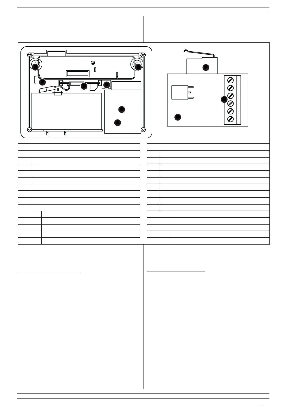
1.4 IDENTIFICAZIONE DELLE PARTI E DEI MORSETTI........................... 3
2. INSTALLAZIONE............................................................................................... 3
3. MANUTENZIONE E VERIFICHE PERIODICHE ............................................... 4
4. SMALTIMENTO E ROTTAMAZIONE................................................................ 4
Le informazioni riportate in questo manuale sono state compilate con cura,
tuttavia l’azienda produttrice non può essere ritenuta responsabile per
eventuali errori e/o omissioni. L’azienda si riserva il diritto di apportare in ogni
momento, e senza preavviso, miglioramenti e/o modiche ai prodotti descritti
nel presente manuale. L’azienda pone particolare attenzione al rispetto
dell’ambiente. Tutti i prodotti ed i processi produttivi sono progettati con criteri
di eco-compatibilità.
Il presente articolo è stato prodotto in Italia.
L’azienda ha un sistema di gestione della qualità certicato secondo la
norma ISO 9001:2008 (n° 4796 - A)
L’azienda ha un sistema di gestione ambientale certicato secondo la
norma ISO 14001:2004 (n° 4796 - E)
L’azienda ha un sistema di gestione della salute e sicurezza sul lavoro
certicato secondo la norma ISO 45001:2018 (n° 4796 - I)
The informations in this manual have been issued with care, anyway the
manufacturer will not be responsible for any errors or omissions. The
manufacturer reserves the rights to improve or modify the products described
in this manual at any times and without advance notice. The manufacturer
pays particular attention to environment respect. Each product and each
process have been designed with eco-compatibility criteria.
This product has been made in Italy.
The company has a certied system of quality management according
to ISO 9001:2008 (n° 4796 - A) standard.
The company has a certied system of environmental management
according to ISO 9001:2004 (n° 4796 - E) standard.
The company has a certied system of health and work security
management according to ISO 45001:2018 (n° 4796 - I) standard.
1. DESCRIPTION .................................................................................................. 2
1.1 TECHNICAL FEATURES ....................................................................... 2
1.2 PACKAGING CONTENTS...................................................................... 2
1.4 PARTS AND TERMINAL BLOCK IDENTIFICATION.............................. 3
2. INSTALLAZIONE............................................................................................... 3
3. MAINTENANCE AND PERIODIC CHECKS ..................................................... 4
4. DISPOSAL AND SCRAPPING.......................................................................... 4
- Translation of the original instructions (original instructions in Italian) -
CONTENTS
1. DESCRIPTION
The UPS has been developed to guarantee the autonomy of the
cameras in case of absence of the power supply for non-PoE
cameras.
Inside it allows a 12 V and 1.3 Ah battery to be housed, thus
guaranteeing, for example, an autonomy of 5 hours for a camera
with 210 mA of consumption and IR LEDs on.
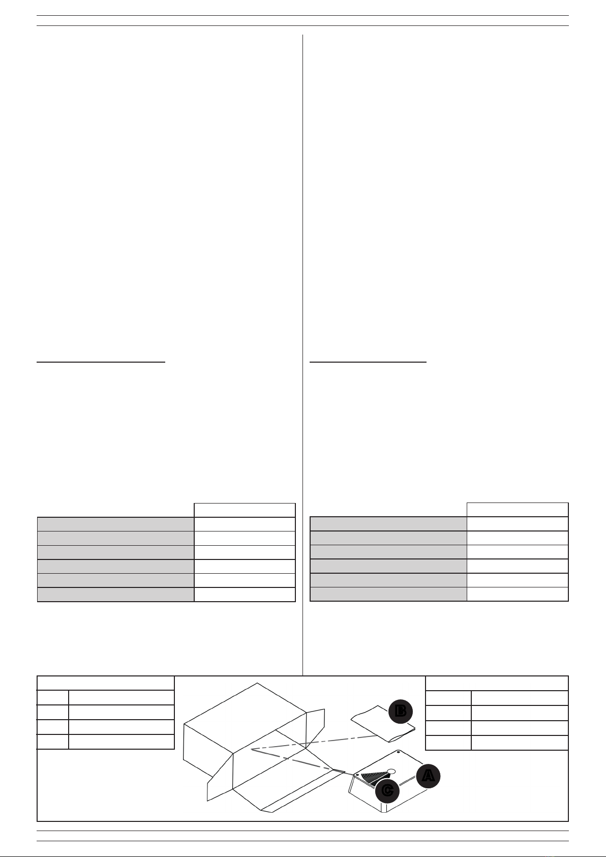
1.2 CONTENUTO DELLA CONFEZIONE
Tabella 2
Part. Identicazione
AGruppo di continuità
BIstruzioni
CCavo di collegamento
B
1.2 PACKAGING CONTENTS
Table 2
Ref. Identication
AUPS
BInstructions
CLinking cable
A
1.1 TECHNICAL FEATURES
Table 1
Power supply 12 V
Compatible battery (item 473LI1,3-12) 12 V 1,3 Ah
Working temperature 5 ÷ 40 °C
Dimensions 185 x 135 x 60 mm
Materials self-extinguishing ABS
Boc weight without battery 350 g
C


 Plus Startup manual")


