2
LINCE ITALIA S.p.A.
- Istruzioni originali -
1. INTRODUZIONE
Ilgruppodicontinuitàèstatosviluppatopergarantirelal'autonomia
delle videocamere in caso di assenza dell'alimentazione di rete.
Al suo interno permette di alloggiare una batteria da 12 V e 1,2
Ah garantendo quindi, ad esempio un'autonomia di 5 ore ad una
telecamera con 210 mA di consumo.
INDICE
1. INTRODUZIONE................................................................................................ 2
1.1 CARATTERISTICHE TECNICHE........................................................... 2
1.2 CONTENUTO DELLA CONFEZIONE .................................................... 3
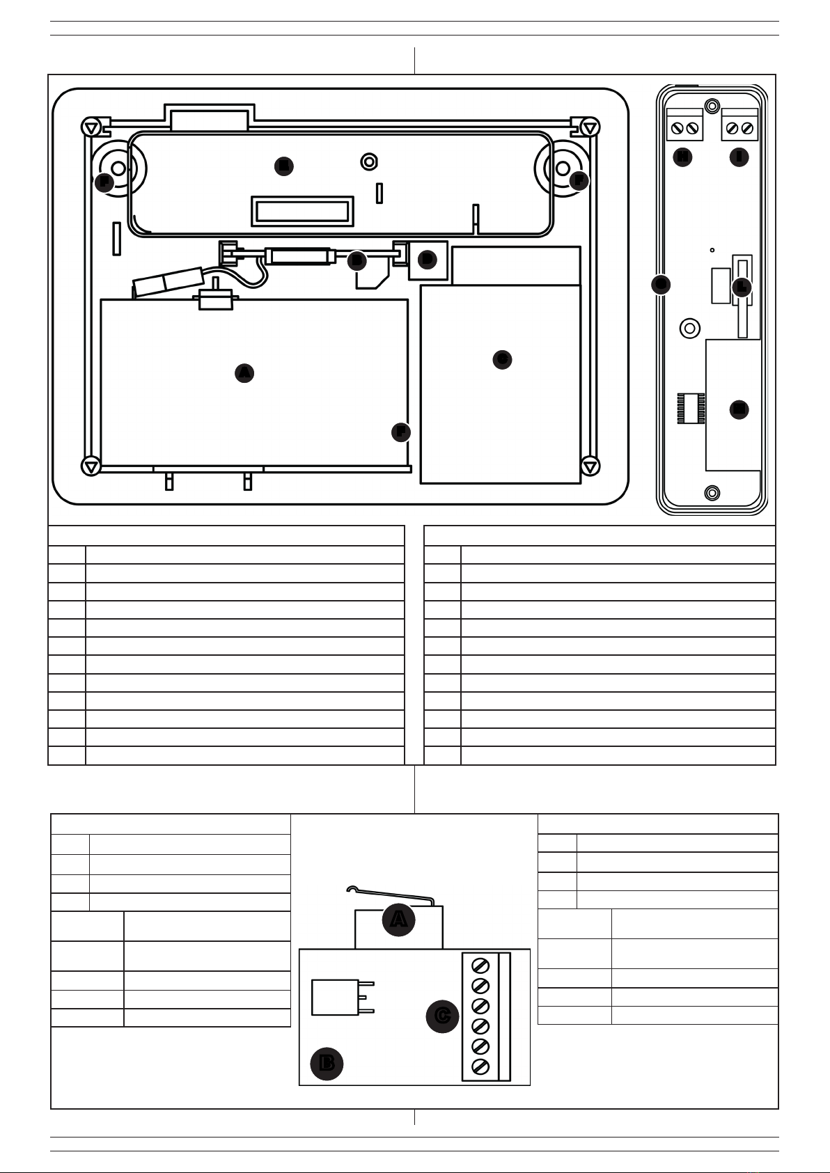
1.3 IDENTIFICAZIONE DELLE PARTI ........................................................ 3
1.4 IDENTIFICAZIONE DELLE PARTI INTERNE ........................................ 4
1.5 IDENTIFICAZIONE DELLA SCHEDA E DEI MORSETTI ...................... 4
2. VERIFICA PORTATA......................................................................................... 5
3. INSTALLAZIONE............................................................................................... 5
3.1 CONNESSIONE VIDEOVERIFICA ........................................................ 5
4. MEMORIZZAZIONE .......................................................................................... 6
4.1 FUNZIONE SLEEP................................................................................. 6
5. MANUTENZIONE E VERIFICHE PERIODICHE ............................................... 6
6. SMALTIMENTO E ROTTAMAZIONE................................................................ 6
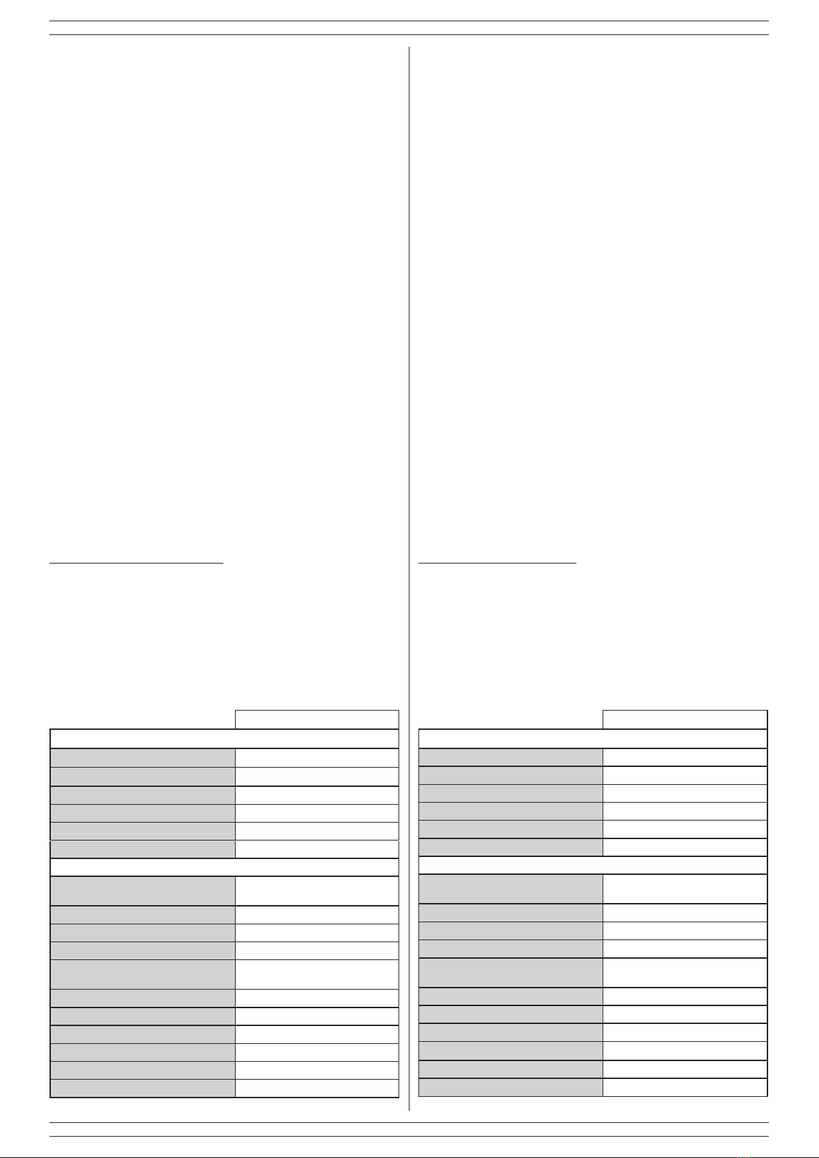
1.1 CARATTERISTICHE TECNICHE
Tabella 1
MODULO UPS
Alimentazione 12 V
Batteria compatibile (art. 473LI1,3-12) 12 V 1,3 Ah
Temperatura di esercizio 5 ÷ 40 °C
Dimensioni 185 x 135 x 60 mm
Materiale ABS autoestinguente
Peso della confezione senza batteria 350 g
MODULO USCITA RADIO INTEGRATO
Alimentazione Batteria al litio AA (LiSOCl2) 3,6 V
2200 mAh (inclusa)
Consumo 12 μA
Carico massimo pilotato dall'uscita 12 Vcc @ 1 A
Caratteristiche ingresso Ingresso NC riferito a massa
Frequenze di trasmissione 869,40 MHz-869,65 MHz 1 canale,
868,00 MHz-868,60 MHz 4 canali
FH Frequency Hopping
TDMA Time Division Multiple Access
AES Advanced Encryption Standard
Portata no a 1500 m in aria libera
Protezione contro lo strappo microswitch
Immunità alla radiofrequenza EN50130-4
1. INTRODUCTION ................................................................................................ 2
1.1 TECHNICAL FEATURES ........................................................................ 2
1.2 PACKAGING CONTENTS....................................................................... 3
1.3 PARTS IDENTIFICATION........................................................................ 3
1.4 INTERNAL PARTS IDENTIFICATION..................................................... 4
1.5 BOARD AND TERMINAL BLOCK IDENTIFICATION.............................. 4
2. WIRELESS RANGE CHECK ............................................................................ 5
3. INSTALLATION ................................................................................................. 6
3.1 VIDEOVERIFICATION CONNECTION ................................................... 5
4. PAIRING ............................................................................................................ 6
4.1 SLEEP FUNCTION ................................................................................. 6
5. MAINTENANCE AND PERIODIC CHECKS ...................................................... 6
6. DISPOSAL AND SCRAPPING........................................................................... 6
Le informazioni riportate in questo manuale sono state compilate con
cura, tuttavia LINCE ITALIA S.p.A. non può essere ritenuta responsabile
per eventuali errori e/o omissioni. LINCE ITALIA S.p.A. si riserva il diritto
di apportare in ogni momento e senza preavviso, miglioramenti e/o
modiche ai prodotti descritti nel presente manuale. Consultare il sito
www.lince.net per le condizioni di assistenza e garanzia. LINCE ITALIA
S.p.A. pone particolare attenzione al rispetto dell’ambiente. Tutti i prodotti
ed i processi produttivi sono progettati con criteri di eco-compatibilità.
Il presente articolo è stato prodotto in Italia.
• L’azienda ha un sistema di gestione della qualità certicato
secondo la norma ISO 9001:2008 (n° 4796 - A)
• L’azienda ha un sistema di gestione ambientale certicato
secondo la norma ISO 14001:2004 (n° 4796 - E)
• L’azienda ha un sistema di gestione della salute e sicurezza sul
lavorocerticatosecondolanormaISO45001:2018(n°4796-I)
The information in this manual has been issued with care, but LINCE
ITALIA S.p.A. will not be responsible for any errors or omissions. LINCE
ITALIA S.p.A. reserves the right to improve or modify the products
described in this manual at any time and without advance notice.Terms
and conditions regarding assistance and the product warranty can be
found at LINCE ITALIA’s website www.lince.net. LINCE ITALIA S.p.A.
makes it a priority to respect the environment. All products and production
processes are designed to be eco-friendly and sustainable.
This product has been Made in Italy.
• The company has a certied system of quality management
according to ISO 9001:2008 (n° 4796 - A) standard.
• The company has a certied system of environmental
management according to ISO 9001:2004 (n° 4796 - E) standard.
• The company has a certied system of health and work
securitymanagementaccordingtoISO45001:2018(n°4796-I)
standard.
-Translationoftheoriginalinstructions(originalinstructionsinItalian)-
CONTENTS
1. DESCRIPTION
The UPS has been developed to guarantee the autonomy of the
cameras in case of absence of the power supply. Inside it allows
a 12 V and 1.3 Ah battery to be housed, thus guaranteeing, for
example, an autonomy of 5 hours for a camera with 210 mA of
consumption.
1.1 TECHNICAL FEATURES
Table 1
UPS MODULE
Power supply 12 V
Compatible battery (item 473LI1,3-12) 12 V 1,3 Ah
Working temperature 5 ÷ 40 °C
Dimensions 185 x 135 x 60 mm
Materials self-extinguishing ABS
Box weight without battery 350 g
WIRELESS BUILT-IN MODULE
Operating voltage Lithium battery AA (LiSOCl2) 3,6 V
2200 mAh (included)
Power consumotion 12 μA
Maximum load driven by the output 12 Vdc @ 1 A
Input features NC input referred to ground
Operating frequency 869,40 MHz-869,65 MHz 1 canale,
868,00 MHz-868,60 MHz 4 canali
FH Frequency Hopping
TDMA Time Division Multiple Access
AES Advanced Encryption Standard
Wireless range up to 1500 m in free air
Protection against wall removal microswitch
Radiofrequency immunity EN50130-4


 Plus Startup manual")


