manuals.online logo
Brands
  1. Home
  2. •
  3. Brands
  4. •
  5. Lincoln Electric
  6. •
  7. Sander
  8. •
  9. Lincoln Electric Torchmate 4 00 Series User manual

Lincoln Electric Torchmate 4 00 Series User manual

21
Replacing the 4x00 X-Axis Motor Belt
DOC #:7301-0-US70-111318-AM-01-02
support@torchmate.com
Replacing the 4x00 X-Axis Motor Belt
Intro: Over me, the ming belts on the 4400 and 4800 machines that join the
motor and pinion gear pulleys will wear out and require replacements. The
instrucons below explain the procedure for replacing the belts.
Tools:  1/8 Allen Wrench
 3/16 Allen Wrench
 9/64 Allen Wrench
 5/64 Allen Wrench
 1/4 Allen Wrench
 (1) Zip Tie
Warning: BEFORE BEGINNING, PLEASE POWER OFF ALL EQUIPMENT INCLUDING THE
ACCUMOVE CONTROLLER!*
*Irreparable damage will occur to the controller and will not be covered
under warranty if the equipment is not turned o.
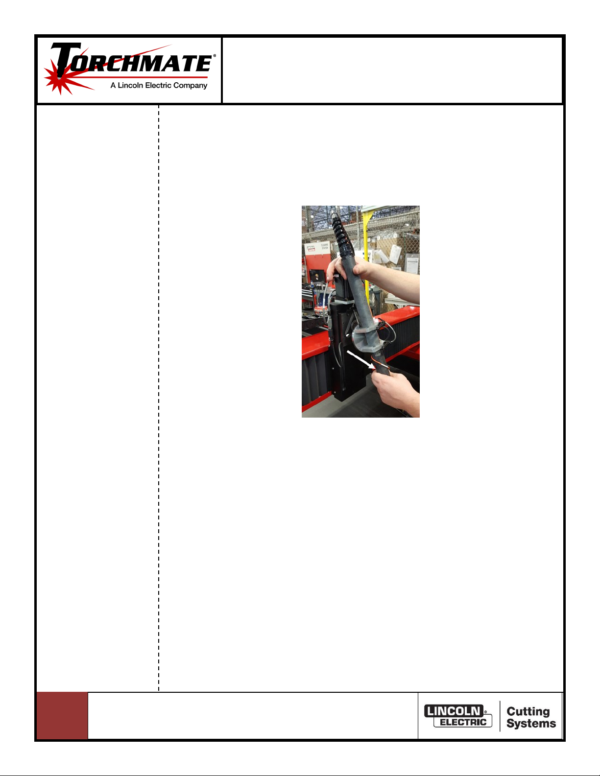
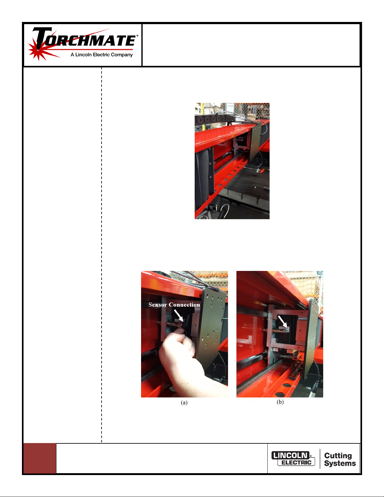
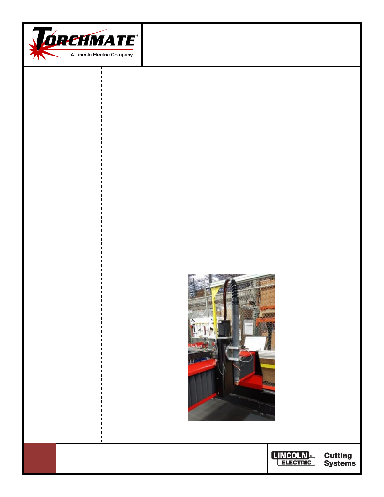
Part 1: Removing the plasma torch shown in Fig. 1.
Fig. 1: Plasma torch.
22
Replacing the 4x00 X-Axis Motor Belt
DOC #:7301-0-US70-111318-AM-01-02
support@torchmate.com
Replacing the 4x00 X-Axis Motor Belt
Step 1: Being careful to avoid the pinch point at the magnet, gently hold and pull
the torch in the direcon shown in Fig. 2 to dismount the torch holder puck
from the magnec breakaway base. Slide the braided metal cable o of the
catch tab to move the torch away from Z-axis lier.
Fig. 2: Gently pull in the direcon shown to dismount the plasma torch.
23
Replacing the 4x00 X-Axis Motor Belt
DOC #:7301-0-US70-111318-AM-01-02
support@torchmate.com
Replacing the 4x00 X-Axis Motor Belt
Part 2: Removing the Z-axis lier shown in Fig. 3.
Step 1: Remove the 4-pin molex on the right side of the Z-axis lier as shown in Fig.
4 by pressing down on the switch release and pulling the two ends apart.
Fig. 4: Removing the 4-pin molex.
24
Replacing the 4x00 X-Axis Motor Belt
DOC #:7301-0-US70-111318-AM-01-02
support@torchmate.com
Replacing the 4x00 X-Axis Motor Belt
Step 2: Unscrew and remove the cable clip on the le side of the Z-axis lier as
shown in Fig. 5.
Fig. 5: Removing the cable clip.
Step 3: Disconnect the Z-axis motor cable as shown in Fig. 6a & b. Try to avoid
pulling from the cable so none of the wires pull out of the cable plug.
Fig. 6: Disconnecng the power supply from the motor.
25
Replacing the 4x00 X-Axis Motor Belt
DOC #:7301-0-US70-111318-AM-01-02
support@torchmate.com
Replacing the 4x00 X-Axis Motor Belt
Step 4: Disconnect the breakaway cable (3 pin DIN) cable on the le side of the Z-
axis lier as shown in Fig. 7a & b.
Fig. 7: Disconnecng the breakaway cable (3 pin DIN) on the le side of the
Z-axis lier.
Step 5: Cut the zip e as shown in Fig. 8a and disconnect the motor cable by
pressing down on the release switch and pulling apart as shown in Fig. 8b.
Fig. 8: (a) Cung the zip e & (b) disconnecng the motor cable.
26
Replacing the 4x00 X-Axis Motor Belt
DOC #:7301-0-US70-111318-AM-01-02
support@torchmate.com
Replacing the 4x00 X-Axis Motor Belt
Step 6: Remove the four screws from the torch mount as shown in Fig. 9a with a
1/4 Allen Wrench and dismount the torch mount as shown in Fig. 9b.
Fig. 9: Remove the screws on each inside corner of the plasma torch mount.
27
Replacing the 4x00 X-Axis Motor Belt
DOC #:7301-0-US70-111318-AM-01-02
support@torchmate.com
Replacing the 4x00 X-Axis Motor Belt
Part 3: Removing the tool plate and gantry motor as shown in Fig. 10.
Step 1: Remove each of the three screws on the le and right sides of the tool plate
holding the bellows as shown in Fig. 11a-c.
Fig. 11: Removing each of the three screws on the le and right sides of
the tool plate holding the bellows.
Fig. 10: Tool plate.
28
Replacing the 4x00 X-Axis Motor Belt
DOC #:7301-0-US70-111318-AM-01-02
support@torchmate.com
Replacing the 4x00 X-Axis Motor Belt
Step 2: Pull back the bellows to expose the inside of the gantry as shown in Fig. 12.
Fig. 12: Exposed gantry.
Step 3: Disconnect the sensor connecon as shown in Fig. 13a & b and remove it
from the gantry by pulling it out from the right side of the tool plate.
Fig. 13: Disconnecng the sensor connecon.
29
Replacing the 4x00 X-Axis Motor Belt
DOC #:7301-0-US70-111318-AM-01-02
support@torchmate.com
Replacing the 4x00 X-Axis Motor Belt
Step 4: Unscrew each of the four screws on the tool plate as shown in Fig. 14a and
remove it by pulling it up and o to the side as shown in Fig. 14b.
Fig. 14: (a) Four screws to be removed and (b) Removing the tool plate.
Step 5: Remove each of the two screws from the tool plate stando as shown in
Fig. 15a and remove the tool plate stando as shown in Fig. 15b.
Fig. 15. Removing each of the two screws from the tool plate stando.
210
Replacing the 4x00 X-Axis Motor Belt
DOC #:7301-0-US70-111318-AM-01-02
support@torchmate.com
Replacing the 4x00 X-Axis Motor Belt
Step 6: Remove the two shoulder bolts as shown in Fig. 16a & b to remove the mo-
tor. Please note that only the boom shoulder bolt has a spring.
Fig. 16: Removing the gantry motor from the gantry.
211
Replacing the 4x00 X-Axis Motor Belt
DOC #:7301-0-US70-111318-AM-01-02
support@torchmate.com
Replacing the 4x00 X-Axis Motor Belt
Part 4: Removing the Gantry Motor Belt.
Step 1: Loosen the four motor screws with a 9/64 Allen Wrench in each of the cor-
ners as shown below in Fig. 17, making sure to not fully remove them from
the plate.
Fig. 17: Loosening the four screws.
Step 2: Loosen the set screw with a 5/64 Allen Wrench as shown in Fig. 18 making
sure to not fully remove it from the plate. The motor should be able to slide
so the belt tension is relieved
Fig. 18: Loosening the set screw.
212
Replacing the 4x00 X-Axis Motor Belt
DOC #:7301-0-US70-111318-AM-01-02
support@torchmate.com
Replacing the 4x00 X-Axis Motor Belt
Step 3: Remove the four screws shown in Fig. 19 with a 9/64 Allen Wrench .
Fig. 19: Remove the four screws shown.
Step 4: Remove the four aluminum bushings shown in Fig. 20.
Fig. 20: Removing aluminum bushings.
213
Replacing the 4x00 X-Axis Motor Belt
DOC #:7301-0-US70-111318-AM-01-02
support@torchmate.com
Replacing the 4x00 X-Axis Motor Belt
Step 5: Push up on the belt from the large pulley to release it from the small pulley.
Remove the belt from the motor assembly as shown in Fig. 21.
Fig. 21: Removing the belt.
214
Replacing the 4x00 X-Axis Motor Belt
DOC #:7301-0-US70-111318-AM-01-02
support@torchmate.com
Replacing the 4x00 X-Axis Motor Belt
Step 1: Place the belt as shown in Fig. 17.
Fig. 17: Placing the belt.
Step 2: Place a poron of the belt onto the large pulley. Then spin the top gear in
the direcon shown to ensure the teeth from the belt “catch” onto the
gear.
Fig. 18: Posioning the belt.
Part 5: Installing & Adjusng the New Motor Belt
215
Replacing the 4x00 X-Axis Motor Belt
DOC #:7301-0-US70-111318-AM-01-02
support@torchmate.com
Replacing the 4x00 X-Axis Motor Belt
Step 3: Place the aluminum bushings as shown and ghten the four screws with a
9/64 Allen Wrench as shown in Fig. 19.
Fig. 19: Reinstalling the aluminum bushings.
Step 4: Tighten the set screw with a 5/64 Allen Wrench as shown in Fig. 20 in small
increments (1/8 to 1/4 of a turn at a me). Squeeze the belt with approxi-
mately 1 pound of force to make sure that the belt is not too loose or too
ght. When squeezing the belt from both sides, there should be a maximum
deecon between 1/16 to 1/8 of an inch. The arrows indicate how the belt
should be squeezed to determine proper tension.
Fig. 20: Seng the proper tension on the belt.
216
Replacing the 4x00 X-Axis Motor Belt
DOC #:7301-0-US70-111318-AM-01-02
support@torchmate.com
Replacing the 4x00 X-Axis Motor Belt
Step 5: Once the proper tension has been achieved, ghten the four screws as
shown in Fig. 21 with a 9/64 Allen Wrench to secure the motor into
posion.
Fig. 21: Tightening the four screws.
217
Replacing the 4x00 X-Axis Motor Belt
DOC #:7301-0-US70-111318-AM-01-02
support@torchmate.com
Replacing the 4x00 X-Axis Motor Belt
Step 1: Align the gantry motor as shown in Fig. 22 and secure each of the shoulder
bolts on the aluminum mounng plate with a 3/16 Allen Wrench, making
sure the short bolt is on the top side and the long bolt is on the boom.
Note only the boom shoulder bolt has a spring.
Part 6: Reinstallaon of the Gantry Motor
Fig. 22: Remounng the gantry motor.
Step 2: Secure the tool plate stando as shown in Fig. 23 using the two screws
shown.
Fig. 23: Remounng tool plate stando.
218
Replacing the 4x00 X-Axis Motor Belt
DOC #:7301-0-US70-111318-AM-01-02
support@torchmate.com
Replacing the 4x00 X-Axis Motor Belt
Step 3: Align the tool plate as shown in Fig. 24a and fasten it to the aluminum
brackets using the four screw slots shown.
Fig. 24: Installing the tool plate.
Step 4: Feed the sensor cable through the back slot and connect it to the sensor as
shown in Fig. 25a-d.
Fig. 25: Reconnecng the sensor.
219
Replacing the 4x00 X-Axis Motor Belt
DOC #:7301-0-US70-111318-AM-01-02
support@torchmate.com
Replacing the 4x00 X-Axis Motor Belt
Step 5: Re-secure the le bellow using the three screw slots on the le side of the
tool plate as shown in Fig. 26a-c.
Fig. 26: Re-securing the le bellow.
Step 6: Connect the gantry motor cable as shown in Fig. 27. Make sure the release
switch snaps into posion so that the two ends are locked into posion.
Fig. 27: Connecng the gantry motor cable.
220
Replacing the 4x00 X-Axis Motor Belt
DOC #:7301-0-US70-111318-AM-01-02
support@torchmate.com
Replacing the 4x00 X-Axis Motor Belt
Step 7: On the right side of the tool mount, align the sensor (top) and motor
(boom) cables in the grooves as shown in Fig. 28.
Fig. 28: Aligning the sensor (top) and motor (motor) cables.
Step 8: While ensuring that the two previous cables are in their grooves, slide the
right bellow and align the three holes and reinsert the three screws as
shown in Fig. 29.
Fig. 29: Reinstalling the right bellow.

This manual suits for next models

2

Popular Sander manuals by other brands

Eastwood PRO MINI ANGLE instructions

Eastwood

Eastwood PRO MINI ANGLE instructions

Wilton 4002 Operating instructions & parts manual

Wilton

Wilton 4002 Operating instructions & parts manual

Triton TA 1200BS Operating and safety instructions

Triton

Triton TA 1200BS Operating and safety instructions

Makita GV5010 instruction manual

Makita

Makita GV5010 instruction manual

Bosch GSS 23 AE Original instructions

Bosch

Bosch GSS 23 AE Original instructions

Draper PT135 instructions

Draper

Draper PT135 instructions

Makita BO4552 parts manual

Makita

Makita BO4552 parts manual

Thomashilfen EASyS Advantage Assembly instructions-Accessory

Thomashilfen

Thomashilfen EASyS Advantage Assembly instructions-Accessory

RODEX RDX374 instruction manual

RODEX

RODEX RDX374 instruction manual

Superabrasive LAVINA 20N-S user manual

Superabrasive

Superabrasive LAVINA 20N-S user manual

Hitachi Koki FSV 10SA Handling instructions

Hitachi Koki

Hitachi Koki FSV 10SA Handling instructions

Makita SA7000C instruction manual

Makita

Makita SA7000C instruction manual

Skil 7380 Original instructions

Skil

Skil 7380 Original instructions

Baileigh DBG-62 Operator's manual

Baileigh

Baileigh DBG-62 Operator's manual

Cissell PANTOP24VMAN594 owner's manual

Cissell

Cissell PANTOP24VMAN594 owner's manual

Baileigh Industrial ES-9138 Operator's manual

Baileigh Industrial

Baileigh Industrial ES-9138 Operator's manual

Jet J-4002 Operating instructions and parts manual

Jet

Jet J-4002 Operating instructions and parts manual

NSI Solutions Seam Phantom SP-A2 instruction manual

NSI Solutions

NSI Solutions Seam Phantom SP-A2 instruction manual

manuals.online logo
manuals.online logoBrands
  • About & Mission
  • Contact us
  • Privacy Policy
  • Terms and Conditions

Copyright 2025 Manuals.Online. All Rights Reserved.