Lincoln Electric INVERTEC V270 User manual

W83CE285
02/2002
Rev.0
INVERTECV270
OPERATOR’S MANUAL
MANUALE OPERATIVO
LINCOLN ELECTRIC ITALIA S.r.l
Via degli Artigiani 80, 17015 Celle Ligure (SV), Italia
www.lincolnelectric.com

2
Declaration of conformity
Dichiarazione di conformità
Konformitätserklärung
Declaración de conformidad
Déclaration de conformité
Samsvars erklæring
Verklaring van overeenstemming
Försäkran om överensstämmelse
LINCOLN ELECTRIC ITALIA S.r.l.
Declares that the welding machine:
Dichiara che Il generatore per saldatura tipo:
Erklärt, daß die Bauart der Maschine:
Declara que el equipo de soldadura:
Déclare que le poste de soudage:
Bekrefter at denne sveisemaskin:
Verklaart dat de volgende lasmachine:
Försäkrar att svetsomriktaren:
INVERTECV270 s/n
conforms to the following directives:
è conforme alle seguenti direttive:
den folgenden Bestimmungen entspricht:
es conforme con las siguientes directivas:
Est conforme aux directives suivantes:
er i samsvar med følgende direktiver:
Overeenkomt conform de volgende richtlijnen:
överensstämmer med följande direktiv:
73/23/CEE, 93/68/CEE, 89/336/CEE, 92/31/CEE
and has been designed in conformance with the following norms:
ed è stato progettato in conformità alle seguenti norme:
und in Übereinstimmung mit den nachstehenden Normen hergestellt wurde:
y ha sido diseñado de acuerdo con las siguientes normas:
et qu'il a été conçu en conformité avec les normes:
og er produsert og testet iht. følgende standarder:
en is ontworpen conform de volgende normen:
och att den konstruerats i överensstämmelse med följande standarder:
EN 50199, EN 60974-1
LINCOLN ELECTRIC ITALIA S.r.l., Via degli Artigiani 80, 17015 Celle Ligure (SV), Italia

3
ENGLISH INDEX
Safety ..............................................................................................................................................................................4
Installation and Operator Instructions..............................................................................................................................5
Electromagnetic Compatibility (EMC) ............................................................................................................................10
INVERTEC V270 Technical Specifications....................................................................................................................10
INDICE ITALIANO
Sicurezza.......................................................................................................................................................................11
Installazione e Istruzioni Operative................................................................................................................................12
Compatibilità Elettromagnetica (EMC)...........................................................................................................................17
INVERTEC V270 Specifiche Tecniche..........................................................................................................................17
Spare Parts, Parti di Ricambio, Ersatzteile, Lista de Piezas de Recambio, Pièces de Rechange, Deleliste, Reserve
Onderdelen, Reservdelar...............................................................................................................................................18
Accessories, Accessori, Zubehör, Accesorios, Accessoires, Tilleggsutstyr, Accessores, Tillbehör...............................20

4
Safety
WARNING
This equipment must be used by qualified personnel. Be sure that all installation, operation, maintenance and repair
procedures are performed only by qualified individuals. Read and understand this manual before operating this
equipment. Failure to follow the instructions in this manual could cause serious personal injury, loss of life, or damage to
this equipment. Read and understand the following explanations of the warning symbols. Lincoln Electric is not
responsible for damages caused by improper installation, improper care or abnormal operation.
WARNING: This symbol indicates that instructions must be followed to avoid serious personal injury,
loss of life, or damage to this equipment. Protect yourself and others from possible serious injury or
death.
READ AND UNDERSTAND INSTRUCTIONS: Read and understand this manual before operating
this equipment. Arc welding can be hazardous. Failure to follow the instructions in this manual could
cause serious personal injury, loss of life, or damage to this equipment.
ELECTRIC SHOCK CAN KILL: Welding equipment generates high voltages. Do not touch the
electrode, work clamp, or connected work pieces when this equipment is on. Insulate yourself from
the electrode, work clamp, and connected work pieces.
FUMES AND GASES CAN BE DANGEROUS: Welding may produce fumes and gases hazardous to
health. Avoid breathing these fumes and gases. To avoid these dangers the operator must use
enough ventilation or exhaust to keep fumes and gases away from the breathing zone.
ARC RAYS CAN BURN: Use a shield with the proper filter and cover plates to protect your eyes from
sparks and the rays of the arc when welding or observing. Use suitable clothing made from durable
flame-resistant material to protect you skin and that of your helpers. Protect other nearby personnel
with suitable, non-flammable screening and warn them not to watch the arc nor expose themselves to
the arc.
WELDING SPARKS CAN CAUSE FIRE OR EXPLOSION: Remove fire hazards from the welding
area and have a fire extinguisher readily available. Welding sparks and hot materials from the welding
process can easily go through small cracks and openings to adjacent areas. Do not weld on any
tanks, drums, containers, or material until the proper steps have been taken to insure that no
flammable or toxic vapors will be present. Never operate this equipment when flammable gases,
vapors or liquid combustibles are present.
ELECTRICALLY POWERED EQUIPMENT: Turn off input power using the disconnect switch at the
fuse box before working on this equipment. Ground this equipment in accordance with local electrical
regulations.
ELECTRICALLY POWERED EQUIPMENT: Regularly inspect the input, electrode, and work clamp
cables. If any insulation damage exists replace the cable immediately. Do not place the electrode
holder directly on the welding table or any other surface in contact with the work clamp to avoid the
risk of accidental arc ignition.
ELECTRIC AND MAGNETIC FIELDS MAY BE DANGEROUS: Electric current flowing through any
conductor creates electric and magnetic fields (EMF). EMF fields may interfere with some
pacemakers, and welders having a pacemaker should consult their physician before operating this
equipment.
CYLINDER MAY EXPLODE IF DAMAGED: Use only compressed gas cylinders containing the
correct shielding gas for the process used and properly operating regulators designed for the gas and
pressure used. Always keep cylinders in an upright position securely chained to a fixed support. Do
not move or transport gas cylinders with the protection cap removed. Do not allow the electrode,
electrode holder, work clamp or any other electrically live part to touch a gas cylinder. Gas cylinders
must be located away from areas where they may be subjected to physical damage or the welding
process including sparks and heat sources.
WELDED MATERIALS CAN BURN: Welding generates a large amount of heat. Hot surfaces and
materials in work area can cause serious burns. Use gloves and pliers when touching or moving
materials in the work area.
HF CAUTION: The high frequency used for contact-free ignition with TIG (GTAW) welding, can interfere
with the operation of insufficiently shielded computer equipment, EDP centers and industrial robots,
even causing complete system breakdown. TIG (GTAW) welding may interfere with electronic
telephone networks and with radio and TV reception.

5
CE COMPLIANCE: This equipment complies to the European Communities directives.
SAFETY MARK: This equipment is suitable for supplying power for welding operations carried out in
an environment with increased hazard of electric shock.
Installation and Operator Instructions
Read this entire section before installation or operation
of the machine.
Location and Environment
This machine will operate in harsh environments.
However, it is important that simple preventative
measures are followed to assure long life and reliable
operation.
•Do not place or operate this machine on a surface
with an incline greater than 15° from horizontal.
•This machine must be located where there is free
circulation of clean air without restrictions for air
movement to and from the air vents. Do not cover
the machine with paper, cloth or rags when
switched on.
•Dirt and dust that can be drawn into the machine
should be kept to a minimum.
•This machine has a protection rating of IP23S.
Keep it dry when possible and do not place it on wet
ground or in puddles.
•Locate the machine away from radio controlled
machinery. Normal operation may adversely affect
the operation of nearby radio controlled machinery,
which may result in injury or equipment damage.
Read the section on electromagnetic compatibility in
this manual.
•Do not operate in areas with an ambient
temperature greater than 40°C.
Input Supply Connection
Check the input voltage, phase, and frequency supplied
to this machine before turning it on. The allowable input
voltage is indicated in the technical specification section
of this manual and on the rating plate of the machine.
Verify the connection of grounding wires from the
machine to the input source.
Make sure the amount of power available from the input
connection is adequate for normal operation of the
machine. The necessary fuse and cable sizes are
indicated in the technical specification section of this
manual.
This machine is designed to operate on engine driven
generators as long as the 400Vac auxiliary can supply
adequate power as indicated in the technical
specification section of this manual. The auxiliary supply
of the generator must also meet the following conditions.
•The AC waveform peak voltage is below 720V.
•The AC waveform frequency is between 50 and 60
hertz.
•The RMS voltage of the AC waveform is always
equal to 400Vac ± 15%.
It is important to check these conditions because many
engine driven generators produce high voltage spikes.
Operation of this machine on engine driven generators
not conforming to these conditions is not recommended
and may damage the machine.
Output Connections
A quick disconnect system
using Twist-MateTM cable
plugs is used for the welding
cable connections. Refer to
the following sections for more
information on connecting the
machine for operation of stick
welding (MMA) or TIG welding
(GTAW).
Stick Welding (MMA)
First determine the proper
electrode polarity for the
electrode to be used. Consult
the electrode data for this
information. Then connect the
output cables to the output terminals of the machine for
the selected polarity. For example, if DC(+) welding will
be used then connect the electrode cable to the (+)
terminal of the machine and the work clamp to the (-)
terminal. Insert the connector with the key lining up with
the keyway and rotate approximately ¼ turn clockwise.
Do not over tighten.
For DC(-) welding switch the cable connections at the
machine so that the electrode cable is connected to (-)
and the work clamp is connected to (+).
TIG Welding (GTAW)
This machine does not include a TIG torch necessary for
TIG welding, but one may be purchased separately.
Refer to the accessories section for more information.
Most TIG welding is done with DC(-) polarity; connect
the torch cable to the (-) terminal of the machine and the
work clamp to the (+) terminal. Insert the connector with
the key lining up with the keyway and rotate
approximately ¼ turn clockwise. Do not over tighten.
For V270-S machines, connect the gas hose from the
TIG torch to a gas regulator on the cylinder of gas to be
used.

6
For V270-T machines,
connect the gas hose
from the TIG torch to the
gas connector (B) on the
front of the machine. If
necessary, an extra gas
connector for the fitting on
the front of the machine is
included in the package.
Next, connect the fitting on the back of the machine to a
gas regulator on the cylinder of gas to be used. An input
gas line and the required fittings are also included in the
package. Connect the TIG torch trigger to the trigger
connector (A) on the front of the machine.
Remote Control Connection
Refer to the accessories section for a list of remote
controls. If a remote control is used, it will be connected
to the remote connector (C) on the front of the machine.
The machine will automatically detect the remote control,
turn on the REMOTE LED, and switch to remote control
mode. More information on this mode of operation will
be given in the next section.
Controls and Operational Features
A. Power Switch: Controls
the input power to the
machine. Make sure the
machine is properly
connected to the input
supply before turning the
machine on.
B. Fan: The cooling fan will
turn ON when the machine
is turned ON and it will
continue to run whenever
the output of the machine
is ON. If the output of the
machine is OFF for more
than five minutes, the fan
will turn OFF. This
reduces the amount of dirt
that is deposited inside the machine and reduces
power consumption. Refer to the Output LED
section below for more information about conditions
when the output of the machine is ON.
If a Coolarc 20 is connected to a V270-T, it will be
turned ON and OFF with the operation of the fan.
When Stick welding mode is used the Coolarc 20
will be OFF.
C. Gas Inlet (V270-T only): Connector for the TIG
shielding gas. Use the supplied gas line and
connector to connect the machine to the gas
source. The gas source must have a pressure
regulator and flow gage installed.
D. Mode Switch: This switch changes the welding
modes of the machine. The V270-S has two
welding modes: Stick (SMAW) and Lift TIG (GTAW).
The V270-T machines have three welding modes:
Stick (SMAW), Lift TIG (GTAW) and HF TIG
(GTAW).
When the mode switch is in the Stick position, the
following welding features are enabled.
•Hot Start: This is a temporary increase in the
output current during the start of the stick
welding process. This helps ignite the arc
quickly and reliably. The amount of hot start
can be adjusted on the V270-S, refer to Hot
Start, described below.
•Arc Force: This is a temporary increase in the
output current during normal stick welding.
This temporary increase in output current is
used to clear intermittent connections between
the electrode and the weld puddle that occur
during normal stick welding. The amount of arc
force can be adjusted on the V270-S, refer to
Arc Force, described below.
•Anti-Sticking: This is a function which
decreases the output current of the machine to
a low level when the operator makes an error
and sticks the electrode to the work piece. This
decrease in current allows the operator to
remove the electrode from the electrode holder
without creating large sparks which can
damage the electrode holder.
When the mode switch is in the Lift TIG position, the
stick welding functions are disabled and the
machine is ready for Lift TIG welding. Lift TIG is a
method of starting a TIG weld by first pressing the
TIG torch electrode on the work piece in order to
create a low current short circuit. Then, the
electrode is lifted from the work piece to start the
TIG arc.
The last mode switch position, HF TIG, is only
available on the V270-T. When the mode switch is
in this position, the stick welding functions are
disabled and the machine is ready for HF TIG
welding. During the HF TIG mode, the TIG arc is
started by HF without pressing the electrode on the
work piece. The HF used for starting the TIG arc
will remain on for 6.5 seconds; if the arc is not
started in this time limit, the trigger sequence must
be restarted.

7
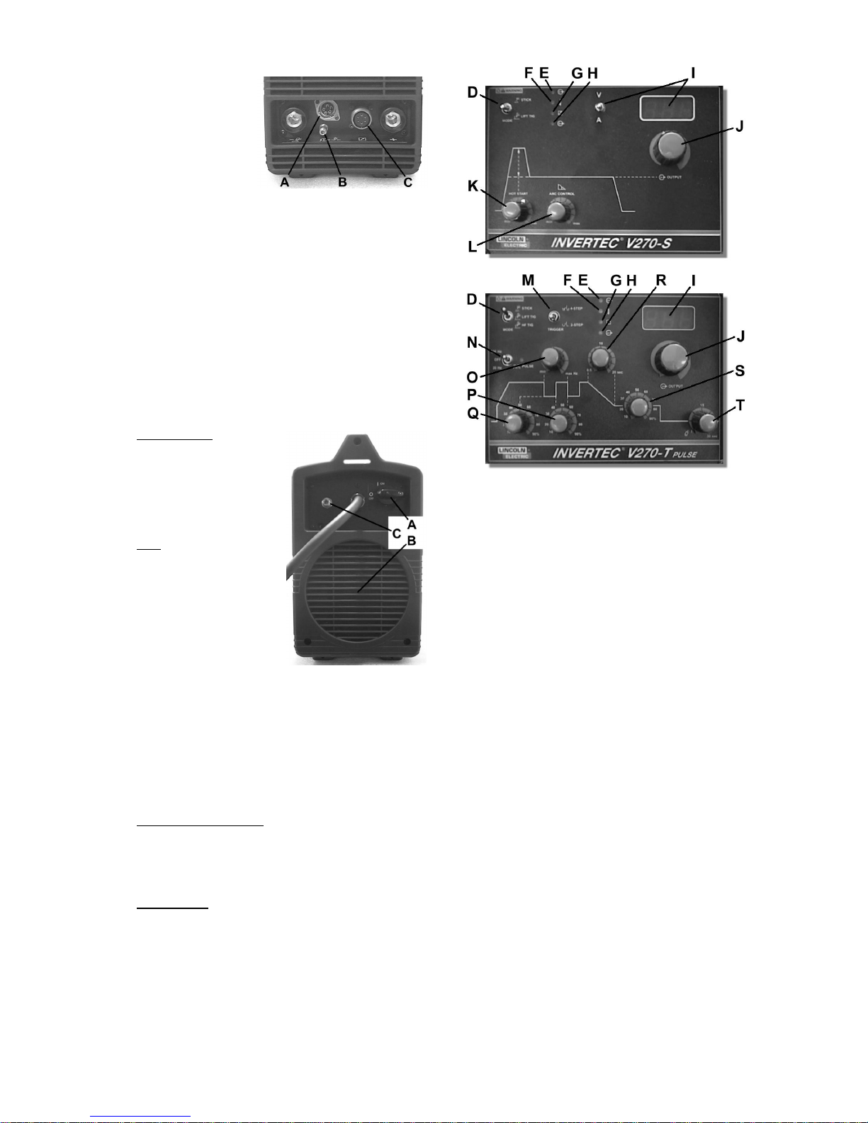
E. Power LED: This indicator will flash on and off
when the machine is first turned on. After
approximately 2 seconds it will stop flashing and
remain on to signal that the machine is ready.
F. Thermal LED: This indicator will turn on when the
machine is overheated and the output has been
disabled. This normally occurs when the duty cycle
of the machine has been exceeded. Leave the
machine on to allow the internal components to
cool. When the indicator turns off, normal operation
is again possible.
G. Remote LED [text removed]: This indicator will turn
on when a remote control is connected to the
machine via the remote control connector. Using a
remote control will change the function of the output
current control, refer to the output current control
section [text removed].
H. Output LED: This indicator turns on when the
output of the machine is on. Both the type of
machine and the position of the mode switch
determine when the output of the machine is turned
on.
V270-S: In the stick welding mode, the output of
the machine is automatically turned ON. However,
in the Lift TIG welding mode, the connection of a
remote control determines if the output is ON or
OFF. If a remote control is not connected (the
Remote LED is OFF) then the output of the machine
is automatically turned ON. If a remote control is
connected (the Remote LED is ON) then the output
of the machine is turned ON and OFF by the remote
connector on the front of the machine.
V270-T: In stick welding mode, the output of the
machine is automatically turned ON. However, in
both of the TIG welding modes, the output of the
machine is turned ON and OFF by the TIG torch
connected to the trigger connector on the front of
the machine.
I. Meter [text removed]: This meter displays the
preset welding current before welding and the actual
welding current during welding. Like the output
current control, the function of the meter is changed
if a remote control is connected. If the Remote LED
is ON, this indicates that a remote control is
connected and the meter will display the following
information before welding (during welding, the
meter always displays the actual welding current):
Stick Welding Mode: The meter displays the
preset welding current but this is adjusted from the
remote control as explained in the Output Current
Control section.
TIG Welding Modes: The meter displays the
maximum output current which is set by the output
current control knob. The preset welding current is
then adjusted by the remote control, but it is not
displayed on the meter.
V270-S: The V270-S has a Voltage / Current switch
to change the displayed value on the meter. If this
switch is set to voltage, the meter will always display
the output voltage of the machine.
J. Output Current Control: This controls the output, or
welding, current of the machine.
The function of this control knob is changed if a
remote control is connected. If the Remote LED is
ON, this indicates that a remote control is connected
and the function of the output current control will be:
Stick Welding Mode: The remote control will
adjust the output current of the machine from 5 to
270A. The output current control knob on the
display panel is not used.
TIG Welding Modes: The maximum output current
of the machine is set by the output current control
knob. Then the remote control adjusts the output
current from the minimum output (5A) to the value
set by the output current control knob. For example,
if the output current control knob on the machine is
set to 100A then the remote control will adjust the
output current from a minimum of 5A to a maximum
of 100A.
K. Hot Start (V270-S only): In stick welding mode, this
controls the amount of current used during the start
of the arc to help ignite the arc quickly and reliably.
In TIG welding mode, this is not used.
L. Arc Force (V270-S only): In stick welding mode,
this controls the amount of current used during any
intermittent short circuiting of the electrode during
welding. In TIG welding mode, this is not used.
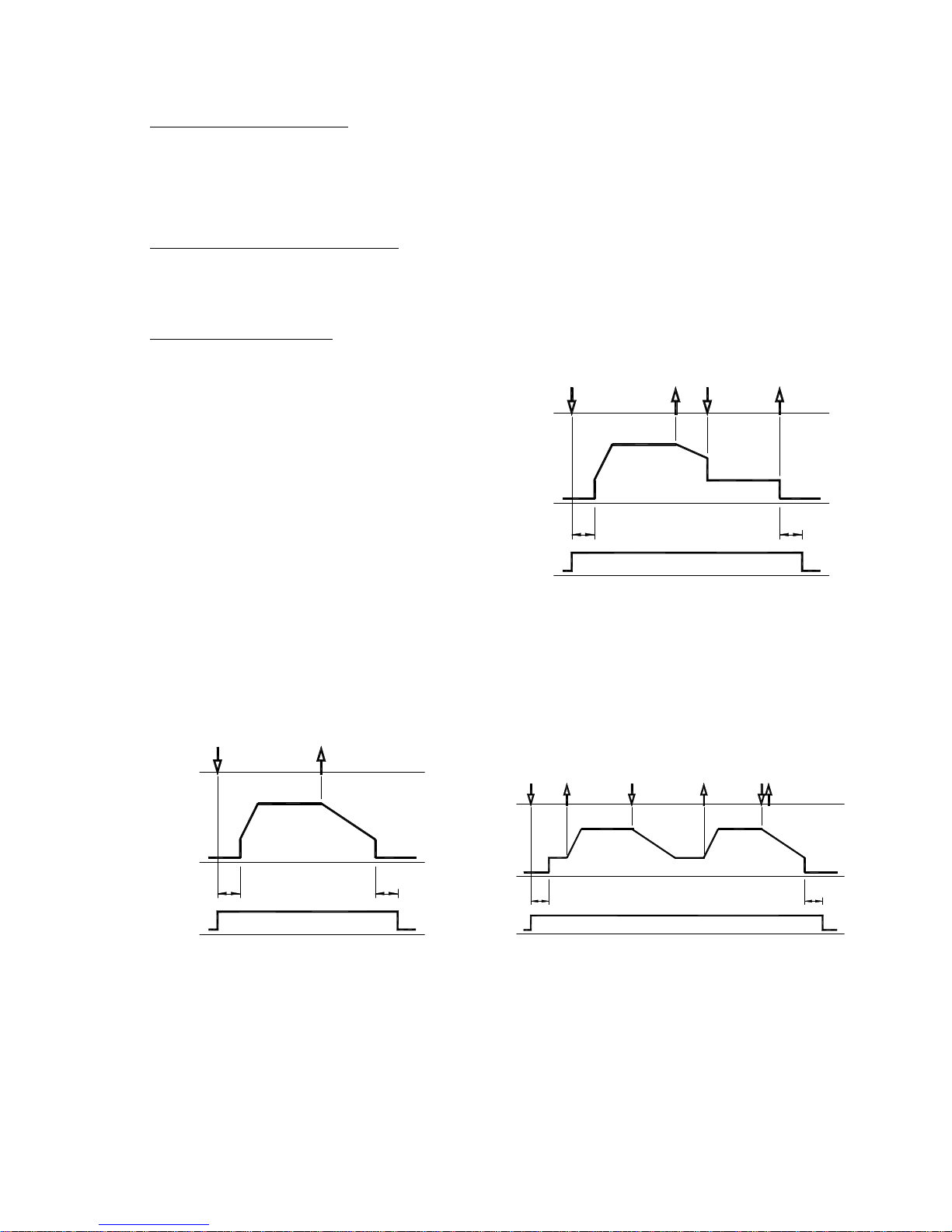
M. Trigger Mode Switch (V270-T only): This switch
changes between 2-step and 4-step trigger
sequences. For an explanation of these trigger
sequences refer to the trigger sequences explained
below.
N. Pulsing Mode Switch (V270-T only): In the TIG
welding modes, this switch turns the pulsing
function ON and controls the pulsing frequency
range (20Hz or 300Hz). In Stick welding mode, this
is not used.
The Pulsing LED next to the Pulsing Mode Switch
shows the pulsing frequency when pulsing is turned
ON. With this indication, the operator can adjust the
frequency to the desired value before welding.
(Note: At higher frequencies the LED flashes very
fast and seems to be continuously ON however it is
pulsing.)
O. Pulsing Frequency Control (V270-T only): When
the pulsing function is ON, this control knob will
adjust the pulsing frequency. The pulsing frequency
adjustment range is 0.2 - 20Hz or 3 - 300Hz
depending on the Pulsing Mode Switch position.
P. Pulsing On-time Control (V270-T only): When the
pulsing function is ON, this control knob will adjust
the pulsing on-time. The on-time can be adjusted
from 10% to 90% of the pulsing period.
Q. Pulsing Background Current Control (V270-T only):
When the pulsing function is ON, this control knob
will adjust the pulsing background current. This is
the current during the low portion of the pulse
waveform; it can be adjusted from 10% to 90% of

8
the welding current.
R. Downslope Control (V270-T only): In the TIG
welding modes, this control knob will adjust the
downslope time from 0.5 to 20 seconds. (The
upslope time is always 0.5 seconds.) Refer to the
trigger sequence section below to understand how
downslope is activated. In Stick welding mode, this
is not used.
S. Start/Crater Current Control (V270-T only): This
control knob will adjust the Start/Crater current from
10% to 90% of the welding current. For an
explanation of the start/crater operation, refer to the
trigger sequences explained below.
T. Postflow Control (V270-T only): In the TIG welding
modes, this control knob will adjust the shielding
gas postflow time from 0.5 to 30 seconds. (The
preflow time is always 0.5 seconds.) In Stick
welding mode, this is not used.
TIG Trigger Sequences
The V270-S, in Lift TIG mode with a remote control, will
operate in the 2-step mode. For the V270-T, TIG
welding can be done in either the 2-step or 4-step mode
which is selected by the Trigger Mode switch. The
specific sequences of operation for these two trigger
modes are explained below.
In these sequences, the Start/Crater current will be
used. For a V270-S, this current is 20% of the welding
current; for example, if the welding current is 100A the
Start/Crater current will be 20A. For the V270-T, the
Start/Crater current can be adjusted with the Start/Crater
current control knob.
2-Step TIG Sequence
With the Trigger Mode switch in the 2-step position, and
a TIG welding mode selected, the following welding
sequence will occur. To setup the machine for TIG
welding refer to the Output Connections section.
1. Press and hold the TIG torch trigger to start the
sequence. The machine will open the gas valve to
start the flow of the shielding gas. After a 0.5
second preflow time, to purge air from the torch
hose, the output of the machine is turned ON. At
this time the arc is started according to the selected
welding mode (Lift TIG or HF TIG). For more
information on the Lift or HF TIG starting methods,
refer to the Mode switch section above.
After the arc is started the output current will be
increased to the welding current. This increase, or
upslope, of the output current takes 0.5 seconds to
complete.
2. Release the TIG torch trigger to stop welding. The
machine will now decrease the output current at a
controlled rate, or downslope time, until the
Start/Crater current is reached and the output of the
machine is turned OFF. The downslope time is
adjusted by the Downslope Control knob.
After the arc is turned OFF, the gas valve will
remain open to continue the flow of the shielding
gas to the hot electrode and work piece. The
duration of this postflow shielding gas is adjusted by
the Postflow Control knob.
Possible variations of this standard sequence are shown
below. (If necessary, other variations are also available;
contact your Lincoln Electric sales representative for
more information.)
As shown above, it is possible to press and hold the TIG
torch trigger a second time during downslope to end the
downslope time and maintain the output current at the
Start/Crater current. When the TIG torch trigger is
released the output will turn OFF and the postflow time
will start.
4-Step Sequence
With the Trigger Mode switch in the 4-step position, and
a TIG welding mode selected, the following welding
sequence will occur. To setup the machine for TIG
welding refer to the Output Connections section.
1. Press and hold the TIG torch trigger to start the
sequence. The machine will open the gas valve to
start the flow of the shielding gas. After a 0.5
second preflow time, to purge air from the torch
hose, the output of the machine is turned ON. At
this time the arc is started according to the selected
welding mode (Lift TIG or HF TIG). For more
information on the Lift or HF TIG starting methods,
refer to the Mode switch section above.
After the arc is started the output current will be at
the Start/Crater current. This condition can be
maintained as long or as short as necessary.
OUTPUT
CURRENT
GAS
PRE-FLOW
BUTTON
TORCH
(1)
--- GAS ON ---
POST-FLOW
(2)
GAS
PRE-FLOW POST-FLOW
--- GAS ON ---
BUTTON
CURRENT
OUTPUT
TORCH
(1) (2)
CURRENT
GAS
PRE-FLOW
BUTTON
OUTPUT
TORCH
(1) (2)
--- GAS ON ---
POST-FLOW
(3) (4) (3A)

9
If the Start/Crater current is not necessary, do not
hold the TIG torch trigger as described at the
beginning of this step. Instead, quickly press and
release it. In this condition, the machine will
automatically pass from Step 1 to Step 2 when the
arc is started.
2. Release the TIG torch trigger to start the main part
of the weld. The output current will be increased to
the welding current. This increase, or upslope, of
the output current takes 0.5 seconds to complete.
3. Press and hold the TIG torch trigger when the main
part of the weld is complete. The machine will now
decrease the output current at a controlled rate, or
downslope time, until the Start/Crater current is
reached. The downslope time is adjusted by the
Downslope Control knob. This Start/Crater current
can be maintained as long or as short as necessary.
This sequence has an automatic restart so welding
will continue after this step. If the weld is completely
finished, use the following sequence instead of step
3 described above.
3A. Quickly press and release the TIG torch
trigger. The machine will now decrease the
output current at a controlled rate, or downslope
time, until the Start/Crater current is reached
and the output of the machine is turned OFF.
After the arc is turned OFF the postflow time
will start.
4. Release the TIG torch trigger. The output current
will again increase to the welding current, like in
step 2, to continue welding. When the main part of
the weld is complete go to step 3.
Possible variations of this standard sequence are shown
below. (If necessary, other variations are also available;
contact your Lincoln Electric sales representative for
more information.)
As shown here, after the
TIG torch trigger is quickly
pressed and released
from step 3A, it is
possible to press and hold
the TIG torch trigger
another time to end the
downslope time and
maintain the output
current at the Start/Crater
current. When the TIG
torch trigger is released
the output will again increase to the welding current, like
in step 4, to continue welding. When the main part of
the weld is complete go to step 3.
As shown here, again
after the TIG torch trigger
is quickly pressed and
released from step 3A, it
is possible to quickly
press and release the TIG
torch trigger a second
time to end the
downslope time and stop
welding.
OUTPUT
CURRENT
TORCH
BUTTON
GAS --- GAS ON ---
(3A) (4)
POST-FLOW
BUTTON
TORCH
CURRENT
OUTPUT
GAS --- GAS ON ---
(3A)

10
Electromagnetic Compatibility (EMC)
This machine has been designed in accordance with all relative directives and norms. However, it may still generate
electromagnetic disturbances that can affect other systems like telecommunications (telephone, radio, and television) or
other safety systems. These disturbances can cause safety problems in the affected systems. Read and understand
this section to eliminate or reduce the amount of electromagnetic disturbance generated by this machine.
This machine has been designed to operate in an industrial area. To operate in a domestic area it is
necessary to observe particular precautions to eliminate possible electromagnetic disturbances. The
operator must install and operate this equipment as described in this manual. If any electromagnetic
disturbances are detected the operator must put in place corrective actions to eliminate these disturbances
with, if necessary, assistance from Lincoln Electric.
Before installing the machine, the operator must check the work area for any devices that may malfunction because of
electromagnetic disturbances. Consider the following.
•Input and output cables, control cables, and telephone cables that are in or adjacent to the work area and the
machine.
•Radio and/or television transmitters and receivers. Computers or computer controlled equipment.
•Safety and control equipment for industrial processes. Equipment for calibration and measurement.
•Personal medical devices like pacemakers and hearing aids.
•Check the electromagnetic immunity for equipment operating in or near the work area. The operator must be sure
that all equipment in the area is compatible. This may require additional protection measures.
•The dimensions of the work area to consider will depend on the construction of the area and other activities that are
taking place.
Consider the following guidelines to reduce electromagnetic emissions from the machine.
•Connect the machine to the input supply according to this manual. If disturbances occur if may be necessary to take
additional precautions such as filtering the input supply.
•The output cables should be kept as short as possible and should be positioned together. If possible connect the
work piece to ground in order to reduce the electromagnetic emissions. The operator must check that connecting
the work piece to ground does not cause problems or unsafe operating conditions for personnel and equipment.
•Shielding of cables in the work area can reduce electromagnetic emissions. This may be necessary for special
applications.
INVERTEC V270 Technical Specifications
INPUT
Input Voltage
400V ±15%
Three Phase
Input Power at Rated Output
6.5kW @ 100% Duty Cycle
9.9kW @ 35% Duty Cycle
Frequency
50/60 Hertz (Hz)
RATED OUTPUT AT 40°C
Duty Cycle
(Based on a 10 min. period)
100%
35%
Output Current
200A
270A
Output Voltage
28.0 Vdc
30.8 Vdc
OUTPUT RANGE
Welding Current Range
5-270 Amps Maximum Open Circuit Voltage
48 Vdc
RECOMMENDED INPUT CABLE AND FUSE SIZES
Fuse or Circuit Breaker Size
20A Superlag Input Power Cable
4 Conductor, 2.5mm2
PHYSICAL DIMENSIONS
Height
385 mm Width
215 mm Length
480 mm Weight
13.5 – 14.5 Kg
Operating Temperature
–20°C to +40°C Storage Temperature
-25°C to +55°C
For any maintenance or repair operations it is recommended to contact the nearest technical service center or Lincoln
Electric. Maintenance or repairs performed by unauthorized service centers or personnel will null and void the
manufacturers warranty.

18
Spare Parts, Parti di Ricambio, Ersatzteile, Lista de Piezas de
Recambio, Pièces de Rechange, Deleliste, Reserve
Onderdelen, Reservdelar
Spare Parts
(* = Item not shown in diagram)
Item Part Number Description QTY
1W95X0331R FRONT PANEL 1
2W95X0332R REAR PANEL 1
3W93X0327R COMPLETE EXTERNAL BASE 1
4W93X0326R WRAPAROUND 1
5W93X0312R INTERNAL UPPER SUPPORT 1
6W93X0308R INTERNAL BASE 1
7A W93X0300R CONTROL PANEL (V270-S) 1
7B W93X0296R CONTROL PANEL (V270-T) 1
8W59X0310R HF TRANSFORMER (only V270-T) 1
9W7200003R FAN 1
10 * W8400006R INPUT CABLE CLAMP 1
11 W7511703R INPUT SWITCH 1
12 W7690350R DINSE CONNECTOR 2
13 W05X0290R INPUT P.C. BOARD 1
14 W05X0298R INVERTER P.C. BOARD 2
15 W05X0285R HF P.C. BOARD (only V270-T) 1
16A W05X0317R DISPLAY P.C. BOARD (V270-S) 1
16B W05X0286R DISPLAY P.C. BOARD (V270-T) 1

19
17 W05X0302R CONTROL INTERFACE P.C. BOARD 1
18 W05X0233R CONTROL P.C. BOARD 1
19 W05X0322R REMOTE P.C. BOARD WITH REMOTE CONNECTOR 1
20 W6100315R TRIGGER CONNECTOR (only V270-T) 1
21 W8700022R KNOB (LARGE) 1
22 W8700016R KNOB (SMALL) 2 - 6
23 W8800071R FEMALE QUICK CONNECT GAS CONNECTOR (only V270-T) 1
24 * W78X0337R INPUT CORD 1
25 W92X0228-2R HANDLE 1
26 * W92X0264R CARRYING STRAP 1
27 W8500004R GAS SOLENOID (only V270-T) 1
Parti di ricambio
(* = parte non mostrata nel disegno)
Rif N. parte Descrizione QTY
1W95X0331R PANNELLO FRONTALE 1
2W95X0332R PANNELLO POSTERIORE 1
3W93X0327R BASE ESTERNA COMPLETA 1
4W93X0326R MANTELLO 1
5W93X0312R SUPPORTO INTERNO SUPERIORE 1
6W93X0308R BASE INTERNA 1
7A W93X0300R PANNELLO COMANDI (V270-S) 1
7B W93X0296R PANNELLO COMANDI (V270-T) 1
8W59X0310R TRASFORMATORE HF (solo V270-T) 1
9W7200003R VENTOLA 1
10 * W8400006R PRESSACAVO PER CAVO ALIMENTAZIONE 1
11 W7511703R INTERRUTTORE ALIMENTAZIONE 1
12 W7690350R DINSE 2
13 W05X0290R SCHEDA INGRESSO 1
14 W05X0298R SCHEDA INVERTER 2
15 W05X0285R SCHEDA HF (solo V270-T) 1
16A W05X0317R SCHEDA DISPLAY (V270-S) 1
16B W05X0286R SCHEDA DISPLAY (V270-T) 1
17 W05X0302R SCHEDA INTERFACCIA CONTROLLO 1
18 W05X0233R SCHEDA CONTROLLO SALDATURA 1
19 W05X0322R SCHEDA COMANDO A DISTANZA COMPLETA DI CONNETTORE 1
20 W6100315R CONNETTORE PULSANTE (solo V270-T) 1
21 W8700022R MANOPOLA COMPLETA (GRANDE) 1
22 W8700016R MANOPOLA COMPLETA (PICCOLA) 2 - 6
23 W8800071R GIUNTO AD INNESTO RAPIDO PER GAS, femmina (solo V270-T) 1
24 * W78X0337R CAVO ALIMENTAZIONE 1
25 W92X0228-2R MANIGLIA 1
26 * W92X0264R CINGHIA CON SPALLACCIO 1
27 W8500004R ELETTROVALVOLA (solo V270-T) 1

20
Accessories, Accessori, Zubehör, Accesorios, Accessoires,
Tilleggsutstyr, Accessores, Tillbehör
W6100316R Trigger Connector (For V270-T)
Connettore per pulsante torcia (Per modello V270-T)
W6100317R Remote Connector [text removed]
Connettore per comando a distanza
W8800072R Male Quick Connect Gas Fitting (For V270-T)
Giunto ad innesto rapido per gas, maschio (Per modello V270-T)
K10095-1-10 Hand Amptrol [text removed]
Hand Amptrol
K870 Foot Amptrol [text removed]
Foot Amptrol
Table of contents